Introduction to Manufacturing Operations Management (MOM)
Manufacturing operations management sits at the intersection of business planning and shopfloor reality. It represents the coordinated management of production operations between enterprise planning systems and physical process control. Where ERP handles long-term scheduling and resource allocation, and automation systems handle real-time machine control, manufacturing operations management occupies the middle ground: translating business intent into executable work and feeding actual results back up the chain.
This article focuses specifically on the standards that define and measure manufacturing operations management. The goal is not to recommend software products or propose architectures. Instead, the aim is to walk through the major models and how they relate to one another.
The term MOM gained traction in the 2000s as ISA-95 and manufacturing execution systems concepts evolved toward a broader operational scope. Before that, manufacturers often referred to MES, SCADA, or various shop floor control systems without a unifying framework. Standards such as ISA-95, IEC/ISO 62264, and ISO 22400 now offer a shared language for MOM functions, data exchanges, and performance indicators. Understanding these standards helps operations teams, engineers, and leadership speak the same language when discussing how production should be managed.
What Is MOM? Definitions, Scope, and Boundaries
At a high level, manufacturing operations management is the set of activities that manage, monitor, track, and improve manufacturing operations in real time or near-real time. It bridges the gap between what the business wants to produce and what actually happens on the production floor.
MOM covers several operational domains that together form the entire manufacturing process:
- Production operations: scheduling, dispatching, and tracking work orders through the production process
- Quality operations: enforcing quality standards, inspections, and defect logging
- Maintenance operations: coordinating equipment upkeep, repairs, and reliability tracking
- Inventory operations: managing raw materials, work-in-progress, and finished goods on the floor
These domains align with terminology from ISA-95 and IEC 62264, which refer to them as Production Operations Management, Maintenance Operations Management, Quality Operations Management, and Inventory Operations Management.
The functional boundary between manufacturing operations management and adjacent systems is drawn along three zones:
Zone
Function
Examples
Planning
Long-term and aggregate decisions about what to make, when, and with what resources
MRP, rough-cut capacity planning, demand forecasting in ERP
Operations Management
Detailed scheduling, dispatching, resource allocation, and real-time coordination
Work order management, production scheduling, workforce management
Control
Real-time actuation, feedback loops, and machine-level automation
PLCs, SCADA, DCS, sensor networks
Standards frame MOM at “Level 3” in the classic automation hierarchy. This places it above real-time control (Level 2) and below business planning (Level 4). The Level 3 boundary is where production efficiency meets business processes. Planning largely happens at Level 4, execution and coordination at Level 3, and closed-loop control at Levels 2 through 0.
Definitions vary slightly between ISA, ISO, and MESA documents, but all center on the same idea: orchestrating the execution of production in alignment with business plans while collecting performance data to support continuous improvement.
Why Multiple MOM-Related Standards Exist
Different standards bodies developed MOM-related specifications to address complementary needs. ISA focused on functional models and integration. IEC and ISO addressed international harmonization and performance measurement. MESA and the World Batch Forum (WBF) historically contributed best practices and batch-specific guidance.
The timeline helps explain the landscape:
- ISA-95 Part 1 was first published in 1995, with subsequent parts released through the early 2000s
- ISA-95 was later adopted as IEC 62264 and subsequently as ISO 62264, creating alignment across international standards bodies
- ISO 22400, focusing on KPIs for manufacturing operations, was published between 2014 and 2017
Regional and sector-specific regulations also influenced the proliferation of MOM-adjacent guidance. FDA regulations in life sciences demand traceability and validation. EN standards in Europe address safety and environmental regulations. AS9100 in aerospace requires documented quality management systems and process control.
The overlapping scopes are intentional. The primary mom standards describe different aspects of the same operational reality:
Standard
Primary Focus
ISA-95 / IEC 62264
What functions exist and how information flows between levels
ISO 22400
How to measure and quantify MOM performance
ISA-88
How batch processes should be structured and controlled
Sector standards (AS9100, IATF 16949)
Industry-specific quality and compliance requirements
Convergence efforts exist. The adoption of ISA-95 as IEC/ISO 62264 represents one major unification. However, complete standardization has not been achieved because different use cases and stakeholder communities have distinct priorities. A discrete electronics manufacturer has different needs than a batch pharmaceutical producer. A global supply chain network has different integration challenges than a single-site operation.
The goal of multiple standards is interoperability and comparability, not vendor lock-in. When organizations reference these standards, they can describe their manufacturing operations using internationally recognized terminology that suppliers, auditors, and partners understand.
The Role of ISA-95 and IEC/ISO 62264 in MOM
ISA-95 is the foundational family of standards for describing manufacturing operations management functions and information flows. Developed by the International Society of Automation, its parts were later adopted as IEC 62264 and then ISO 62264. This makes ISA-95 the backbone for discussing what MOM does and how it connects to the rest of the enterprise.
The main conceptual contributions of ISA-95 and IEC 62264 include:
- A functional hierarchy spanning Levels 0 through 4
- Models for production, quality, maintenance, and inventory management
- Object models defining the data entities exchanged between enterprise and control levels
- Activity models describing how manufacturing operations are managed
ISA-95 defines the Level 3 space where a manufacturing operations management system lives. This distinguishes it from enterprise resource planning at Level 4 and automation and control at Levels 0 through 2.
The key elements of the standard are organized across multiple parts:
- Part 1: Models and terminology for enterprise-control integration
- Part 2: Object models and attributes for information exchange
- Part 3: Activity models of manufacturing operations management
- Parts 4 and beyond: Object models for integration, batch specifics, and extended scenarios
MOM in ISA-95 is decomposed into four major domains that cover actual manufacturing operations activities:
- Production Operations Management: managing work orders, production scheduling, dispatching, and tracking
- Maintenance Operations Management: coordinating equipment maintenance and reliability
- Quality Operations Management: enforcing quality control, inspections, and nonconformance handling
- Inventory Operations Management: tracking materials through the shopfloor
These domains work together to ensure that manufacturing processes execute according to plan while adapting to real-time conditions.
ISA-95 Levels and the MOM Boundary
The classic ISA-95 levels provide a conceptual stack from business planning down to physical processes:
Level 4: Business Planning and Logistics This is where ERP, supply chain management, and long-term planning reside. Decisions at this level involve what products to make, in what quantities, and when. Demand forecasting, master scheduling, and financial planning happen here. The time horizon spans days, weeks, or months.
Level 3: Manufacturing Operations Management This is the MOM layer. Detailed scheduling, dispatching, resource allocation, and real-time tracking occur here. The manufacturing operations management system translates Level 4 plans into actionable work instructions and coordinates production efficiency on the floor. Time horizons range from seconds to shifts to days.
Level 2: Supervisory Control SCADA systems, HMIs, and supervisory logic operate at this level. They provide operators with visibility into process status and enable manual overrides when needed.
Level 1: Direct Control PLCs, controllers, and feedback loops manage individual pieces of equipment. They execute setpoints and maintain process parameters.
Level 0: Physical Process This is the actual production process: machines running, materials flowing, parts being assembled or transformed.
The boundaries help define responsibilities and data exchanges. Planning decisions flow down from Level 4 to Level 3. Execution instructions flow from Level 3 to Levels 2 through 0. Status, measurements, and production performance flow back up the stack.
In practice, data can cross levels in near real time. Modern systems architectures apply various integration patterns to enable this. But the logical separation in ISA-95 helps standardize what each layer is responsible for and what information it should provide.
ISO 22400: KPIs and Metrics for MOM
ISO 22400 is a series of standards that define key performance indicators and terminology for manufacturing operations management. While ISA-95 describes what functions exist, ISO 22400 describes how to measure them.
ISO 22400 provides:
- Definitions of MOM-related terms such as availability, performance, and quality rate
- Formulas for KPIs, including Overall Equipment Effectiveness (OEE)
- Guidance on interpreting KPIs for different production contexts
The standard helps organizations achieve standardized processes for performance measurement. When two plants calculate OEE using ISO 22400 definitions, the results are comparable. This matters for operations leaders managing multi-site operations or tracking improvements over time.
ISO 22400-2 focuses specifically on KPIs for manufacturing operations and references concepts from ISA-95 and IEC 62264. This alignment ensures that metrics correspond to the operations models defined in those standards.
Key categories of KPIs in ISO 22400 include:
Category
Example KPIs
Throughput and time
Cycle time, throughput rate, production time
Quality
First-pass yield, defect rate, scrap ratio
Equipment
OEE, availability, performance rate
Maintenance
MTBF (mean time between failures), MTTR (mean time to repair)
Inventory
Stock turns, inventory accuracy
The position of ISO 22400 in the standards landscape is clear: ISA-95 describes what MOM functions and information objects exist; ISO 22400 describes how to quantify MOM performance. Together, they enable organizations to define operations and measure results using internationally recognized methods.
Relating ISO 22400 KPIs to ISA-95 MOM Functions
The relationship between ISO 22400 KPIs and ISA-95 operations domains is direct. Each domain generates data that feeds specific metrics:
Production Operations Management
- OEE captures availability, performance, and quality in a single metric
- Throughput and cycle time measure production process speed
- Production scheduling adherence tracks plan versus actual
Maintenance Operations Management
- MTBF indicates equipment reliability
- MTTR measures how quickly issues are resolved
- Planned versus unplanned maintenance ratios show maintenance management maturity
Quality Operations Management
- First-pass yield measures how often products pass inspection without rework
- Defect density tracks quality issues per unit or batch
- These metrics support quality improvement initiatives and audit readiness
Inventory Operations Management
- Stock turns indicate how efficiently inventory moves through the system
- Inventory accuracy measures alignment between records and physical counts
- These metrics help reduce waste and avoid excess inventory
Conceptually, ISA-95 defines the activities generating data, while ISO 22400 defines how to transform that data into comparable indicators. Using both standards together allows organizations to describe both process structure and performance measurement using consistent terminology.
This combination supports real time data collection and analysis for operational excellence. When mom systems collect data aligned with ISA-95 models and calculate KPIs per ISO 22400 definitions, the resulting manufacturing intelligence is consistent and actionable.
Other Standards and Reference Models Touching MOM
Several additional standards intersect with the MOM layer without being MOM definitions themselves. These shape how MOM processes must behave to ensure quality, safety, and compliance.
ISA-88 (Batch Control) ISA-88 provides models for batch process structuring. It defines procedures, units, equipment modules, and recipes. In batch industries such as pharmaceuticals, food and beverage, and specialty chemicals, ISA-88 models integrate with ISA-95 production operations management. The recipe and procedure structures from ISA-88 feed into MOM scheduling and execution.
ISO 9001 (Quality Management Systems) ISO 9001 establishes requirements for quality management systems. It influences how MOM quality processes are designed, documented, and audited. Traceability, process control, and continuous improvement requirements in ISO 9001 translate into MOM activities.
Sector-Specific Standards Relevant international mom standards from specific industries add compliance requirements:
- IATF 16949 for the automotive sector mandates process control and traceability
- AS9100 in aerospace requires documented standard operating procedures and audit trails
- FDA 21 CFR Part 11 in life sciences demands electronic record integrity
OPC UA Companion Specifications Broader industrial interoperability efforts reference ISA-95 models. OPC UA companion specifications provide standardized data models that align with ISA-95 object models. This enables mom software and control systems to exchange data using consistent structures.
These standards are not MOM definitions per se, but they shape what MOM must accomplish. When regulatory requirements demand traceability, risk management, or documentation, MOM processes must deliver. When customer expectations require high quality products and on-time delivery, MOM must coordinate production to meet those goals.
Boundaries Between Planning, MOM, and Control in Practice
Standards collectively draw lines between three zones of manufacturing management. Understanding these boundaries helps teams align their systems and processes without overlap or ambiguity.
Planning (Level 4) Planning involves longer-term, aggregate decisions. What products should be made? In what quantities? When? What resources are available across the entire supply chain? Chain management and demand forecasting happen here. Planning decisions flow down to MOM as production orders, schedules, and master data.
Manufacturing Operations Management (Level 3) MOM handles short-term, detailed coordination. It takes planning inputs and translates them into specific work orders, production scheduling, dispatching, and resource allocation. MOM coordinates workforce management, tracks production efficiency, and manages quality control activities. Results flow back up to planning as production performance, consumption data, and quality reports.
Control (Levels 0-2) Control manages real-time actuation and feedback. PLCs execute setpoints. Sensors report status. Control loops maintain process parameters. MOM sends detailed work instructions and setpoints down to control. Control sends status and measurements back up to MOM.
Using terminology from ISA-95, typical data exchanges include:
Direction
Data Types
Level 4 → Level 3
Demand, master data, production schedules, resource plans
Level 3 → Level 4
Production performance, consumption, quality results, inventory status
Level 3 → Level 2-0
Work instructions, setpoints, recipes, dispatch orders
Level 2-0 → Level 3
Equipment status, measurements, process data, completion signals
Standards generally avoid mandating specific systems architectures. Instead, they define business processes, interfaces, and information models that can be realized in many ways. This allows organizations to choose the right mom solution for their context while maintaining compatibility with partners and supply chain stakeholders.
Respecting these conceptual boundaries helps organizations avoid overlap when adopting multiple standards. ISA-95 defines structure. ISO 22400 defines measurement. Sector standards define compliance requirements. Together, they form a coherent picture of how manufacturing operations management connects to the rest of the manufacturing stack.
When flexible manufacturing operations management aligns with these standards, organizations gain operational efficiency, reduce waste, and achieve effective collaboration across sites and suppliers.

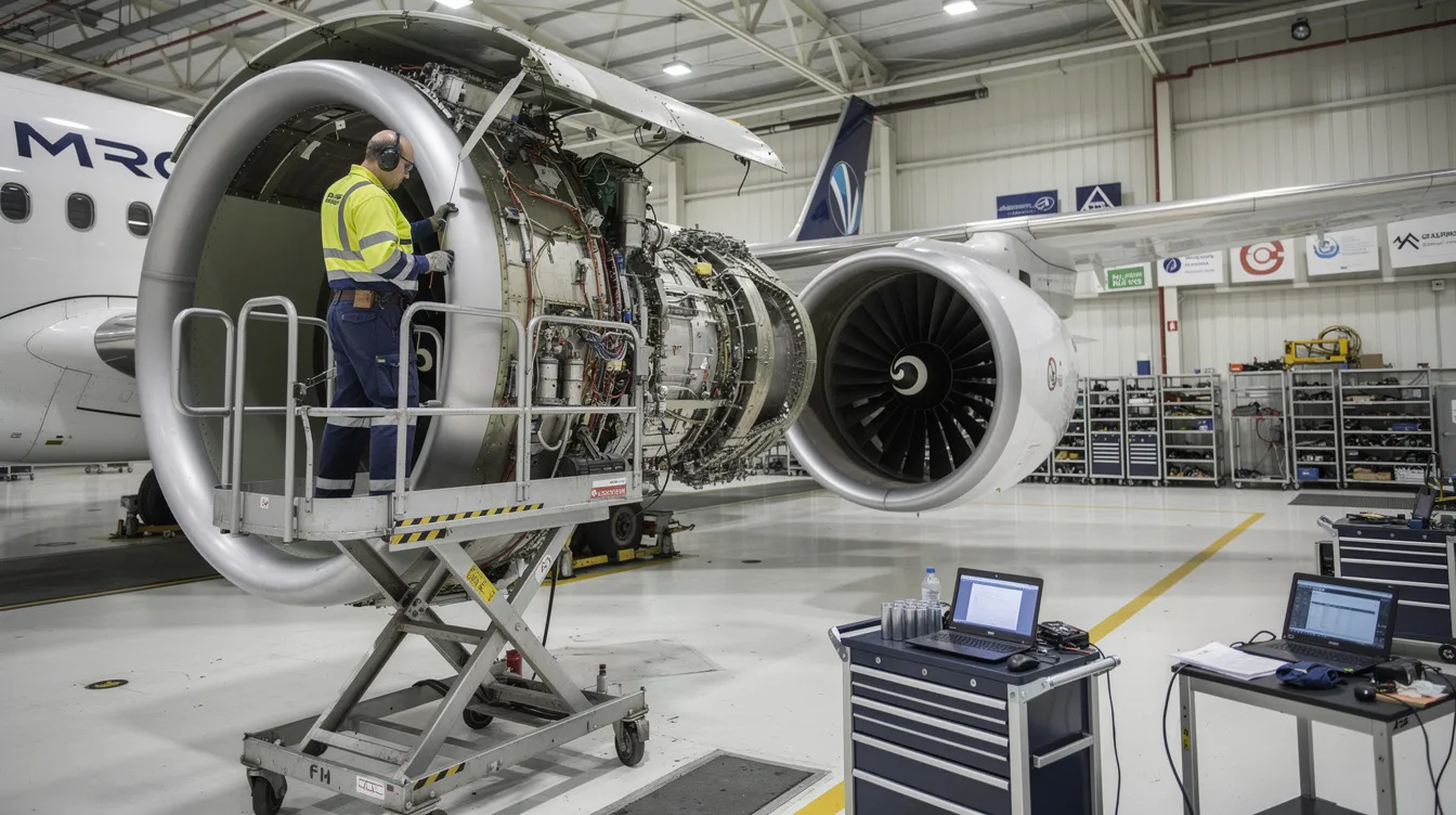
How Aerospace and MRO Operations Use MOM Standards (Contextual View)
Highly regulated sectors such as aerospace manufacturing and maintenance, repair, and overhaul (MRO) rely on MOM-aligned practices to meet stringent compliance requirements. AS9100, FAA, EASA, NADCAP, and ITAR regulations demand documented processes, traceability, and audit-ready operations.
In these environments, the primary mom standards applied to core operational challenges include:
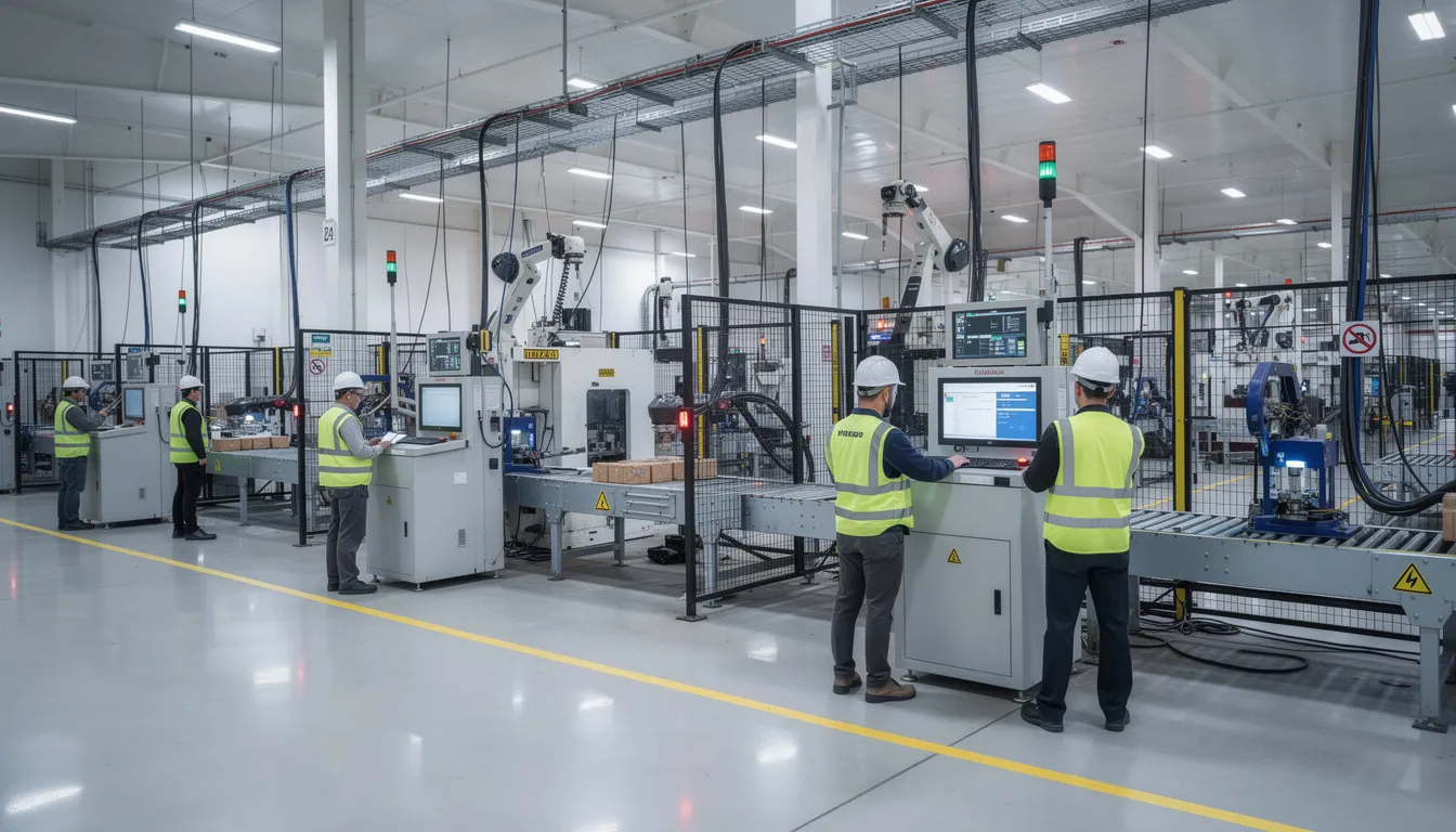
Production Operations Management Configuration control and build sequence integrity are critical. Work orders must track exactly which parts, at which serial numbers, were installed in which assemblies. Lean manufacturing principles combined with standardized MOM processes help maintain overall operational efficiency while meeting compliance requirements.
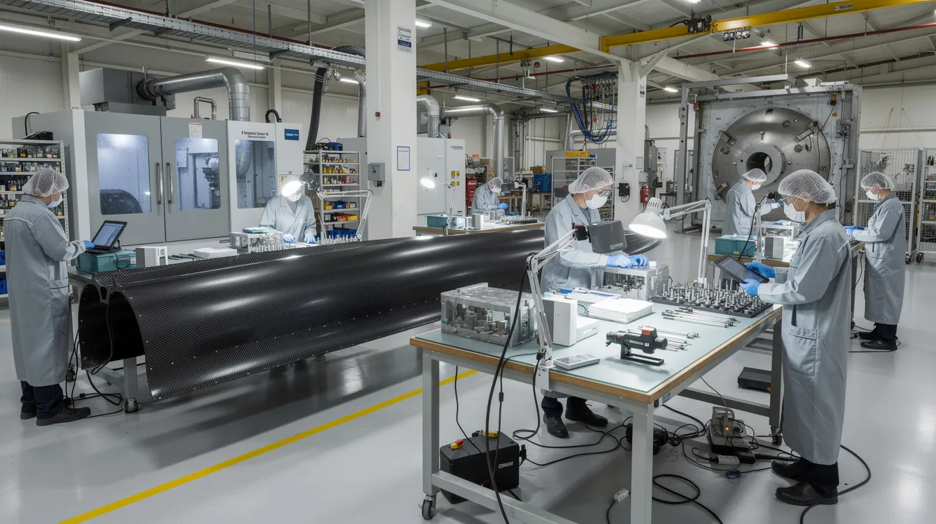
Quality Operations Management First article inspection, in-process checks, and final acceptance all generate quality records. These feed into quality management and support audit trails required by AS9100 and FAA oversight. Advanced analytics on quality data can identify trends and support quality improvement before issues escalate.
Inventory Operations Management Serialized part traceability spans the global supply chain network. Organizations must track raw materials from receiving through consumption. Multi-tier supplier coordination requires shared visibility into inventory status and material certifications.
Maintenance Operations Management In MRO operations, maintenance management includes tracking component histories, managing repair cycles, and documenting compliance with airworthiness directives. MTBF and MTTR metrics from ISO 22400 apply directly to fleet reliability analysis.
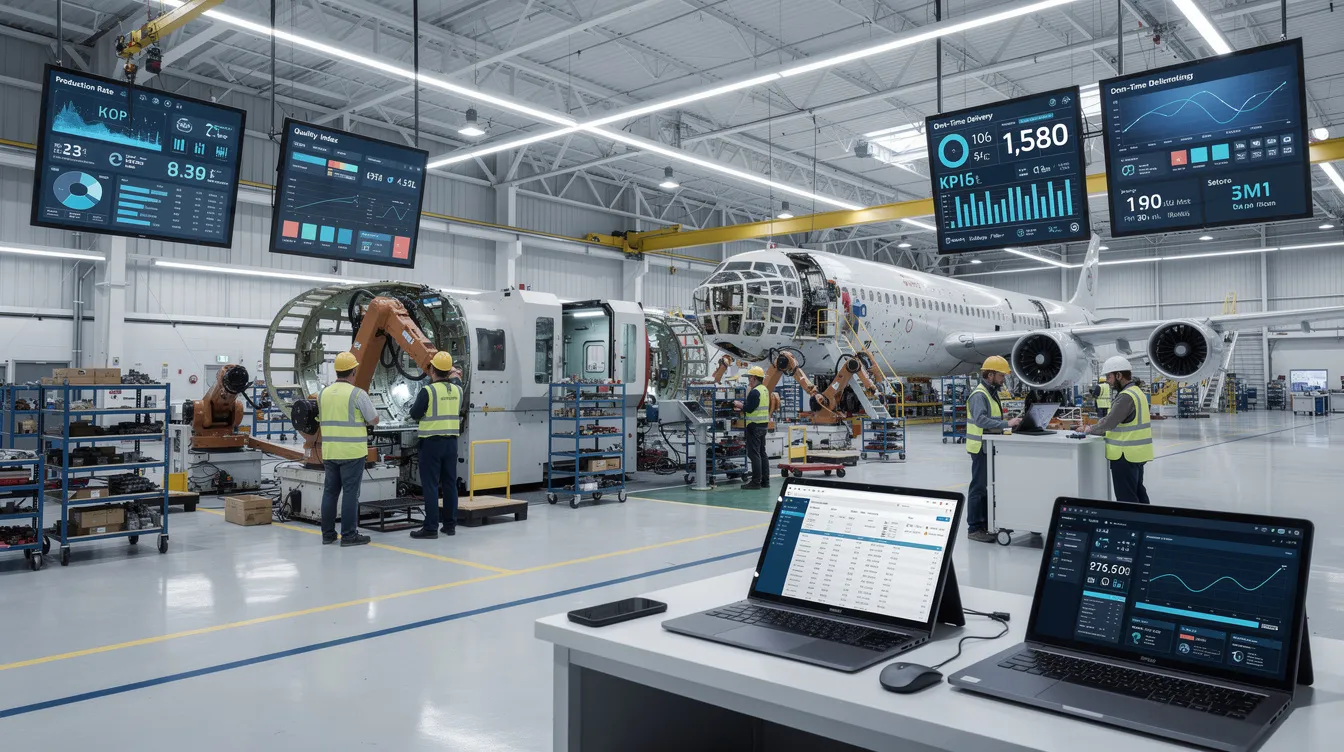
Organizations in aerospace and MRO often implement ISA-95/IEC 62264 models alongside ISO 22400 KPIs. This combination supports data analytics for improved safety and resource efficiency. Digital transformation in these sectors means aligning digital operations platforms with MOM standards to ease integration and reporting.
Current industry discussions in aerospace increasingly focus on how mom systems can support smart manufacturing initiatives while maintaining compliance. The challenges identified include integrating existing systems, managing incremental improvements without disrupting production, and ensuring that digital workflows achieve competitive advantage through better data rather than just automation.
When digital operations platforms align their data structures and workflows with MOM standards, organizations can more easily connect ERP, MES, supplier portals, and quality systems. This alignment supports cost reduction through reduced rework, waste reduction through better visibility, and customer satisfaction through reliable delivery.
The standards provide a shared vocabulary. Implementation provides the value. Understanding where manufacturing operations management sits in the hierarchy helps aerospace operations teams align production planning, execution, and measurement while meeting the regulatory requirements that define their industry.
For aerospace manufacturers and MRO organizations navigating these standards, the path forward involves understanding how MOM concepts apply to your specific operations, compliance requirements, and supply chain complexity. The standards exist to enable consistency and interoperability. The work lies in translating those frameworks into practical workflows that deliver operational excellence on the shopfloor.