Category: MES, ERP, PLM and Data Integration

System boundary clarity and governed integration patterns across ERP, MES, PLM, QMS, and suppliers. Focuses on interoperability that preserves traceability, audit trails, and operational trust.

  • IEC 62264 Manufacturing Operations: Standards-Aligned Overview

    IEC 62264 Manufacturing Operations: Standards-Aligned Overview

    Manufacturing enterprises operating across multiple sites, suppliers, and jurisdictions face a persistent challenge: how to describe what happens between business planning and the physical processes on the factory floor. The answer, for many global organizations, lies in IEC 62264.

    This international standard series provides a common framework for enterprise control system integration, giving manufacturers a shared vocabulary for how enterprise systems and control systems exchange information. For aerospace organizations coordinating production, maintenance, and quality operations across complex supply chains, IEC 62264 offers a neutral reference that supports consistent communication regardless of geography or technology platform.

    This blog post examines the scope and purpose of IEC 62264, its relationship to ISA 95, and its role in global manufacturing operations.

    What Is IEC 62264 in Manufacturing Operations?

    IEC 62264 is the internationally adopted version of the ISA-95 enterprise and control system integration standard, focused specifically on manufacturing operations management at Level 3 in the hierarchical model. Published by the International Electrotechnical Commission, IEC 62264 provides a common reference model for how business planning and logistics systems (Level 4) interact with manufacturing operations and control functions (Levels 3 and 2).

    The standard exists to serve as a globally recognized counterpart to the ISA-95 series originally developed by the International Society of Automation. While ISA-95 carries ANSI/ISA designation, IEC 62264 enables organizations worldwide to reference the same technical content through their national or regional standards frameworks.

    IEC 62264 is widely applied in discrete, batch, and continuous manufacturing sectors. It holds particular relevance for aerospace and MRO operations that rely on interconnected systems including enterprise resource planning, manufacturing execution systems, product lifecycle management, and quality management systems. These environments require precise coordination of production orders, maintenance records, traceability data, and compliance documentation across multiple facilities and suppliers.

    Connect981 is a platform built for aerospace manufacturing and MRO teams that aligns to IEC 62264 and ISA-95 concepts. Its approach to organizing digital work instructions, traceability, and supplier workflows reflects the levels, information flows, and terminology established by these standards.

    Scope and Purpose of IEC 62264

    IEC 62264 defines models, terminology, and interfaces that describe how enterprise systems and manufacturing operations exchange information. It does not prescribe specific technologies or software products. Instead, it provides a conceptual framework that allows different stakeholders, vendors, and sites to interpret and design systems consistently.

    The core scope centers on control system integration, specifically the interactions between:

    Level

    Domain

    Examples

    Level 4

    Business planning and logistics

    ERP, supply chain planning, order management

    Level 3

    Manufacturing operations management

    MES, MOM, production scheduling, quality management

    Level 2

    Supervisory control

    SCADA, DCS, supervisory systems

    Level 1

    Sensing and manipulating

    Sensors, actuators, devices

    Level 0

    Physical processes

    Actual production equipment and physical assets

    The purpose of IEC 62264 is to standardize how manufacturing activities, information objects, and information flows are described. This standardization allows organizations to map their existing systems into a common reference architecture without requiring a complete technology overhaul.

    For aerospace and MRO organizations, this scope supports consistent handling of:

    • Production orders and work schedules
    • Maintenance orders and equipment states
    • Quality data and inspection records
    • Materials, lot tracking, and serialization
    • Resource allocation across plants and suppliers

    The standard’s purpose is informational and modeling-oriented. It defines activity models and object models. It does not mandate how those models should be implemented in any specific technology or business processes.

    Relationship Between IEC 62264 and ISA-95

    IEC 62264 and ISA 95 cover the same conceptual territory. They were developed in close coordination, with IEC 62264 effectively mirroring the content of ISA-95 for international use.

    ISA-95 was first developed and published by ISA in the mid-1990s and early 2000s. The standard addressed a critical functional gap: the interface between enterprise functions operating at Level 4 and process control functions operating at Level 2. When this content achieved sufficient technical maturity, it was adopted and published by the IEC as the IEC 62264 series to provide a global electrotechnical standard.

    The part structure aligns closely between the two series:

    ISA-95 Part

    IEC 62264 Part

    Focus Area

    ISA-95 Part 1

    IEC 62264-1

    Models and terminology, Level 3-4 interface

    ISA-95 Part 2

    IEC 62264-2

    Object model attributes

    ISA-95 Part 3

    IEC 62264-3

    Activity models of MOM

    ISA-95 Part 4

    IEC 62264-4

    Object models and attributes

    ISA-95 Part 5

    IEC 62264-5

    Business-to-manufacturing transactions

    Conceptually, both series share the same hierarchical model defined for organizing manufacturing levels, the same object models for entities like materials and equipment, and the same activity models for production, maintenance, quality, and inventory operations. Document layouts and editorial details may differ between ISA and IEC publications, but the technical substance remains equivalent.

    Connect981’s information model and workflows are designed to be understandable in both ISA-95 and IEC 62264 terms. This helps aerospace teams collaborate across global partners who may refer to either naming convention.

    Why IEC Versions Exist Alongside ISA Standards

    ISA is a professional society. IEC is a formal international standards body recognized by many national standards organizations and regulators. This distinction explains why both designations exist for the same technical content.

    IEC 62264 exists to provide the ISA-95 concepts in a format that can be adopted as national or regional electrotechnical standards. In Europe, for example, CENELEC can adopt IEC standards directly. Other national committees worldwide follow similar processes. When organizations reference IEC 62264, they reference a standard with formal international standing.

    Several practical factors drive this dual publication approach:

    • Procurement and contracts: Many countries and procurement frameworks reference IEC standards explicitly. Having IEC 62264 makes it easier for multinational manufacturers to align on a single international reference.
    • Regulatory alignment: Different jurisdictions have different standards bodies. IEC publication provides equal weight across multiple regulatory environments.
    • Community coordination: The coexistence of ISA-95 and IEC 62264 allows both automation professionals and national standards bodies to work from a harmonized conceptual base while following their own publication processes.

    This dual publication is especially important in global industries such as aerospace. OEMs, Tier-1 suppliers, and MRO providers must coordinate standards language across multiple jurisdictions. A supplier in Germany can reference IEC 62264 knowing that a customer in the United States recognizes the same technical content under the ISA-95 designation.

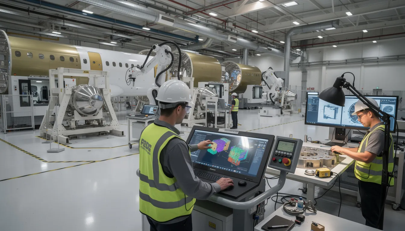
    The image depicts an industrial aerospace manufacturing floor bustling with workers collaborating alongside automated equipment, showcasing the integration of enterprise control systems and manufacturing operations. This environment highlights the synergy between technology and business processes, emphasizing the efficient management of manufacturing activities within the aerospace sector.

    How IEC 62264 Mirrors ISA-95 Conceptually

    The technical content of IEC 62264 is designed to be conceptually equivalent to ISA-95. Models, definitions, and terminology align across both series by design.

    Both standards use a hierarchical view of manufacturing based on the Purdue Reference Model. This layers defined structure organizes technology and business processes from physical production (Level 0) up through business planning (Level 4). The hierarchy provides a common reference for discussing where different systems and functions operate.

    In both ISA-95 and IEC 62264, Level 3 (Manufacturing Operations Management) breaks into four key activity areas:

    Activity Area

    Scope

    Production operations

    All the activities related to converting materials into products

    Maintenance operations

    Activities taking place to maintain equipment availability

    Quality operations

    Activities related to measuring and verifying product and process quality

    Inventory operations

    Activities for managing materials and storage

    Both series define similar object models for entities such as:

    • Material (material lots, sublots, serial numbers)
    • Equipment (work centers, production units, storage zones)
    • Personnel (qualifications, assignments)
    • Process segments (routing steps, operations)

    These object models enable consistent descriptions of what is being planned, executed, and recorded across manufacturing operations domain applications.

    Connect981 uses these same conceptual objects and levels. Work orders, routing, resources, and quality records map cleanly to IEC 62264 and ISA-95 aligned architectures. This alignment makes it easier to integrate enterprise system data with shopfloor execution.

    IEC 62264 Part Structure for Manufacturing Operations

    IEC 62264 is organized into multiple parts, each addressing a specific aspect of enterprise and control integration. Understanding this structure helps organizations locate the relevant models and terminology for their needs.

    IEC 62264-1: This part establishes the foundational framework, including the five-level hierarchy, the manufacturing operations management domain definition (Level 3), and the interfaces between Level 3 and Level 4. The latest edition includes extended functional and equipment hierarchies, a physical asset equipment model, and generic models of manufacturing operations management categories. The interface content describes what information flows between manufacturing operations and other enterprise functions.

    IEC 62264-2: Focuses on object model attributes for information exchanges between enterprise and control domain systems.

    IEC 62264-3:2016: The second edition defines activity models of manufacturing operations management. It covers production operations management, maintenance operations management, quality operations management, and inventory operations management. The 2016 update consolidated information and aligned terminology with other parts.

    IEC 62264-4: Covers object models and attributes used in manufacturing operations, specifying the precise data structures for data exchange between functions.

    IEC 62264-5: Addresses business-to-manufacturing transactions, defining how to enable enterprise system communication with manufacturing operations management systems.

    The updates across editions have focused on aligning terminology across parts and maintaining consistency with ISA-95 equivalents. Aerospace organizations often use Level-3 activity and object models as a reference for aligning ERP order management, MES systems, and shopfloor execution tools like Connect981.

    IEC 62264-3:2016 and Manufacturing Operations Management (MOM)

    IEC 62264-3:2016 is the second edition that defines activity models of Manufacturing Operations Management (MOM). It clarifies the role of Level 3 as the operational layer between business planning (Level 4) and control (Level 2).

    The activity models in IEC 62264-3:2016 provide a structured way to describe what Level 3 actually does. The models cover:

    • Production operations management: Detailed production scheduling, production dispatching, production execution management, and production data collection
    • Maintenance operations management: Maintenance scheduling, dispatching, execution, and tracking
    • Quality operations management: Quality test management, inspection coordination, and quality data collection
    • Inventory operations management: Material movement, storage management, and inventory tracking

    These models operate independently of any specific software or hardware. They can describe both traditional MES implementations and newer digital operations platforms. The purpose is to enable information collection and coordination across manufacturing activities regardless of the underlying technology.

    This edition updated terminology and cross-references to align with IEC 62264-1 and IEC 62264-4. Activity descriptions and object models use consistent naming across the entire standard series.

    Connect981 aligns its features with these MOM activity areas. Digital work instructions, traceability, quality checks, and supplier workflows map to the production, quality, and maintenance operations described in IEC 62264-3:2016. This mapping helps aerospace teams describe their processes using standards-aligned language.

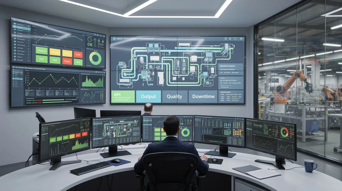
    The image depicts a modern control room filled with multiple monitors that display real-time data related to manufacturing operations management. This setup illustrates the integration of enterprise control systems, enabling efficient monitoring and management of business and manufacturing activities.

    Terminology and Consistency Between IEC 62264 and ISA-95

    One of the key aims of both IEC 62264 and ISA-95 is to provide a stable, shared vocabulary for enterprise-control system integration. This interface terminology allows different organizations to describe the same operations the same way.

    The two series coordinate on terminology for key concepts:

    Term

    Definition

    Manufacturing Operations Management

    Level 3 functions that manage manufacturing operations

    Process segment

    A logical grouping of manufacturing operations

    Material lot

    A specific quantity of material with common properties

    Equipment

    Physical assets used in manufacturing

    Work center

    A grouping of equipment for production purposes

    Production schedule

    A plan for production activities over time

    Revisions such as those in IEC 62264-3:2016 have explicitly updated terms to align with naming conventions in other parts (for example, IEC 62264-4) and with their ISA-95 counterparts. This deliberate alignment ensures models and terminology remain consistent across the entire standard family.

    This terminology consistency allows documentation, system specifications, and cross-site process descriptions to remain coherent whether a stakeholder references the ISA or IEC designation. When different parties in a supply chain use the same terms for the same concepts, integration becomes more straightforward.

    Connect981 uses this standards-aligned vocabulary in its data model and user interfaces where practical. This helps aerospace and MRO organizations describe the same operations the same way across OEMs, suppliers, and regulators.

    Role of International Standardization in Manufacturing Operations

    International standardization through bodies like the IEC enables manufacturers, technology providers, and regulators across different regions to share a common framework for describing manufacturing operations. This role is especially important for industries with global supply chains.

    IEC 62264 supports interoperability by giving different systems a shared reference for how information should be structured at the boundaries between business and manufacturing. When an ERP system needs to communicate with an MES, or when an MES needs to exchange data with a QMS, IEC 62264 provides the conceptual framework for describing what information should flow and how it should be structured.

    In global aerospace supply chains, this international alignment is crucial for coordinating:

    • Production schedules across multiple manufacturing sites
    • Quality data shared between OEMs and suppliers
    • Maintenance records for aircraft components across MRO providers
    • Compliance documentation required by different regulatory authorities

    International standards make it easier for software platforms to interoperate with existing systems. Because the information flows can be modeled using widely understood IEC 62264 and ISA-95 concepts, integration projects can proceed from a shared reference point rather than custom definitions.

    IEC 62264’s role is to provide a neutral, well-defined language for manufacturing operations. This supports long-term consistency even as specific technologies, architectures, and tools evolve. The standard organizes technology choices without mandating them.

    IEC 62264, Smart Manufacturing, and Aerospace Digital Operations

    IEC 62264’s models connect directly to current themes such as smart manufacturing, Industry 4.0, and connected aerospace operations. The standard’s technology-agnostic architecture remains valid as organizations adopt new capabilities.

    Similar to ISA-95, IEC 62264 offers an architecture that accommodates:

    • IoT devices and sensor networks at Levels 0-2
    • Cloud analytics and reporting systems
    • AI-driven insights and predictive analytics
    • Digital thread initiatives connecting design through production
    • Automation across manufacturing and quality processes

    Aerospace and MRO organizations can use IEC 62264 concepts to describe how information should move between:

    • Planning systems: Build plans, maintenance programs, production schedules
    • Operations systems: Work execution, inspections, resource allocation
    • Supporting systems: Configuration management, certification records, audit trails

    The hierarchical model and activity models provide a stable reference even as the underlying technology changes. An organization can modernize its industrial control systems, adopt new information technology platforms, or implement advanced automation while maintaining alignment with the same conceptual framework.

    Platforms like Connect981 implement digital work instructions, traceability, supplier collaboration, and real-time reporting in ways that fit naturally into the Level 3 Manufacturing Operations Management space described by IEC 62264-3. This alignment provides several advantages:

    • Clear boundaries between what enterprise systems manage and what shopfloor systems manage
    • Consistent terminology for describing product offerings and system capabilities
    • A reference for how information should flow between applications performing business functions and those managing physical production

    By aligning digital operations platforms with IEC 62264 and ISA-95 concepts, aerospace manufacturers and MRO providers can modernize their operations while keeping a clear, standards-aligned structure for information and responsibilities. The result is operations that increase uniformity across sites and suppliers without requiring all parties to use identical technology platforms.

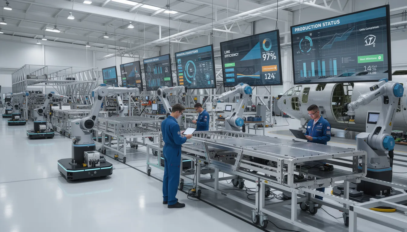
    The image depicts an aerospace manufacturing facility featuring digital displays that showcase real-time production information, reflecting the integration of control systems and manufacturing operations management systems. This environment emphasizes the importance of enterprise control system integration and efficient management of manufacturing activities.

    IEC 62264 provides the neutral, well-defined language that global aerospace manufacturing operations require. Its conceptual mirroring of ISA-95 ensures that organizations referencing either designation work from the same technical foundation. For aerospace teams coordinating production, maintenance, quality, and supply chain activities related to complex product offerings, this standards alignment supports consistent communication across other domains and systems.

    Connect981 is designed with these IEC 62264 and ISA-95 concepts in mind, organizing digital aerospace manufacturing and MRO workflows around the same levels, objects, and activities that the standards describe. To see how this standards-aligned approach works in practice, request a demo and explore how Connect981 fits into your operations architecture.

  • What is ISA-88? A Practical Overview of the Batch Control Standard

    What is ISA-88? A Practical Overview of the Batch Control Standard

    What is ISA-88?

    ISA-88, formally known as ANSI/ISA-88.01-1995 and also referenced as S88 or IEC 61512, is an international standard that defines models and terminology for batch control in manufacturing processes. The standard originated from the work of the International Society of Automation (ISA) SP88 committee in the early 1990s, driven by the need for a consistent set of concepts that could be applied across plants, vendors, and automation platforms. Rather than prescribing specific control algorithms or batch control software configurations, ISA-88 provides a structured framework for describing how batch processes work, how equipment is organized, and how recipes translate product requirements into executable procedures.

    The standard was developed primarily for batch process industries such as pharmaceuticals, specialty chemicals, food and beverage, and biotechnology. However, the underlying concepts have proven useful in any manufacturing environment where finite quantities of material are produced through defined sequences of processing activities on shared or reusable equipment. ISA-88’s main contribution is the conceptual separation of recipe, equipment, and process, which provides a common language for control engineers, IT teams, operations personnel, and management. This separation allows organizations to describe what they make, where they make it, and how they make it as distinct but connected concerns.

    Connect981 works with manufacturers that often rely on ISA-88 concepts to structure their batch documentation, traceability, and shopfloor workflows, even when control systems differ across sites or supplier facilities. The models and terminology defined by the standard offer a foundation for consistent communication regardless of the specific batch automation platforms in use.

    Batch Manufacturing and Batch Control Context

    Batch production involves creating finite quantities of material by subjecting inputs to an ordered sequence of operations over a defined period, typically using equipment that can be reconfigured or reused for different products. This stands in contrast to continuous processing, where material flows through a plant without discrete start and stop points, as in large petroleum refineries or paper mills. It also differs from one-off discrete manufacturing, such as custom fabrication of a unique part, where each item may follow a distinct path.

    Many regulated and high-mix environments rely on batch logic. Pharmaceutical manufacturing, for example, produces defined lots of tablets or injectable solutions where every batch must meet strict quality specifications. Chemical processors run different formulations through shared reactors and separators. Food manufacturers produce finite runs of different product recipes on the same filling and packaging lines. In each case, batch operations coordinate what happens, when it happens, and on which equipment, covering activities such as charging materials, heating, holding, reacting, cooling, and discharging.

    The image depicts an industrial batch processing facility featuring stainless steel reactor vessels and mixing tanks, essential components in batch production. This environment highlights the use of batch control systems and automated control systems for efficient process operations and regulatory compliance in manufacturing.

    In life sciences and aerospace-related special processes, the batch concept extends to operations like composite curing, surface treatment baths, and heat treatment cycles. These batches must be tightly controlled and fully traceable to support regulatory compliance and product quality. ISA-88 provides a consistent way to model this complexity so that procedures, equipment capabilities, and recorded batch data remain aligned and auditable across different sites, systems, and even supplier networks.

    Purpose and Scope of the ISA-88 Standard

    The primary goal of ISA-88 is to define a common set of models and terminology for batch control that can be applied consistently across plants, control systems, and suppliers. Before the standard existed, batch automation was often implemented using custom, plant-specific software that made it difficult to transfer processes between sites, communicate requirements to automation vendors, or integrate systems from different manufacturers.

    ISA-88 addresses these challenges by improving efficient communication between process engineering, automation, IT, and operations teams. The standard enables modular, reusable design of batch procedures, meaning that a well-defined phase or operation can be deployed across multiple products without being rewritten for each application. It also supports regulatory compliance by providing structured data structures for batch production records, making it easier to demonstrate traceability and process consistency during audits.

    The ISA-88 standard is organized into multiple parts. Part 1 establishes the core models and terminology. Part 2 covers data structures and guidelines for languages used to represent batch logic. Part 3 extends the recipe framework to general and site recipe models that support multi-site standardization. Part 4 defines a data model for batch production records, capturing materials, activities, and process conditions. Part 5 addresses modular concepts for automated control systems, applying ISA-88 principles to reusable automation components. These parts are discussed in more detail later in this article.

    The boundaries of the standard’s scope are deliberate. ISA-88 focuses on batch control models and data structures, not on mechanical design, detailed safety interlock systems, or business planning logic. It is also technology-agnostic: the concepts apply whether batch control is implemented on PLCs, DCS platforms, SCADA systems, MES layers, or custom batch engines. Higher-level coordination may use modern platforms like Connect981 or legacy tools, and the ISA-88 framework remains applicable in either case.

    Core ISA-88 Models and Terminology

    ISA-88 defines a set of abstract models that describe batch processes from multiple perspectives. These include the process model, the physical model, and the procedural control model, along with standardized terminology such as process cell, unit, phase, and recipe. Each model provides a different view of the same manufacturing reality. The process model focuses on the scientific and chemical requirements of what must happen to the material. The physical model describes the equipment hierarchy that exists in the plant. The procedural control model captures how operations are executed over time, connecting process requirements to physical resources.

    These models give multidisciplinary teams a shared framework for discussing batch operations without getting lost in vendor-specific control code or hardware details. The following subsections introduce each model and its key components.

    ISA-88 Process Model

    The process model describes the manufacturing process in terms of what needs to happen to the material, independent of specific physical equipment. It uses a hierarchy of process, process stages, process operations, and process actions. At the top level, a process represents the complete set of steps required to transform raw materials into a final product. For example, in pharmaceutical manufacturing, this might encompass everything from raw active ingredients and excipients through to compressed tablets ready for packaging.

    Process stages break the overall process into major segments that are meaningful to process engineers and quality teams. These might include stages such as solution preparation, reaction, purification, and finishing. Each stage represents a significant portion of the overall transformation without yet specifying which tanks, reactors, or dryers will be used.

    Process operations and process actions allow further refinement. Operations capture logical steps within a stage, while actions represent elementary tasks such as charging solvent, heating to a setpoint, agitating, or holding for a defined reaction time. Throughout this hierarchy, the process model remains equipment-agnostic. This allows organizations to define a common process description that can later be mapped onto different physical installations, whether at a headquarters plant, a contract manufacturer, or a supplier facility. In aerospace-related special processes, the process model might capture stages like surface preparation, coating application, cure, and post-cure inspection, without assigning specific ovens or spray booths.

    ISA-88 Physical Model

    The physical model represents the real equipment hierarchy that exists in a manufacturing facility. ISA-88 defines levels including enterprise, site, area, process cell, unit, equipment module, and control module, though batch control typically focuses on the levels from process cell downward.

    The image depicts a factory floor filled with various processing equipment, including reactors, mixers, and control panels, essential for batch production and automation. This environment showcases the integration of batch control systems and equipment modules that support efficient process operations and regulatory compliance.

    A process cell is a collection of control equipment arranged to produce one or more products. For example, a pharmaceutical process cell might include a set of reactors, filters, and dryers that can be combined in various configurations to run several different recipes. The process cell is the scope within which batch control coordinates activities.

    Units are major pieces of physical equipment capable of carrying out unit procedures. A reactor vessel, blending tank, granulator, or autoclave would each be considered a unit. In the standard model, each unit operates on one batch at a time, making it a natural boundary for procedural execution and traceability.

    Equipment modules represent functional groupings within or across units. A dosing skid, heating loop, or clean-in-place module would be examples. Control modules sit at the lowest level and include individual devices like valves, motors, sensors, and measurement instruments. These are the components that receive basic control commands and provide feedback to higher-level logic.

    The physical model allows batch designers to reason about what each part of the plant can do, independent of any specific recipe. This makes it easier to reuse units or modules across many products and to understand capacity constraints when scheduling batch production. While ISA-88 was created for control systems, the same physical structure proves useful in higher-level digital tools for mapping work instructions, traceability, and maintenance records onto specific units and modules.

    ISA-88 Procedural Control Model

    The procedural control model describes how a batch is executed over time, using a hierarchy of procedure, unit procedure, operation, and phase. A procedure represents the complete set of steps needed to run a batch, mapped to a process cell. A unit procedure is a logical segment tied to a specific unit, such as a charging and reacting sequence that takes place entirely within a single reactor.

    Operations divide unit procedures into smaller logical steps. Phases are the smallest procedural elements, directly interacting with equipment modules and control modules. A phase might represent actions such as starting an agitator, heating and holding at a setpoint, or transferring material to a buffer tank. Phases are where sequential control and regulatory control commands are typically applied to the physical equipment.

    The procedural control model is where the separation between recipe logic and equipment capability becomes operational. The same unit might support phases used by multiple different recipes. A reactor that can heat, cool, agitate, and transfer can execute phases for dozens of products without requiring new control logic for each one.

    ISA-88 also defines standard execution states and transitions for phases and units. These include quiescent states like idle and held, transient states representing transitions, and final states indicating completion. The standard provides guidelines for unit states without prescribing PLC programming patterns or specific vendor implementations. This allows multidisciplinary teams to discuss sequence behavior and exception handling using common terminology.

    Consider a simple unit procedure: charge materials, heat to reaction temperature, hold for reaction time, cool to discharge temperature, transfer to the next unit. This sequence illustrates how the procedural control model organizes activities without specifying the exact valve sequences or controller settings that would vary by installation.

    Separation of Recipe, Equipment, and Process in ISA-88

    One of ISA-88’s defining principles is the clear separation of three concerns: what must happen to the material (process), what physical resources exist (equipment), and how a specific product is made at a given site (recipe). This separation allows each concern to be managed, documented, and changed somewhat independently.

    ISA-88 defines several recipe types that sit on top of the process and physical models. A general recipe describes a product at a high level, independent of any specific site. A site recipe adapts that general recipe to the capabilities and constraints of a particular manufacturing location. A master recipe adds equipment-specific details for a particular process cell or set of units. A control recipe is the actual executable instance created for a single batch, containing specific parameter values, material quantities, and equipment assignments.

    The process model expresses product and chemistry requirements. The physical model describes available units and modules. Recipes bind these two worlds together for a specific product on specific equipment. Recipe management becomes a structured activity rather than ad-hoc customization of control code.

    This separation creates practical benefits for organizations. Moving a recipe between sites with different equipment layouts becomes a matter of adapting the recipe at the appropriate level rather than rewriting control logic from scratch. Introducing new equipment modules does not require rethinking the entire product definition if the module can support the required phases. Change control and validation in regulated industries become more tractable when process intent, equipment capability, and recipe parameters are documented in aligned but distinct structures.

    Consider scaling a biotech fermentation process from a pilot plant to commercial production. The process model describes the fermentation requirements: media preparation, inoculation, growth phase, harvest. The pilot plant has one set of units with specific volume and control capabilities. The commercial plant has larger fermenters with different instrumentation. By maintaining the separation, the organization can adapt recipes to the new physical model without changing the underlying process definition.

    In aerospace and MRO operations, many special processes and repair routes follow similar patterns. Process requirements remain stable, specifying what must happen to achieve required material properties or surface conditions. Equipment assignments and control recipes may vary between in-house facilities, approved suppliers, or partner locations. The ISA-88 framework provides a conceptual structure for managing this variation while maintaining traceability and compliance.

    What ISA-88 Standardizes (and What It Does Not)

    ISA-88 standardizes how to describe batch processes, equipment, procedures, and data. It does not standardize how to program or configure specific batch control systems. This distinction is fundamental to understanding the standard’s role and limitations.

    What ISA-88 Standardizes

    What ISA-88 Does Not Standardize

    Common terminology for batch control objects

    Specific PLC, DCS, or MES configurations

    Conceptual models (process, physical, procedural)

    Control algorithms or tuning parameters

    Types and structure of recipes

    User interface layouts or alarm designs

    High-level data structures and relationships

    Enterprise planning logic (scheduling, capacity)

    Concepts for batch production records

    Vendor-specific file formats

    Modular automation concepts

    Manual processes implementation details

    Functional model guidelines

    Data acquisition system specifics

    The standard provides guidelines rather than rigid specifications. It establishes that a control recipe should contain a header, formula, equipment requirements, and procedure, but it does not dictate the database schema or file format used to store that information. It defines what regulatory control and basic control mean in a batch context, but it does not provide guidelines on specific tuning approaches or controller selection.

    This deliberate boundary allows ISA-88 to remain stable and vendor-neutral while giving suppliers and manufacturers freedom to innovate implementations. Organizations often map ISA-88 structures onto their own databases, MES systems, or digital operations platforms to maintain consistency from control logic through documentation and traceability without enforcing a single control technology. Connect981, for example, helps organizations structure shopfloor workflows and documentation in ways that align with ISA-88 concepts even when underlying batch control software varies across sites.

    The standard is just a standard: a conceptual framework rather than a turnkey solution. Its value lies in widespread adoption of common terminology and models that enable smooth integration across disciplines, vendors, and organizational boundaries.

    Relationship Between ISA-88 and ISA-95

    ISA-95 is a companion standard focused on integrating enterprise systems and control systems. While ISA-88 addresses the structure of batch control at the equipment and process cell level, ISA-95 defines models for how information flows between higher-level business systems (ERP, planning, MES) and lower-level control environments.

    The image depicts an overview of a manufacturing facility, showcasing a control room alongside the production floor, illustrating different operational levels within the batch production process. This setting emphasizes the integration of automated control systems and batch control software, essential for managing batch processes and ensuring regulatory compliance in production operations.

    In terms of the Purdue reference model, ISA-88 primarily addresses Levels 1 and 2, where batch operations and control logic reside, with some extension into Level 3 for batch supervision. ISA-95 covers Levels 3 and 4, defining production operations management, scheduling, performance analysis, and inventory management. Together, the standards provide guidelines for a cohesive architecture from enterprise planning through shopfloor execution.

    ISA-88 objects such as units, control recipes, and batch production records can be mapped into ISA-95’s production order, production schedule, and production performance models. Joint guidance from ISA working groups, including discussions at the World Batch Forum and related industry events, has clarified how these mappings work in practice.

    Consider a practical example: an ERP system creates a production order for a batch of specialty chemicals. This order, structured according to ISA-95 concepts, is translated into one or more control recipes and batch runs modeled according to ISA-88. As each batch executes, batch data is collected according to ISA-88’s production record concepts. Batch results then feed back as production responses and records into higher-level systems, completing the information loop.

    Connect981 typically operates in the space between ERP/PLM and on-the-floor control, where ISA-95 production models and ISA-88 batch structures both matter. The platform helps organizations orchestrate work, share data with suppliers, and maintain audit-ready histories in ways that respect both standards’ concepts. Seamless integration between these levels is increasingly important as manufacturers pursue digital transformation and require better visibility across operations, quality, and supply chain functions.

    Structure of the ISA-88 Standard Parts

    ISA-88 is a multi-part standard developed over several decades, with parts published and maintained both by ISA and as IEC 61512 standards for international adoption. Understanding the structure helps organizations determine which parts are most relevant to their operations.

    Part 1: Models and Terminology was published in the mid-1990s and remains the foundation of the standard. It defines the core process model, physical model, and procedural control model along with the vocabulary that has become widely adopted across batch industries. Any organization working with ISA 88 batch control should be familiar with Part 1 concepts.

    Part 2: Data Structures and Guidelines for Languages extends Part 1 by describing data models for batch procedures and records. It provides guidance on how to represent batch logic and procedural elements in a structured way that supports implementation across different platforms. While more technical than Part 1, Part 2 is valuable for teams designing batch control software architectures or MES integrations.

    Part 3: General and Site Recipe Models and Representation expands the recipe framework above the master and control recipe levels. It addresses how organizations can define recipes at corporate or general levels and then adapt them for specific sites, supporting multi-site standardization and technology transfer. This part is particularly relevant for large organizations with multiple manufacturing locations or extensive contract manufacturing networks.

    Part 4: Batch Production Records defines a data model for capturing and storing batch histories, including activities, materials, and process conditions. This part directly supports regulatory compliance requirements in industries like pharmaceuticals, where complete batch records are mandatory for product release. The technical report guidance in Part 4 helps organizations design systems that capture the right information in auditable formats.

    Part 5: Modular Concepts for Automated Control Systems applies ISA-88 concepts to modular, reusable automation components. This part extends the standard builds beyond traditional batch process industries to address modular equipment and plug-and-play automation scenarios that are increasingly common in flexible manufacturing.

    The IEC 61512 series represents the international adoption of ISA-88, with only minor technical differences between the ISA and IEC versions. Global manufacturers often reference the IEC designation in their documentation, particularly when working with European suppliers or regulatory bodies.

    Organizations rarely implement all of ISA-88 at once. Most selectively apply models and recipe concepts that align with their products, regulatory requirements, and legacy batch systems. The modular nature of the standard supports this approach, allowing organizations to adopt terminology and models progressively as their batch operations mature.

    For organizations managing complex batch operations across aerospace, pharmaceutical, or chemical industries, understanding ISA-88 provides a common language that bridges engineering, operations, and compliance. Connect981 helps teams put these concepts into practice through digital work instructions, traceability, and workflow management that align with how batch operations are structured and documented. To explore how your batch documentation and shopfloor workflows can benefit from this structured approach, request a demo to see the platform in action.

  • ISO 22400 Manufacturing KPIs: Standardized Performance Measurement for Modern Plants

    ISO 22400 Manufacturing KPIs: Standardized Performance Measurement for Modern Plants

    Answer First: What ISO 22400 Means for Manufacturing KPIs

    ISO 22400 is an international standard that defines how key performance indicators should be structured, named, and conceptualized for manufacturing operations management. Published by the International Organization for Standardization beginning in 2014 and still current in 2025, the standard provides a common language for measuring manufacturing performance across plants, enterprises, and supply chains. It does not tell manufacturers what to improve or which metrics matter most for their business. It defines what those metrics mean.

    The standard exists because manufacturing companies operating across multiple sites, working with diverse suppliers, and integrating heterogeneous systems need consistent terminology. When one plant reports “availability” and another reports “uptime,” the numbers may not be comparable. ISO 22400 addresses this by providing unambiguous definitions for key performance indicators KPIs used in production, maintenance, quality, and related operations. The goal is interoperability and clarity, not performance coaching.

    This article focuses on conceptual definitions, KPI categories, and the limits of KPI standardization as framed by ISO 22400. It does not explain how to calculate KPIs, recommend which KPIs to use, or offer advice on performance improvement. Connect981 uses ISO 22400 concepts to keep aerospace and MRO reporting aligned with global terminology, while integrating with ERP, MES, PLM, and QMS. The platform applies standardized definitions where feasible without mandating any particular KPI set for its users.

    The image depicts an industrial factory floor filled with automated machinery and advanced control systems, showcasing the integration of manufacturing operations management and automation systems. This environment emphasizes production efficiency and overall equipment effectiveness, essential for achieving key performance indicators in the manufacturing industry.

    ISO 22400 in Context: Purpose, Scope, and Relationship to Other Standards

    ISO 22400 belongs to the automation systems and integration family of standards. Its primary focus is establishing an industry neutral framework for key performance indicators applied to manufacturing operations management. The standard addresses how KPIs should be defined, composed, exchanged, and utilized across different automation systems and software platforms.

    The standard consists of multiple parts:

    • ISO 22400-1:2014 provides the foundational concepts and terminology. It introduces a framework for KPIs that can apply across batch, continuous, and discrete industries without prescribing specific metrics for any sector.
    • ISO 22400-2:2014 defines a set of 34 KPIs drawn from current industry practices. Each KPI includes attributes such as its description, applicable time behavior, units of measure, logical ranges, and trend direction. The intent is conceptual clarity, not formula delivery.

    The standard aligns with IEC 62264-1, which addresses enterprise-control system integration. Both standards reference similar hierarchical levels: enterprise, site, area, work center, and work unit. ISO 22400 KPIs are primarily positioned at Level 3 of this hierarchy, focusing on production, quality, inventory, and maintenance operations. Level 4 metrics, which incorporate economic, logistic, and financial factors tied to business planning, fall outside the standard’s scope.

    ISO 22400 is designed to be applicable across the manufacturing industry broadly. Aerospace, automotive, electronics, and process industry operations can all reference the same KPI definitions. This neutrality supports organizations that operate across multiple sectors or collaborate with suppliers in different verticals.

    • The standard supports interoperability among heterogeneous systems (ERP, manufacturing execution systems, SCADA, historians, and reporting tools) by standardizing KPI names, definitions, and data relations. When two systems use the same ISO 22400 definition for a metric, their data can be compared or aggregated without manual translation.

    Conceptual Definitions: From Performance Measurement to Manufacturing KPIs

    Performance measurement in a manufacturing context refers to the systematic quantification of efficiency, effectiveness, and resource utilization using structured metrics. The purpose is to provide a comprehensive view of how production processes, equipment, and personnel behave over a specific period. ISO 22400 provides the conceptual foundation for this measurement activity.

    The standard works with several core definitions:

    • Performance indicator: A measurable representation of how a process, system, or resource behaves over time. Indicators provide quantifiable data points that describe operational states or outcomes.
    • Key performance indicator (KPI): A selected subset of performance indicators considered critical for understanding manufacturing operations. KPIs are framed in a standardized way, with explicit definitions of what they measure, how they relate to time and quantity elements, and who typically uses them (operators, supervisors, management).
    • Manufacturing operations management (MOM): The set of activities that plan, dispatch, execute, track, and report manufacturing and maintenance operations. MOM sits between enterprise planning (ERP) and basic control systems, managing manufacturing operations at the execution level.

    ISO 22400 emphasizes unambiguous terminology. Terms such as “availability,” “utilization,” “work unit,” “production order,” and “state” each have precise definitions. This precision keeps KPIs interpretable across plants and suppliers. When a contract references “equipment utilization” as defined in ISO 22400, both parties can verify they mean the same thing.

    The standard distinguishes between different levels of data abstraction:

    Level

    Description

    Example

    Raw signals

    Direct outputs from equipment or control systems

    Machine ON/OFF, cycle counters, timestamps

    Derived indicators

    Calculated values based on raw signals

    Time in a specific state, produced quantity

    KPIs

    Aggregated indicators mapped to defined concepts

    Equipment utilization, order execution reliability

    ISO 22400 deliberately separates conceptual definitions from implementation details. It defines what a KPI means without specifying which database, SCADA system, or reporting technology must be used. This separation allows manufacturing systems of varying architectures to implement the same conceptual framework.

    KPI Categorization in ISO 22400: How the Standard Structures Manufacturing Metrics

    ISO 22400 groups KPIs to reflect different viewpoints on manufacturing operations. The categorization addresses multiple dimensions: what is being measured, at what level of the organization, over what time horizon, and using what type of underlying data.

    The main categorization dimensions include:

    • Functional domain: KPIs oriented toward production operations, maintenance operations, quality operations, logistics, or energy usage. Each domain addresses a distinct aspect of manufacturing performance.
    • Object of measurement: KPIs can focus on industrial equipment and work units, production lines and areas, work centers, entire plants, or specific production orders and lots. The level of granularity depends on the decision context.
    • Time horizon: Indicators may reflect real time insights, shift-level summaries, daily aggregates, weekly or monthly trends, or the full lifecycle of a production order.
    • State-based vs. quantity-based: Some KPIs measure time in specific states (running, idle, scheduled downtime, unplanned downtime). Others measure volumes such as units produced, accepted units that meet quality standards, or scrap rate.

    Within these dimensions, ISO 22400 defines families of KPIs:

    • Equipment-oriented KPIs focus on machine or work unit behavior. These include concepts related to overall equipment effectiveness, availability indicators, and utilization indicators. The emphasis is on how equipment spends its planned time and actual time.
    • Order and production-related KPIs assess how executed operations compare to planned operations. Metrics in this family address production time structure, cycle time adherence, and throughput relative to production capacity.
    • Resource-related KPIs provide conceptual views on energy consumption, raw materials usage, or personnel involvement tied to specific operations.

    ISO 22400 often expresses KPIs as relationships among time categories, quantities, and events. The 34 KPIs defined in ISO 22400-2 are not isolated metrics. Research highlights their mutual interconnections, meaning changes in one indicator often affect others. This interdependence supports more nuanced analysis but also requires careful interpretation.

    • This categorization helps organizations and software platforms build consistent data models and dashboards. When “availability” or “resource utilization” has the same definition across multiple sites and suppliers, reporting becomes comparable without manual reconciliation.

    The image depicts an automated production line featuring advanced robotic assembly equipment, illustrating modern manufacturing operations management. This setup highlights key performance indicators related to production efficiency and overall equipment effectiveness within the manufacturing industry.

    Analytical View of OEE and Other Equipment-Oriented KPIs in ISO 22400

    ISO 22400 devotes significant attention to equipment-related KPIs because equipment behavior is central to manufacturing performance measurement. How machines spend their time, how much they produce, and whether output meets quality standards are fundamental concerns for any manufacturing plant.

    The standard addresses overall equipment effectiveness OEE at a conceptual level:

    • OEE is expressed through combinations of time-based and output-based indicators. These reflect availability, performance, and quality concepts without prescribing a single calculation method.
    • ISO 22400 introduces multiple OEE-related models, including variants referred to as OEEA and OEEB. These models are constructed from well-defined time elements (such as busy time, operating time, and downtime categories) and material-related quantities (good quantity, defect rate).

    Academic analyses since 2020 have evaluated these models for internal consistency and alignment with traditional TPM OEE concepts. The standard itself remains at the definitional level. It does not mandate how a plant should interpret or act on OEE figures.

    Equipment states serve as a conceptual bridge between control-system events and KPI definitions. ISO 22400 references states such as:

    State

    Description

    RUN

    Equipment actively producing

    STOP

    Equipment halted, not producing

    IDLE

    Equipment available but not currently running

    SLOW

    Equipment running below target speed

    Each state maps to specific time categories defined in the standard. This mapping allows different automation systems to classify equipment behavior consistently and feed that classification into equipment effectiveness indicators.

    The analytical intent of these definitions is threefold:

    1. Provide a consistent vocabulary of equipment states and derived times.
    2. Enable standard mapping from these times to equipment-focused KPIs.
    3. Support interoperability between automation systems and integration platforms when exchanging performance data.

    This section describes how OEE-related KPIs are framed conceptually in ISO 22400. It is not guidance on how to use OEE for continuous improvement or how to identify areas for operational excellence initiatives.

    Limits of KPI Standardization: What ISO 22400 Does Not Decide

    ISO 22400 standardizes definitions and structures. It intentionally avoids prescribing business strategy, objectives, or plant-specific KPI sets. Understanding these boundaries is essential for organizations adopting the standard.

    Key limits of KPI standardization include:

    • Context dependence: The relevance of any KPI depends on industry, process type, regulatory environment, and organizational goals. What constitutes an important KPI for a discrete industries manufacturer may differ from a process industry facility. The standard does not make those determinations.
    • Granularity choices: ISO 22400 defines KPIs across multiple levels (work unit, line, area, plant, production order). It does not state which level should be reported for any given decision process. A production engineering team may need work-unit-level data; a plant manager may need site-level summaries.
    • Weighting and thresholds: The standard defines what a KPI means. It does not set target values, good or bad thresholds, or scoring models. Strategic goals and acceptable performance ranges remain organizational decisions.

    The standard also does not specify:

    • Algorithms for data collection (sampling rates, filtering rules, data validation procedures)
    • Visualization techniques (dashboards, heatmaps, Pareto charts, trend displays)
    • How KPIs should be used in performance reviews, incentive systems, or lean manufacturing programs

    Organizations may combine ISO 22400 KPIs with additional, domain-specific indicators. Aerospace traceability measures, MRO turnaround-time breakdowns, or preventative maintenance scheduling metrics may lie outside the formal scope of the standard but can coexist with ISO 22400 terminology.

    • Connect981 maps plant data into ISO 22400-aligned structures where feasible, while allowing non-standard, aerospace-specific indicators to coexist. These additional indicators are not labeled as ISO 22400 KPIs, maintaining clarity about what is standardized and what is organization-specific.

    The boundaries of standardization are not deficiencies. They reflect a deliberate design choice. ISO 22400 provides vocabulary and structure; organizations fill in the content based on their operational realities.

    ISO 22400 in a Connected Manufacturing Environment: Data, Integration, and Interoperability

    Modern manufacturing plants operate with multiple systems exchanging data: ERP for business planning and order management, MES for production execution, QMS for quality operations, PLM for product definition, historians for time-series data, and various reporting tools for KPI data visualization. ISO 22400 provides a conceptual layer that helps these systems speak a common language when discussing manufacturing performance.

    The role of ISO 22400 in data modeling includes:

    • Providing standard names and definitions for common KPIs across production, maintenance, and quality domains.
    • Aligning time and state concepts so that different systems interpret equipment and order behavior consistently.
    • Supporting manufacturers, system integrators, and software vendors when they design interfaces and data exchanges.

    A platform like Connect981 leverages standardized KPIs in several ways:

    • Mapping incoming signals and events from existing MES and ERP systems to ISO 22400 concepts for managing manufacturing operations.
    • Supporting aerospace and MRO workflows (digital work instructions, parts traceability, quality checks) while keeping KPI semantics consistent with the standard.
    • Enabling multi-site reporting where a KPI such as “equipment utilization” or “production efficiency” is based on the same underlying definitions at every facility.

    ISO 22400 does not require any specific technology stack. No mandated databases, cloud platforms, or UI frameworks appear in the standard. It is designed to be compatible with web-based dashboards, SCADA-based reports, and third-party analytics tools alike. The end user can choose their preferred technology while maintaining definitional consistency.

    • Standardization helps when collaborating with suppliers. Contract reporting can reference ISO 22400 KPI concepts so that both parties interpret metrics the same way, even if they use different internal systems. This reduces disputes over what was measured and how.

    The image depicts an industrial control room filled with multiple monitoring displays, where operators are actively managing manufacturing operations. This environment focuses on key performance indicators (KPIs) related to production performance and overall equipment effectiveness, emphasizing the importance of real-time insights in optimizing manufacturing processes.

    While this connected environment can enable broad performance analysis, ISO 22400 itself remains focused on definitions and structures. It does not prescribe how organizations should improve their operations or which metrics deserve the most attention. Companies tend to adopt the vocabulary and then make their own decisions about application.

    Summary and Implications for Standards-Aligned KPI Frameworks

    ISO 22400 provides a standards-based framework for manufacturing KPIs. Aligned with IEC 62264-1 and applicable across discrete, batch, and continuous industries, the standard offers an industry neutral framework for defining, categorizing, and exchanging performance information. The 34 KPIs in ISO 22400-2 cover production, quality, and maintenance operations with explicit attributes including units of measure, applicable user groups, and trend directions.

    The standard’s value lies in conceptual definitions and KPI categorization. Equipment-oriented indicators, order-related metrics, and resource utilization concepts each have precise meanings that support interoperability across heterogeneous manufacturing systems. The limits of KPI standardization are equally clear: ISO 22400 defines meaning and structure, not targets, calculation algorithms, or management methods. Organizations retain full discretion over which KPIs to monitor, what thresholds to set, and how to act on the resulting KPI data.

    For aerospace manufacturing and MRO environments, mapping digital operations to ISO 22400 concepts helps maintain high standards of clarity and comparability. When multiple plants and suppliers reference the same definitions, performance information becomes actionable across organizational boundaries. Platforms like Connect981 can implement these standardized definitions as part of a broader digital operations layer, while leaving each organization free to decide which KPIs matter for their specific context and how to interpret results. The standard provides the vocabulary; the organization provides the strategy.

  • Manufacturing Operations Management Standards

    Manufacturing Operations Management Standards

    Introduction to Manufacturing Operations Management (MOM)

    Manufacturing operations management sits at the intersection of business planning and shopfloor reality. It represents the coordinated management of production operations between enterprise planning systems and physical process control. Where ERP handles long-term scheduling and resource allocation, and automation systems handle real-time machine control, manufacturing operations management occupies the middle ground: translating business intent into executable work and feeding actual results back up the chain.

    This article focuses specifically on the standards that define and measure manufacturing operations management. The goal is not to recommend software products or propose architectures. Instead, the aim is to walk through the major models and how they relate to one another.

    The term MOM gained traction in the 2000s as ISA-95 and manufacturing execution systems concepts evolved toward a broader operational scope. Before that, manufacturers often referred to MES, SCADA, or various shop floor control systems without a unifying framework. Standards such as ISA-95, IEC/ISO 62264, and ISO 22400 now offer a shared language for MOM functions, data exchanges, and performance indicators. Understanding these standards helps operations teams, engineers, and leadership speak the same language when discussing how production should be managed.

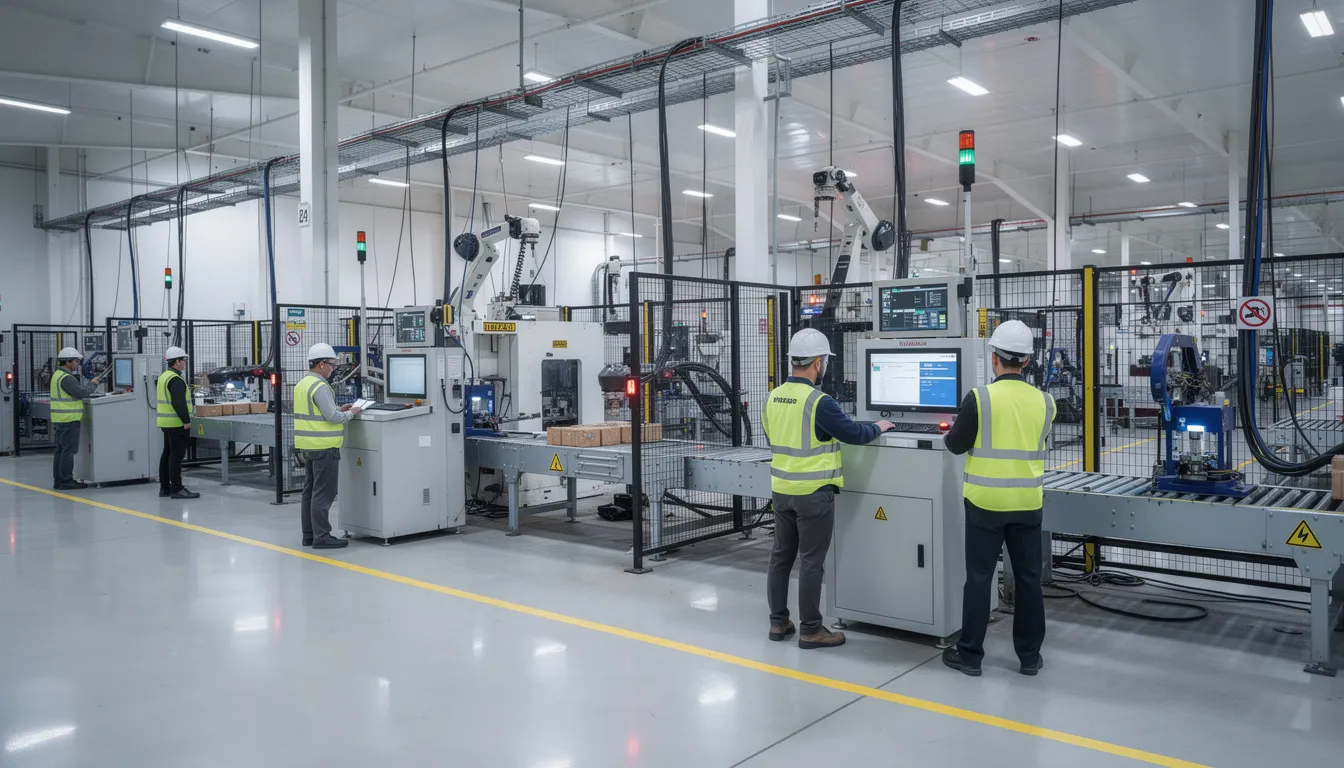
    The image depicts an industrial manufacturing floor bustling with activity, featuring automated equipment alongside workers who are monitoring production lines to ensure operational efficiency. This environment highlights the integration of smart manufacturing and quality management systems, aimed at achieving high-quality products and continuous improvement in manufacturing operations.

    What Is MOM? Definitions, Scope, and Boundaries

    At a high level, manufacturing operations management is the set of activities that manage, monitor, track, and improve manufacturing operations in real time or near-real time. It bridges the gap between what the business wants to produce and what actually happens on the production floor.

    MOM covers several operational domains that together form the entire manufacturing process:

    • Production operations: scheduling, dispatching, and tracking work orders through the production process
    • Quality operations: enforcing quality standards, inspections, and defect logging
    • Maintenance operations: coordinating equipment upkeep, repairs, and reliability tracking
    • Inventory operations: managing raw materials, work-in-progress, and finished goods on the floor

    These domains align with terminology from ISA-95 and IEC 62264, which refer to them as Production Operations Management, Maintenance Operations Management, Quality Operations Management, and Inventory Operations Management.

    The functional boundary between manufacturing operations management and adjacent systems is drawn along three zones:

    Zone

    Function

    Examples

    Planning

    Long-term and aggregate decisions about what to make, when, and with what resources

    MRP, rough-cut capacity planning, demand forecasting in ERP

    Operations Management

    Detailed scheduling, dispatching, resource allocation, and real-time coordination

    Work order management, production scheduling, workforce management

    Control

    Real-time actuation, feedback loops, and machine-level automation

    PLCs, SCADA, DCS, sensor networks

    Standards frame MOM at “Level 3” in the classic automation hierarchy. This places it above real-time control (Level 2) and below business planning (Level 4). The Level 3 boundary is where production efficiency meets business processes. Planning largely happens at Level 4, execution and coordination at Level 3, and closed-loop control at Levels 2 through 0.

    Definitions vary slightly between ISA, ISO, and MESA documents, but all center on the same idea: orchestrating the execution of production in alignment with business plans while collecting performance data to support continuous improvement.

    Why Multiple MOM-Related Standards Exist

    Different standards bodies developed MOM-related specifications to address complementary needs. ISA focused on functional models and integration. IEC and ISO addressed international harmonization and performance measurement. MESA and the World Batch Forum (WBF) historically contributed best practices and batch-specific guidance.

    The timeline helps explain the landscape:

    • ISA-95 Part 1 was first published in 1995, with subsequent parts released through the early 2000s
    • ISA-95 was later adopted as IEC 62264 and subsequently as ISO 62264, creating alignment across international standards bodies
    • ISO 22400, focusing on KPIs for manufacturing operations, was published between 2014 and 2017

    Regional and sector-specific regulations also influenced the proliferation of MOM-adjacent guidance. FDA regulations in life sciences demand traceability and validation. EN standards in Europe address safety and environmental regulations. AS9100 in aerospace requires documented quality management systems and process control.

    The overlapping scopes are intentional. The primary mom standards describe different aspects of the same operational reality:

    Standard

    Primary Focus

    ISA-95 / IEC 62264

    What functions exist and how information flows between levels

    ISO 22400

    How to measure and quantify MOM performance

    ISA-88

    How batch processes should be structured and controlled

    Sector standards (AS9100, IATF 16949)

    Industry-specific quality and compliance requirements

    Convergence efforts exist. The adoption of ISA-95 as IEC/ISO 62264 represents one major unification. However, complete standardization has not been achieved because different use cases and stakeholder communities have distinct priorities. A discrete electronics manufacturer has different needs than a batch pharmaceutical producer. A global supply chain network has different integration challenges than a single-site operation.

    The goal of multiple standards is interoperability and comparability, not vendor lock-in. When organizations reference these standards, they can describe their manufacturing operations using internationally recognized terminology that suppliers, auditors, and partners understand.

    The Role of ISA-95 and IEC/ISO 62264 in MOM

    ISA-95 is the foundational family of standards for describing manufacturing operations management functions and information flows. Developed by the International Society of Automation, its parts were later adopted as IEC 62264 and then ISO 62264. This makes ISA-95 the backbone for discussing what MOM does and how it connects to the rest of the enterprise.

    The main conceptual contributions of ISA-95 and IEC 62264 include:

    • A functional hierarchy spanning Levels 0 through 4
    • Models for production, quality, maintenance, and inventory management
    • Object models defining the data entities exchanged between enterprise and control levels
    • Activity models describing how manufacturing operations are managed

    ISA-95 defines the Level 3 space where a manufacturing operations management system lives. This distinguishes it from enterprise resource planning at Level 4 and automation and control at Levels 0 through 2.

    The key elements of the standard are organized across multiple parts:

    • Part 1: Models and terminology for enterprise-control integration
    • Part 2: Object models and attributes for information exchange
    • Part 3: Activity models of manufacturing operations management
    • Parts 4 and beyond: Object models for integration, batch specifics, and extended scenarios

    MOM in ISA-95 is decomposed into four major domains that cover actual manufacturing operations activities:

    1. Production Operations Management: managing work orders, production scheduling, dispatching, and tracking
    2. Maintenance Operations Management: coordinating equipment maintenance and reliability
    3. Quality Operations Management: enforcing quality control, inspections, and nonconformance handling
    4. Inventory Operations Management: tracking materials through the shopfloor

    These domains work together to ensure that manufacturing processes execute according to plan while adapting to real-time conditions.

    ISA-95 Levels and the MOM Boundary

    The classic ISA-95 levels provide a conceptual stack from business planning down to physical processes:

    Level 4: Business Planning and Logistics This is where ERP, supply chain management, and long-term planning reside. Decisions at this level involve what products to make, in what quantities, and when. Demand forecasting, master scheduling, and financial planning happen here. The time horizon spans days, weeks, or months.

    Level 3: Manufacturing Operations Management This is the MOM layer. Detailed scheduling, dispatching, resource allocation, and real-time tracking occur here. The manufacturing operations management system translates Level 4 plans into actionable work instructions and coordinates production efficiency on the floor. Time horizons range from seconds to shifts to days.

    Level 2: Supervisory Control SCADA systems, HMIs, and supervisory logic operate at this level. They provide operators with visibility into process status and enable manual overrides when needed.

    Level 1: Direct Control PLCs, controllers, and feedback loops manage individual pieces of equipment. They execute setpoints and maintain process parameters.

    Level 0: Physical Process This is the actual production process: machines running, materials flowing, parts being assembled or transformed.

    The boundaries help define responsibilities and data exchanges. Planning decisions flow down from Level 4 to Level 3. Execution instructions flow from Level 3 to Levels 2 through 0. Status, measurements, and production performance flow back up the stack.

    In practice, data can cross levels in near real time. Modern systems architectures apply various integration patterns to enable this. But the logical separation in ISA-95 helps standardize what each layer is responsible for and what information it should provide.

    ISO 22400: KPIs and Metrics for MOM

    ISO 22400 is a series of standards that define key performance indicators and terminology for manufacturing operations management. While ISA-95 describes what functions exist, ISO 22400 describes how to measure them.

    ISO 22400 provides:

    • Definitions of MOM-related terms such as availability, performance, and quality rate
    • Formulas for KPIs, including Overall Equipment Effectiveness (OEE)
    • Guidance on interpreting KPIs for different production contexts

    The standard helps organizations achieve standardized processes for performance measurement. When two plants calculate OEE using ISO 22400 definitions, the results are comparable. This matters for operations leaders managing multi-site operations or tracking improvements over time.

    ISO 22400-2 focuses specifically on KPIs for manufacturing operations and references concepts from ISA-95 and IEC 62264. This alignment ensures that metrics correspond to the operations models defined in those standards.

    Key categories of KPIs in ISO 22400 include:

    Category

    Example KPIs

    Throughput and time

    Cycle time, throughput rate, production time

    Quality

    First-pass yield, defect rate, scrap ratio

    Equipment

    OEE, availability, performance rate

    Maintenance

    MTBF (mean time between failures), MTTR (mean time to repair)

    Inventory

    Stock turns, inventory accuracy

    The position of ISO 22400 in the standards landscape is clear: ISA-95 describes what MOM functions and information objects exist; ISO 22400 describes how to quantify MOM performance. Together, they enable organizations to define operations and measure results using internationally recognized methods.

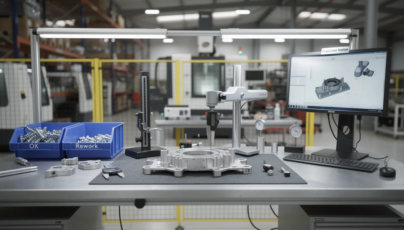
    The image depicts a quality inspection station within a manufacturing facility, featuring various measurement equipment designed to ensure adherence to quality management systems and standards. This setup plays a crucial role in the production process, contributing to operational efficiency and the continuous improvement of product quality.

    Relating ISO 22400 KPIs to ISA-95 MOM Functions

    The relationship between ISO 22400 KPIs and ISA-95 operations domains is direct. Each domain generates data that feeds specific metrics:

    Production Operations Management

    • OEE captures availability, performance, and quality in a single metric
    • Throughput and cycle time measure production process speed
    • Production scheduling adherence tracks plan versus actual

    Maintenance Operations Management

    • MTBF indicates equipment reliability
    • MTTR measures how quickly issues are resolved
    • Planned versus unplanned maintenance ratios show maintenance management maturity

    Quality Operations Management

    • First-pass yield measures how often products pass inspection without rework
    • Defect density tracks quality issues per unit or batch
    • These metrics support quality improvement initiatives and audit readiness

    Inventory Operations Management

    • Stock turns indicate how efficiently inventory moves through the system
    • Inventory accuracy measures alignment between records and physical counts
    • These metrics help reduce waste and avoid excess inventory

    Conceptually, ISA-95 defines the activities generating data, while ISO 22400 defines how to transform that data into comparable indicators. Using both standards together allows organizations to describe both process structure and performance measurement using consistent terminology.

    This combination supports real time data collection and analysis for operational excellence. When mom systems collect data aligned with ISA-95 models and calculate KPIs per ISO 22400 definitions, the resulting manufacturing intelligence is consistent and actionable.

    Other Standards and Reference Models Touching MOM

    Several additional standards intersect with the MOM layer without being MOM definitions themselves. These shape how MOM processes must behave to ensure quality, safety, and compliance.

    ISA-88 (Batch Control) ISA-88 provides models for batch process structuring. It defines procedures, units, equipment modules, and recipes. In batch industries such as pharmaceuticals, food and beverage, and specialty chemicals, ISA-88 models integrate with ISA-95 production operations management. The recipe and procedure structures from ISA-88 feed into MOM scheduling and execution.

    ISO 9001 (Quality Management Systems) ISO 9001 establishes requirements for quality management systems. It influences how MOM quality processes are designed, documented, and audited. Traceability, process control, and continuous improvement requirements in ISO 9001 translate into MOM activities.

    Sector-Specific Standards Relevant international mom standards from specific industries add compliance requirements:

    • IATF 16949 for the automotive sector mandates process control and traceability
    • AS9100 in aerospace requires documented standard operating procedures and audit trails
    • FDA 21 CFR Part 11 in life sciences demands electronic record integrity

    OPC UA Companion Specifications Broader industrial interoperability efforts reference ISA-95 models. OPC UA companion specifications provide standardized data models that align with ISA-95 object models. This enables mom software and control systems to exchange data using consistent structures.

    These standards are not MOM definitions per se, but they shape what MOM must accomplish. When regulatory requirements demand traceability, risk management, or documentation, MOM processes must deliver. When customer expectations require high quality products and on-time delivery, MOM must coordinate production to meet those goals.

    Boundaries Between Planning, MOM, and Control in Practice

    Standards collectively draw lines between three zones of manufacturing management. Understanding these boundaries helps teams align their systems and processes without overlap or ambiguity.

    Planning (Level 4) Planning involves longer-term, aggregate decisions. What products should be made? In what quantities? When? What resources are available across the entire supply chain? Chain management and demand forecasting happen here. Planning decisions flow down to MOM as production orders, schedules, and master data.

    Manufacturing Operations Management (Level 3) MOM handles short-term, detailed coordination. It takes planning inputs and translates them into specific work orders, production scheduling, dispatching, and resource allocation. MOM coordinates workforce management, tracks production efficiency, and manages quality control activities. Results flow back up to planning as production performance, consumption data, and quality reports.

    Control (Levels 0-2) Control manages real-time actuation and feedback. PLCs execute setpoints. Sensors report status. Control loops maintain process parameters. MOM sends detailed work instructions and setpoints down to control. Control sends status and measurements back up to MOM.

    Using terminology from ISA-95, typical data exchanges include:

    Direction

    Data Types

    Level 4 → Level 3

    Demand, master data, production schedules, resource plans

    Level 3 → Level 4

    Production performance, consumption, quality results, inventory status

    Level 3 → Level 2-0

    Work instructions, setpoints, recipes, dispatch orders

    Level 2-0 → Level 3

    Equipment status, measurements, process data, completion signals

    Standards generally avoid mandating specific systems architectures. Instead, they define business processes, interfaces, and information models that can be realized in many ways. This allows organizations to choose the right mom solution for their context while maintaining compatibility with partners and supply chain stakeholders.

    Respecting these conceptual boundaries helps organizations avoid overlap when adopting multiple standards. ISA-95 defines structure. ISO 22400 defines measurement. Sector standards define compliance requirements. Together, they form a coherent picture of how manufacturing operations management connects to the rest of the manufacturing stack.

    When flexible manufacturing operations management aligns with these standards, organizations gain operational efficiency, reduce waste, and achieve effective collaboration across sites and suppliers.

    The image depicts an aircraft maintenance hangar where technicians are actively engaged in servicing a commercial aircraft, showcasing a manufacturing environment focused on quality management and operational efficiency. The scene highlights the collaboration and adherence to standard operating procedures essential for maintaining high-quality products in the aviation industry.

    How Aerospace and MRO Operations Use MOM Standards (Contextual View)

    Highly regulated sectors such as aerospace manufacturing and maintenance, repair, and overhaul (MRO) rely on MOM-aligned practices to meet stringent compliance requirements. AS9100, FAA, EASA, NADCAP, and ITAR regulations demand documented processes, traceability, and audit-ready operations.

    In these environments, the primary mom standards applied to core operational challenges include:

    Production Operations Management Configuration control and build sequence integrity are critical. Work orders must track exactly which parts, at which serial numbers, were installed in which assemblies. Lean manufacturing principles combined with standardized MOM processes help maintain overall operational efficiency while meeting compliance requirements.

    Quality Operations Management First article inspection, in-process checks, and final acceptance all generate quality records. These feed into quality management and support audit trails required by AS9100 and FAA oversight. Advanced analytics on quality data can identify trends and support quality improvement before issues escalate.

    Inventory Operations Management Serialized part traceability spans the global supply chain network. Organizations must track raw materials from receiving through consumption. Multi-tier supplier coordination requires shared visibility into inventory status and material certifications.

    Maintenance Operations Management In MRO operations, maintenance management includes tracking component histories, managing repair cycles, and documenting compliance with airworthiness directives. MTBF and MTTR metrics from ISO 22400 apply directly to fleet reliability analysis.

    Organizations in aerospace and MRO often implement ISA-95/IEC 62264 models alongside ISO 22400 KPIs. This combination supports data analytics for improved safety and resource efficiency. Digital transformation in these sectors means aligning digital operations platforms with MOM standards to ease integration and reporting.

    Current industry discussions in aerospace increasingly focus on how mom systems can support smart manufacturing initiatives while maintaining compliance. The challenges identified include integrating existing systems, managing incremental improvements without disrupting production, and ensuring that digital workflows achieve competitive advantage through better data rather than just automation.

    When digital operations platforms align their data structures and workflows with MOM standards, organizations can more easily connect ERP, MES, supplier portals, and quality systems. This alignment supports cost reduction through reduced rework, waste reduction through better visibility, and customer satisfaction through reliable delivery.

    The standards provide a shared vocabulary. Implementation provides the value. Understanding where manufacturing operations management sits in the hierarchy helps aerospace operations teams align production planning, execution, and measurement while meeting the regulatory requirements that define their industry.

    For aerospace manufacturers and MRO organizations navigating these standards, the path forward involves understanding how MOM concepts apply to your specific operations, compliance requirements, and supply chain complexity. The standards exist to enable consistency and interoperability. The work lies in translating those frameworks into practical workflows that deliver operational excellence on the shopfloor.

  • OPC UA Industrial Interoperability

    OPC UA Industrial Interoperability

    Answering the Core Question: What Is OPC UA and Why Does Interoperability Matter?

    OPC UA, or OPC Unified Architecture, is an interoperability standard developed by the OPC Foundation and first released around 2008. Formalized as IEC 62541, it provides a vendor-neutral, platform independent framework for exchanging industrial data between controllers, equipment, software applications, and enterprise systems. Unlike earlier approaches that tied data exchange to specific operating systems or hardware, OPC UA was designed from the start to work across diverse systems, from embedded controllers running on ARM processors to cloud platforms handling enterprise analytics.

    OPC UA is not just a protocol. It combines communication services with information modeling, defining both how data moves between systems and what that data means. This distinction matters. Many protocols can transfer bytes between two endpoints, but OPC UA goes further by providing a structured way to describe the context, relationships, and semantics of the data value being exchanged. A temperature reading, for example, carries not just a number but metadata about its source, units, quality, and timestamp.

    Industrial interoperability refers to the ability of heterogeneous systems, including PLCs, DCS, scada systems, MES, ERP, analytics platforms, and cloud platforms, to understand and use each other’s data without requiring custom one-off interfaces. In modern industrial contexts such as Industry 4.0 and the industrial internet of things, this capability has become essential. OPC UA’s main conceptual contribution is a common language for data across operational technology and it systems. For aerospace and MRO operations, where reliable traceability, quality, and regulatory compliance are non-negotiable, interoperability is not a convenience but a prerequisite.

    The image depicts a modern industrial factory floor bustling with various automated machines and advanced control systems, showcasing the integration of OPC UA technology for reliable data exchange and industrial automation. The scene highlights the use of diverse systems and sensors, reflecting the principles of Industry 4.0 and the importance of standardized data in process control.

    From OPC Classic to OPC UA: Evolution Toward Interoperability

    The original OPC standard, sometimes called OPC Classic, emerged in the mid-1990s. At that time, “OPC” stood for “OLE for Process Control,” reflecting its roots in Microsoft’s OLE and COM technologies. OPC Classic was designed primarily to connect Windows-based HMIs and scada systems to process control equipment. For its era, it solved a real problem: before OPC, every integration between a PLC and a visualization system required custom drivers.

    Limitations of OPC Classic:

    Constraint

    Impact

    Windows dependency

    Could not run on Linux, embedded devices, or non-Windows platforms

    COM/DCOM complexity

    Firewall configuration and network security were difficult

    Fragmented specifications

    Separate standards for data access (opc da), historical access, and alarms

    Weak security model

    Not aligned with modern expectations for encryption and authentication

    By 2003, industry groups and the OPC Foundation recognized that a new approach was needed. The goals were clear: cross-platform support for ARM, x86, Windows, Linux, and embedded systems; secure communications with encryption and user authentication; and richer context for industrial data. The result was OPC UA, which unified earlier OPC specifications into one extensible architecture and introduced a modern, service-oriented design.

    OPC UA marked a shift from signal-level connectivity to information-level interoperability. Rather than simply moving data points between two systems, OPC UA enables those systems to understand the structure and meaning of what they exchange. Today, OPC UA support is embedded in industrial devices and software products across discrete manufacturing, process industries, energy, and building automation, making it a de facto reference for reliable data exchange.

    Core Concepts of OPC UA: Services, Models, and Neutrality

    Understanding OPC UA requires grasping a few foundational ideas that distinguish it from simpler protocols.

    Service-Oriented Architecture

    OPC UA defines a set of standardized services that any compliant implementation must support. These services include reading and writing data, subscribing to changes, browsing structures, calling methods, and publishing events. The specification describes what each service does, not how a particular vendor must implement it internally. This approach allows opc ua clients and opc ua server implementations from multiple vendors to communicate without requiring custom adapters.

    Information Modeling and Address Space

    Everything in OPC UA is represented as nodes within a structured address space. Nodes can be objects, variables, methods, or data types, and they are connected by typed relationships. This object-oriented approach allows both simple tags (like a single sensor value) and complex assemblies (like an entire machine with subsystems) to be modeled consistently. The information models describe not just the data source but the context and semantics of the data.

    Separation of Model and Transport

    OPC UA separates the logical information model from the transport layer. The same model can be carried over different encodings and transports, including binary TCP/IP, HTTPS, WebSockets, and even the user datagram protocol in certain contexts. This means the underlying system used for communication can change without altering the meaning of the opc ua data being exchanged.

    Vendor Neutrality

    The OPC Foundation governs OPC UA as an independent body. The opc ua specifications are publicly documented, and any vendor, integrator, or end user can implement servers and clients without proprietary lock-in. This neutrality is central to OPC UA’s value proposition. It does not favor specific products or platforms.

    Coexistence with Legacy Systems

    OPC UA is designed to coexist with legacy fieldbuses, PLC protocols, and higher-level business systems. It does not replace these other systems but provides a shared layer that can expose their data in a consistent, standardized form. For organizations with decades of installed equipment, this coexistence is practical and necessary.

    The image depicts a manufacturing environment featuring advanced industrial automation equipment, including robotic arms and control panels. This setup highlights the integration of OPC UA technology for reliable data exchange and process automation in modern industrial systems.

    Why Industrial Interoperability Is a Strategic Issue

    Between 2010 and 2020, industrial operations became increasingly data-driven. The proliferation of sensors, the rise of MES and analytics platforms, and the push toward digital transformation created new demands for connectivity. At the same time, the heterogeneity of industrial systems became more pronounced.

    A typical plant today might include:

    • PLCs from multiple vendors with different native protocols
    • Specialized test stands and inspection equipment
    • Legacy historians from previous automation projects
    • Different MES deployments across sites or acquired companies
    • Multiple ERPs following mergers or global expansion

    Without standards, each connection becomes a custom interface. This increases project risk, maintenance cost, and the chance of misinterpretation of standardized data.

    Interoperability operates at three conceptual levels:

    Level

    Description

    OPC UA’s Role

    Physical connectivity

    Networks, cables, protocols

    Supports standard TCP/IP and web transports

    Syntactic interoperability

    Data formats and data types

    Defines structured data formats and encodings

    Semantic interoperability

    Shared meaning and context

    Provides information models with defined semantics

    OPC UA addresses primarily the syntactic and semantic levels. It defines standard structures so that data about temperature, torque, or serial numbers conveys the same meaning across industrial systems. For operations leaders, this translates into consistent quality records, reliable OEE metrics, unified traceability, and coherent root-cause analysis across production lines and sites.

    The Role of Open Standards in Industrial Data Exchange

    Open standards like OPC UA serve as long-term infrastructure for industrial data. Their value lies not in any single product but in the common ground they establish for an entire ecosystem.

    What “open” means in practice:

    • Publicly documented specifications (IEC 62541) available for review
    • Governance through a neutral foundation rather than a single vendor
    • Community involvement in developing and extending the standard
    • No licensing barriers to implementation

    Open standards reduce dependence on proprietary gateways and custom integrations. When every participant has a reference for how to structure and interpret industrial data, the engineering effort for each new connection decreases. The opc standard becomes shared infrastructure rather than a competitive differentiator.

    In complex environments, OPC UA commonly coexists with other standards. Industrial Ethernet variants, message queues, and fieldbuses all have their place. Interoperability often comes from combining these technologies rather than replacing one with another. OPC UA’s role is to provide a consistent, higher-level abstraction for data acquisition and exchange.

    Companion specifications, developed by industry working groups, extend the base OPC UA specification with domain-specific information models. These models capture shared concepts for machine tools, robots, energy systems, injection moulding machines, and other assets. When two systems implement the same companion specification, they can understand each other’s structures and semantics without custom mapping.

    For aerospace, energy, and process industry assets that operate for decades, a stable, vendor-neutral data description outlives individual software versions and hardware generations. This long lifecycle support is a strategic advantage of open standards.

    OPC UA Information Modeling and Companion Specifications

    Information modeling in everyday terms means describing what something is, what properties it has, and how it relates to other things. In industrial contexts, this might mean describing a CNC machine with its spindles, axes, tool changers, and the parameters each reports.

    OPC UA represents devices, subsystems, and processes as object-oriented structures. Each element is a node with typed relationships, attributes, and behaviors. A machine might be modeled as an object containing sub-objects for each major component, with variables representing temperatures, speeds, and states.

    How Companion Specifications Work:

    Domain

    Example Models

    Benefit

    Factory automation

    Machine tools, robotics

    Standardized structure for common equipment

    Process automation

    Pumps, valves, reactors

    Consistent representation across vendors

    Energy

    Power meters, inverters

    Comparable data across installations

    Packaging

    PackML state machines

    Interchangeable machine interfaces

    Companion specifications enable plug-and-play style interoperability. When two systems implement the same model, a client can browse and understand their structures without custom development. The opc ua technology carries not just raw data but the context needed to interpret it correctly.

    Different industries are converging on OPC UA-based information models. This reduces engineering effort and ambiguity when connecting assets from multiple vendors. For aerospace and MRO contexts, standardized models for equipment, test benches, quality checks, and asset health can make cross-site data comparison and supplier collaboration more straightforward.

    Security as a Foundation for Trustworthy Interoperability

    Interoperability without protection is risky. Once data flows across departments, networks, and partners, integrity and authenticity become as important as connectivity. The ability to exchange data creates exposure if that exchange is not secured.

    OPC UA addresses this by defining security features as part of the core specification, not as optional add-ons.

    Security mechanisms in OPC UA:

    • Secure sessions with encryption
    • Message signing to ensure integrity
    • Application authentication (certificates)
    • User authentication at multiple security levels
    • Fine-grained authorization for access control

    These mechanisms are built into the specification, enabling consistent approaches across different implementations. This reduces the need for ad-hoc security layers per integration. When an opc ua server and client establish a session, they negotiate security levels appropriate to the sensitivity of the data and the network environment.

    Security in OPC UA is designed to be end-to-end between communicating applications. This is important for systems that bridge operational technology and it systems or span multiple sites. The protection travels with the data, not just at network boundaries.

    Effective security still depends on correct implementation, certificate management, and operational practices. The opc ua protocol provides the tools, but their effectiveness depends on how organizations deploy and maintain them. Secure and reliable communication requires both good standards and good practices.

    Vendor-Neutral Interoperability Across Industrial Systems

    OPC UA conceptually sits between equipment on the shopfloor and higher-level systems. It provides a neutral interface that allows data to flow without tying organizations to a single vendor’s ecosystem.

    Typical system relationships:

    Layer

    System Types

    OPC UA Role

    Field level

    PLCs, CNCs, field devices, various sensors, edge devices

    OPC UA servers expose data

    Control level

    SCADA, DCS, control systems

    Consume and aggregate data

    Operations level

    MES, QMS, workflow platforms

    Use data for execution and quality

    Enterprise level

    ERP, PLM, analytics, cloud platforms

    Consume data for planning and analysis

    An opc ua server acts as a source of standardized information about assets and processes. Opc ua clients are consumers that might be visualization tools, workflow engines, historians, or analytics platforms. The relationship is flexible: a single server can serve many clients, and a single client can connect to many servers.

    This vendor neutrality allows organizations to introduce new components, such as a new analysis tool or a digital work instruction system, without redesigning every interface. As long as the new component speaks OPC UA consistently, it can access the data it needs.

    For long-lived capital environments like aerospace, energy, and process control, choosing a single-stack vendor for every layer is neither practical nor desirable. Equipment from different eras and suppliers must coexist. OPC UA makes it easier for these ot systems and it systems to exchange data in a well-defined way. It does not prescribe operating models, workflows, or business logic. Those remain the domain of the platforms and practices organizations choose.

    The image depicts an aerospace manufacturing facility bustling with workers operating precision equipment, showcasing a blend of advanced technology and industrial automation. The environment highlights the importance of reliable data exchange and the integration of OPC UA protocols for effective communication within industrial systems.

    OPC UA and Aerospace/MRO Digital Operations (Connect981 Perspective)

    Aerospace manufacturing and MRO operations depend on precise traceability, structured documentation, and consistent quality records across factories and suppliers. Serial numbers, batch data, repair histories, and inspection results must be accurate, accessible, and auditable. The regulatory environment, including AS9100, NADCAP, and FAA requirements, makes this non-negotiable.

    We see OPC UA’s standardized information models as a stable way to represent machine states, process parameters, measurements, and asset identifiers. When test cells, assembly equipment, and inspection stations expose their data through OPC UA, we can consume that data and relate it to work orders, build packages, and inspection records within our platform.

    In our view, OPC UA is one of the key mechanisms for bridging operational technology data with higher-level systems like ERP, PLM, and QMS. Connect981 focuses on creating that unified operations layer, linking shopfloor execution, supplier workflows, and compliance documentation. We rely on standards like OPC UA to bring structured, vendor-neutral equipment data into that environment without forcing custom integrations for every asset.

    This approach offers several practical advantages:

    • Reduced reliance on custom integrations and spreadsheets for data acquisition
    • Support for AS9100 and regulatory evidence chains through consistent data capture
    • Easier comparison of performance and quality indicators across sites and suppliers
    • Long-term data continuity as equipment and software evolve over decades

    We do not claim that OPC UA alone solves interoperability challenges. The value comes from pairing the standard with domain-specific platforms and operational design that understand aerospace realities.

    Conceptual Benefits of OPC UA-Driven Interoperability

    Standardized, vendor-neutral data exchange can make it easier to integrate new assets, evolve system architectures, and maintain long-term compatibility in changing industrial landscapes. These are conceptual enablers, not guaranteed outcomes.

    Potential benefits:

    Area

    Conceptual Advantage

    Integration

    Easier to add new equipment or software without redesigning interfaces

    Architecture

    Flexibility to evolve systems over time without vendor lock-in

    Communication

    Clearer data exchange between engineering, operations, IT, and suppliers

    Analysis

    Better-aligned data supports more reliable reporting and decision-making

    Longevity

    Standards outlive individual product versions and hardware generations

    Consistent information models support clearer communication by giving all parties a shared view of what data means. When a production engineer, an IT analyst, and a supplier quality manager all reference the same structured data, misinterpretation decreases.

    Better-aligned data from equipment and industrial systems can support more reliable analysis, real time monitoring, and predictive maintenance. Combined with workflow platforms and analytics tools, this data becomes actionable rather than dormant.

    Actual results depend on design choices, implementation quality, change management, and how organizations align OPC UA with existing processes and governance. OPC UA offers an architectural building block for future-ready industrial operations, not a standalone solution. The standard provides increased efficiency and valuable insights only when paired with thoughtful deployment.

    Looking Ahead: OPC UA in the Broader Interoperability Landscape

    The trajectory for OPC UA points toward continued expansion and refinement. Ongoing developments include expanded companion specifications for new domains, harmonization efforts across industries, and growing use of OPC UA in conjunction with message brokers, edge computing, and cloud-native architectures.

    Emerging trends:

    • Integration with time sensitive network for deterministic communication
    • Functional safety extensions for safety-critical applications
    • Expanded models for process industry and discrete manufacturing
    • Alignment with edge devices and cloud-native patterns

    As factories and MRO networks become more distributed and data-centric, OPC UA’s role as a neutral, model-driven exchange layer is likely to remain relevant. Transport technologies and computing platforms will evolve, but the need for consistent data models and reliable communication will persist.

    Governance matters. Organizations that benefit most from OPC UA-based interoperability will need clear ownership of information models, versioning policies, and cross-site conventions. Without this governance, the technical capability of the standard can be undermined by organizational fragmentation.

    OPC UA provides a common conceptual framework for industrial data, one that, when combined with platforms like Connect981 and thoughtful operational design, can support long-lived, adaptable, and auditable industrial ecosystems. For aerospace operations where compliance, traceability, and multi-site coordination are daily realities, this foundation is increasingly essential.

    For organizations looking to connect shopfloor data with work instructions, quality records, and supplier workflows in a structured, vendor-neutral way, exploring how these standards integrate with a unified operations platform is a practical next step. Request a demo to see how Connect981 approaches this challenge.

  • RAMI 4.0 Reference Architecture: A Structured Explanation

    RAMI 4.0 Reference Architecture: A Structured Explanation

    Overview: What RAMI 4.0 Represents

    RAMI 4.0, the Reference Architectural Model for Industry 4.0, was initially standardized as DIN SPEC 91345:2016 and later aligned with IEC PAS 63088. It emerged from German industry efforts to provide a structured way of describing the components, relationships, and data flows that characterize modern manufacturing systems. The model is a conceptual, three-dimensional reference architecture, not a concrete system blueprint or implementation method.

    The purpose of RAMI 4.0 is to serve as a shared mental model and common language for describing Industry 4.0 systems, physical assets, and data flows across disciplines. Engineers, software vendors, automation specialists, and standards bodies can use the same coordinate system to discuss where a given technology, standard, or function belongs within a broader manufacturing context. This is particularly valuable in environments where information technology and operational technology must converge.

    The model helps position technologies such as digital twin implementations, OPC UA communication protocols, and smart sensors within a consistent architectural frame. However, RAMI 4.0 remains technology-agnostic. It does not mandate specific products, platforms, or integration patterns. This article is written from Connect981’s perspective as an aerospace and MRO operations platform, using RAMI 4.0 purely as a reference explanation without prescribing adoption or implementation steps.

    The image depicts a modern industrial factory floor featuring robotic arms and various automation equipment, illustrating the principles of smart manufacturing and industrial automation. This environment reflects the integration of emerging technologies and communication protocols within the framework of the RAMI 4.0 reference architecture, emphasizing efficiency in manufacturing processes.

    Industry 4.0 Context and Motivation

    The term Industry 4.0 situates current manufacturing transformation within a historical sequence. The First Industrial Revolution brought mechanization through water and steam power. The Second introduced mass production and electrical engineering. The Third applied electronics and information technology to automate industrial processes. The fourth industrial revolution, emerging around 2011 onward, centers on cyber physical systems, the Industrial Internet of Things, and data-driven automation.

    Germany’s “Plattform Industrie 4.0” served as a central driver for this movement. The initiative brought together representatives from mechanical engineering, electrical engineering, and information and communication technology sectors to define a coherent vision for networked production. The goal was not merely to introduce advanced technologies but to enable manufacturing companies to operate with greater efficiency through connected, intelligent systems.

    The complexity of heterogeneous technologies, standards, and domains made a reference architecture necessary. Enterprise IT systems, shopfloor control systems, field devices, and products each brought their own conventions and protocols. Prior models like ISA-95 and IEC 62264 addressed automated interfaces between enterprise and control systems. Life cycle management standards such as IEC 62890 covered industrial system lifecycles. However, neither offered a unified view of Industry 4.0 that could span all these concerns.

    For sectors like aerospace manufacturing and MRO, clear reference models help reason about traceability, digital documentation, and multi-tier supply chain integration. Even if RAMI 4.0 itself does not dictate concrete automation solutions, it provides a vocabulary for discussing where different systems and functions belong in a broader architecture.

    Origins and Standardization of RAMI 4.0

    The development of RAMI 4.0 began around 2013-2015 through the collaborative efforts of German “Plattform Industrie 4.0” working groups, together with VDI (Association of German Engineers) and ZVEI (the German Electrical and Electronic Manufacturers Association). These organizations recognized that without a common framework, Industry 4.0 efforts would fragment into incompatible implementations.

    Key milestones in the standardization process include:

    Milestone

    Year

    Significance

    Initial RAMI 4.0 concept publication

    2015

    ZVEI status report establishing the three-dimensional model

    DIN SPEC 91345

    2016

    German national standard formalizing RAMI 4.0

    IEC PAS 63088

    2017

    International alignment through IEC Publicly Available Specification

    The purpose of RAMI 4.0 from the outset was to harmonize existing and emerging standards, not to replace them. The model gives stakeholders a shared three-dimensional map for positioning international standards and use cases. Government-backed initiatives in Germany aimed to avoid fragmentation by promoting RAMI 4.0 as a common reference, especially for machine builders, automation vendors, and software providers.

    The industrial internet reference architecture (IIRA), developed by the Industrial Internet Consortium, emerged in parallel for broader IIoT contexts. RAMI 4.0 focused specifically on manufacturing and industrial production, reflecting its German manufacturing origins and strong anchoring in European standardization for various industries.

    RAMI 4.0 as a Three-Dimensional Reference Architecture Model

    RAMI 4.0 uses a three dimensional coordinate system to map any Industry 4.0 concept, component, or function. The three axes are:

    • Layers (vertical axis): Representing IT representation of assets
    • Life Cycle & Value Stream (horizontal axis): Representing evolution over time
    • Hierarchy Levels (depth axis): Representing scale from products to connected enterprises

    The visual mental model resembles a three dimensional layer model or grid. Any element can be located by specifying its coordinates on these axes. A sensor’s OPC UA communication function at the work center level during the production phase occupies a specific position within this coordinate system, distinct from an enterprise planning function at the business layer during the design phase.

    The image depicts an abstract three-dimensional grid structure that illustrates a coordinate system with multiple intersecting planes, representing a complex framework for industrial internet reference architecture. This visual metaphor captures the integration of different systems and layers, essential for smart manufacturing and digital transformation in the context of industry 4.0.

    The axes are grounded in existing international standards. The Layers axis arises from IT architecture practice. The Life Cycle & Value Stream axis builds on IEC 62890 principles for life cycle and value chain management. The Hierarchy Levels axis extends IEC 62264 and ISA-95 automation levels, adding a “Product” level at the bottom and “Connected World” at the top.

    The model is descriptive and classificatory. It helps organize thinking and documentation in a structured manner, but it does not prescribe how to build software, design networks, or select technologies. In Connect981’s context, RAMI 4.0 serves as a reference lens to discuss where functions like digital work instructions, traceability, and supplier collaboration would sit in a broader Industry 4.0 architecture.

    Axis 1: Layers (Vertical IT Representation)

    The Layers axis, sometimes called the vertical axis or left horizontal axis in certain visualizations, decomposes how a physical asset is represented and handled in IT systems. The progression moves from physical properties up through data management and business processes. RAMI 4.0 defines six layers, each with distinct responsibilities.

    Asset Layer

    The asset layer focuses on physical entities. These include machines, fixtures, tools, and products with their mechanical and electrical characteristics. In aerospace manufacturing, this might include a serialized composite part, a torque-controlled assembly tool, or a CNC machine. The layer encompasses the physical world, including metal parts, circuit diagrams, QR codes, and documents that represent tangible reality.

    Integration Layer

    The integration layer couples physical assets to the digital world. This is where sensors, controllers, fieldbus interfaces, and initial data acquisition mechanisms reside. For assets that cannot communicate on their own, such as human operators or purely mechanical components, the integration layer provides interfaces like HMIs or barcode scanners. The digital twin concept begins here, creating IT representation of physical assets.

    Communication Layer

    The communication layer provides standardized communication protocols and services for interoperable data transport. Examples include OPC UA, MQTT, and fieldbus gateways. This layer ensures that communication technology enables different systems to exchange data in common formats, regardless of vendor or origin.

    Information Layer

    The information layer structures, contextualizes, and assigns semantic meaning to raw communication data. Data management practices ensure consistent interpretation across systems. Quality attributes, maintenance histories, and production parameters receive formal definitions at this level, supporting semantic interoperability essential for smart manufacturing.

    Functional Layer

    The functional layer defines services, logic, and behaviors. Functions like routing selection, condition monitoring, predictive maintenance rules, and quality check logic reside here. Formal function descriptions support decision logic execution and service-oriented architecture patterns.

    Business Layer

    The business layer models organizational business processes, compliance rules, and economic decisions. In aerospace contexts, requirements from AS9100, FAA, or ITAR regulations would be represented at this level. The layer links manufacturing processes to legal, regulatory, and business objectives, operating above purely technical implementation.

    The Layers axis separates concerns, allowing standards and solutions to focus on specific layers while still fitting into a coherent whole. This supports loose coupling between layers while maintaining high cohesion within each layer.

    Axis 2: Life Cycle & Value Stream (Horizontal Development and Operation)

    The right horizontal axis, or Life Cycle & Value Stream axis, captures an asset’s evolution over time. It spans from initial concept through end-of-life and distinguishes between “Type” and “Instance” perspectives.

    Type Perspective

    The Type perspective addresses generic product definitions, master data, and design models handled before any specific physical instance exists. In aerospace, this might include:

    • A generic engine bracket specification with defined tolerances
    • Master work instructions for a recurring assembly process
    • Design models for prototype production before first article inspection

    Type information represents blueprints and templates that define what something should be.

    Instance Perspective

    The Instance perspective tracks concrete physical items, batches, or machines once produced and deployed. This includes:

    • Serial numbers for individual components
    • Maintenance records for specific engines
    • Modification histories for a particular aircraft

    Instance information represents specific realizations of Type definitions.

    IEC 62890 provides the foundational standard for life cycle management. RAMI 4.0 overlays Industry 4.0 concepts, such as digital twins, onto this time dimension. The axis also encompasses value stream staging from development and prototyping through production, operation, service/maintenance, and decommissioning.

    For aerospace and MRO operations, this distinction matters when discussing traceability. First article inspection relates to validating that an Instance meets its Type definition. MRO overhaul processes track Instance-specific histories against Type-level requirements. The axis does not define individual process steps but provides a comprehensive framework for discussing which life cycle phase a given function or data set relates to.

    Axis 3: Hierarchy Levels (Depth Across Industrial Scale)

    The left horizontal axis represents hierarchy levels, expanding traditional automation levels from IEC 62264 and ISA-95 to reflect modern, connected manufacturing environments. Where traditional models stopped at the enterprise level, RAMI 4.0 extends in both directions.

    Level

    Description

    Aerospace Example

    Product

    Smart products or parts with embedded identification

    Serialized aerospace component with RFID tag

    Field Device

    Sensors, actuators, and drives interacting with physical processes

    Torque sensors on assembly tools, temperature probes in curing ovens

    Control Device

    PLCs, CNC controllers, motion controllers orchestrating field devices

    CNC controller for a 5-axis milling machine

    Station

    Individual machines, workstations, or inspection cells

    Assembly station, automated optical inspection cell

    Work Centers

    Collections of stations forming process areas

    Composite layup area, wing assembly line segment

    Enterprise

    ERP, PLM, and corporate planning systems

    Multi-site production planning, quality management systems

    Connected World

    External networks including customers, regulators, and suppliers

    Supplier data portals, regulatory submission systems

    The “Product” level at the bottom is a significant extension from traditional ISA-95. It recognizes that smart products can actively influence manufacturing processes through embedded sensors or self-optimizing capabilities. This reflects the industrie 4.0 vision where products carry their own production requirements and quality data.

    The “Connected World” level at the top extends beyond enterprise boundaries. In aerospace, this includes interactions with customers, regulatory bodies, and multi-tier suppliers through standards-based interfaces and shared services. The hierarchy levels represent the spectrum from individual components to global supply chain ecosystems.

    Unlike rigid pyramidal hierarchies of earlier models, RAMI 4.0 assumes cross-level communication and more dynamic interactions. Components at any level can potentially communicate with other components, supporting the network-structured architectures that characterize smart factories.

    The image depicts a large industrial manufacturing facility showcasing multiple operational levels, from floor equipment to control rooms, illustrating the integration of advanced technologies and automation solutions in a smart manufacturing environment. This scene represents the principles of the RAMI 4.0 reference architecture, highlighting the importance of communication technology and data management in optimizing industrial processes.

    Purpose and Use of Reference Architecture Models in Industry 4.0

    A reference architecture model is an abstract, standardized way of describing system structures and relationships, independent of particular products. Reference models serve several important aspects in complex systems environments.

    Shared Vocabulary

    Reference architectures provide a neutral, agreed-upon terminology for engineers, software vendors, and policy makers. When stakeholders discuss “where” a function belongs, a reference model gives them common understanding. The hierarchy levels, layers, and life cycle phases provide a structured approach for cross-disciplinary dialogue.

    Classification

    Existing standards, technologies, and use cases can be mapped to specific segments of the model. This clarifies where overlaps or gaps exist. For example, OPC UA clearly maps to the Communication layer, while IEC 62890 informs the Life Cycle axis. This classification supports step by step migration from legacy systems to smart manufacturing environments.

    Alignment

    In complex, multi-partner ecosystems such as aerospace value chain networks, different stakeholders need common perspective on system architecture. A reference model helps align expectations and documentation without requiring every party to use identical products or platforms.

    Analysis

    Systematic analysis becomes possible by locating elements along the three axes and assessing interactions or dependencies. Questions like “what happens when a field device needs to communicate with enterprise systems?” can be discussed using the model’s structure.

    Reference architectures like RAMI 4.0 do not mandate specific products, communication protocols, or platforms. They provide a standardized framework into which solutions can be placed. For platforms like Connect981, reference models inform conceptual discussions about where digital work instructions, traceability functions, or supplier collaboration portals sit in relation to broader Industry 4.0 structures.

    RAMI 4.0 in Relation to Other Industry 4.0 Architectures

    Multiple reference models coexist in the Industry 4.0 landscape. Understanding their relationships helps clarify RAMI 4.0’s specific focus.

    The Industrial Internet Reference Architecture (IIRA), developed by the Industrial Internet Consortium, is domain-independent. It covers a broad range of IIoT use cases beyond manufacturing, including energy, transportation, and healthcare. The IIRA addresses a connected world of industrial applications without the specific manufacturing focus of RAMI 4.0.

    Aspect

    RAMI 4.0

    IIRA

    Primary Focus

    Manufacturing, industrial production

    Broad IIoT across sectors

    Geographic Origin

    Germany, European standardization

    International, US-based consortium

    Life Cycle Integration

    Explicit axis based on IEC 62890

    Less explicit lifecycle dimension

    Hierarchy Model

    Extended ISA-95 with Product and Connected World

    Different functional domains approach

    International organizations have also developed related frameworks. NIST’s CPS Framework addresses cyber physical systems more broadly. Sector-specific models exist for particular industries. Sometimes mappings are created to translate between these architectures.

    Multiple reference models can be used in parallel. An organization might use IIRA for high-level IIoT planning and RAMI 4.0 to describe detailed manufacturing asset interactions. These models are abstract tools for structuring thought and documentation rather than prescriptive roadmaps for digital transformation or technology selection.

    Conceptual Strengths and Limitations of RAMI 4.0

    Strengths

    RAMI 4.0 provides several conceptual benefits:

    • Systematic Structure: The three-axis approach forces stakeholders to specify where, in terms of layers, life cycle phases, and hierarchy levels, a given concept belongs
    • Standards Grounding: Building on established IEC standards gives the model credibility and integration with existing industrial process measurement and automation frameworks
    • Cross-Disciplinary Dialogue: IT, OT, and business stakeholders can use the same coordinate system to discuss complex systems
    • Neutral Framework: Technology-agnostic positioning allows the model to remain relevant as emerging technologies and artificial intelligence capabilities evolve

    Limitations

    Any architectural abstraction carries inherent limitations. RAMI 4.0 is no exception.

    Abstraction Gap: High-level models cannot capture all real-world constraints. Legacy system quirks, specific aerospace regulations, organizational culture, and machine learning integration challenges do not map neatly onto a three-dimensional cube. The gap between model and reality requires additional guidance.

    Static Representation: The model is largely static and structural. Industry 4.0 systems often exhibit dynamic, adaptive behaviors. Real-time reconfiguration, autonomous decision-making by control systems, and event-driven architectures are difficult to express in a static coordinate system.

    Interpretation Variability: Organizations may interpret axes and levels differently. What one company considers a “Work Center” another might classify as a “Station.” This leads to inconsistent mappings and the need for supplementary documentation.

    Scope Boundaries: RAMI 4.0 focuses on industrial production. It does not, by itself, fully address service operations, logistics networks, or detailed cybersecurity models. Other components of a complete Industry 4.0 strategy require additional frameworks.

    RAMI 4.0 should be seen as one analytical lens among several. It structures discussions and documentation effectively but is insufficient on its own to fully specify or guarantee a working Industry 4.0 system. The model identifies where standards and business models might apply but does not resolve all practical challenges of integration.

    Implications for Digital Industrial Operations (Without Prescriptive Guidance)

    For domains like aerospace manufacturing and MRO, a model like RAMI 4.0 can inform thinking without dictating solutions.

    The Layers axis offers a way to discuss where capabilities typically reside:

    • Digital work instructions might span the Information and Functional layers, providing structured data with associated business logic
    • Traceability functions operate across Integration, Information, and Business layers, linking physical assets to semantic data and compliance requirements
    • Quality checks engage Functional layer logic with Business layer rules

    The Life Cycle & Value Stream axis clarifies whether a given data set or function relates to Type or Instance information. Tracking serialized aerospace components across manufacturing and MRO requires distinguishing between master definitions and instance-specific histories. This distinction matters for data management strategies and audit requirements.

    The Hierarchy Levels axis provides vocabulary for indicating whether a function pertains to field devices, stations, work centers, or enterprise and connected world levels. Multi-site coordination and supplier collaboration involve enterprise and connected world interactions, while shopfloor execution focuses on station and work center levels.

    The image depicts an aerospace manufacturing environment where workers are actively operating advanced equipment amidst digital displays on the factory floor, highlighting the integration of emerging technologies and industrial automation in smart manufacturing processes. This setting reflects the principles of the RAMI 4.0 reference architecture, emphasizing life cycle management and data management in a connected world.

    For platforms like Connect981, RAMI 4.0 acts as a reference backdrop for analysis and communication with stakeholders. When discussing how digital work instructions, traceability, and supplier portals function, the model provides a common language. However, the model does not directly define software modules, integration patterns, or deployment approaches.

    RAMI 4.0 is most valuable as a conceptual reference architecture. It structures how Industry 4.0 scenarios are described and reasoned about in various industries. Practical system design requires additional, more detailed models and decisions beyond the scope of what any single reference architecture can provide. For aerospace and MRO organizations navigating Industry 4.0 concepts, the model offers a starting point for structured discussions rather than a destination.

    For organizations seeking practical aerospace operations platforms that address shopfloor execution, traceability, and supplier collaboration, Connect981 offers a demo to explore how these capabilities work in real manufacturing environments.

  • Manufacturing KPI Framework: Building a Consistent Performance Layer Across Plants and Partners

    Manufacturing KPI Framework: Building a Consistent Performance Layer Across Plants and Partners

    Introduction: Why a Manufacturing KPI Framework Matters in 2025 and Beyond

    Most aerospace and complex industrial manufacturers operate with KPIs that look coherent on paper but fall apart under scrutiny. The problem is not a shortage of metrics. The problem is that each plant, each MES instance, each supplier portal, and each quality system defines the same KPIs differently. When corporate leadership requests OEE or on time delivery performance across the group, what arrives is a collection of numbers that cannot be meaningfully compared.

    Consider a typical scenario: an aerospace group with plants in Wichita, Montreal, and Toulouse, plus tier-1 and tier-2 suppliers across three continents. Each facility runs some combination of ERP, MES, QMS, and PLM. Each has its own definition of throughput, its own interpretation of schedule attainment, and its own method for calculating first pass yield. The Toulouse plant excludes weekends from OEE availability calculations. The Wichita plant includes them. The Montreal plant uses a different shift structure entirely. The resulting reports to corporate headquarters are not wrong in isolation, but they are incomparable in aggregate.

    This article focuses on KPI architecture and governance. It does not provide a list of “78 best manufacturing KPIs” or prescribe target values. Instead, it explains how to design and maintain a manufacturing KPI framework that works across plants, business units, and supply chain partners. The emphasis is on semantic clarity, data harmonization, and cross-system alignment, not on improvement programs or lean initiatives.

    Connect981 operates in this space as a unified operations layer that harmonizes KPI semantics and data across existing systems without replacing ERP or MES. The goal is to provide a coherent performance layer that makes cross-site reporting reliable and executive dashboards trustworthy. What follows is a concrete framework that operations leaders, manufacturing systems architects, and aerospace executives can adapt across production, MRO, and supply chain environments.

    The image depicts an aerospace manufacturing floor bustling with workers engaged in various assembly stations, surrounded by large aircraft components. This environment highlights key performance indicators related to production efficiency and overall equipment effectiveness, showcasing the intricate manufacturing process within the aerospace industry.

    What Is a Manufacturing KPI Framework? (And How It Differs from a KPI List)

    A manufacturing KPI framework is a semantic and governance model, not a catalog of metrics. The distinction matters. A KPI catalog lists dozens of key performance indicators like OEE, FPY, MTBF, and cycle time. A framework specifies how those metrics are grouped, defined, governed, and computed consistently across plants and systems.

    The difference between a KPI list and a framework becomes clear when you examine how the same metric produces different numbers at different facilities. One plant calculates overall equipment effectiveness only on scheduled shifts, treating weekends as excluded time. Another plant includes weekends and standby time in its availability denominator. Both report “OEE” to corporate headquarters. Both are technically correct according to their local definitions. Neither can be compared to the other without reconciliation work that rarely happens.

    A proper manufacturing KPI framework covers several structural elements:

    Framework Component

    What It Governs

    Definitions and formulas

    The precise calculation logic for each KPI, including edge cases

    Data lineage

    Which source systems, tables, and events feed each metric

    Time-bucketing and aggregation rules

    How data is grouped by shift, day, week, or fiscal period

    Ownership and approval workflows

    Who can modify definitions and how changes are documented

    In aerospace and MRO environments, the framework must also account for realities that differ from high-volume discrete production. Long cycle times spanning weeks or months require different aggregation logic than parts-per-hour metrics. Serialized parts with regulatory traceability requirements demand that KPI values trace back to specific units and records. Maintenance operations use different time constructs than production lines. These considerations shape framework design at a fundamental level.

    Core Components of a Manufacturing KPI Framework

    Before debating which manufacturing KPIs to prioritize, a mature organization must define the structural building blocks that make consistent measurement possible. These components form the foundation of any framework that will operate across multiple sites, systems, and partners.

    The first component is a KPI taxonomy, the top-level classification that organizes all metrics into coherent categories. Typical categories include throughput, asset utilization, quality, maintenance, supply chain, safety, and financial performance. The taxonomy ensures that every plant maps its local metrics into the same structure, enabling comparison at the category level even when sub-metrics differ.

    The second component is a KPI semantic model. This model defines the entities that KPIs bind to: work order, operation, resource, asset, part, serial number, routing, and similar objects. A KPI like “units produced” must specify whether it counts work orders completed, operations finished, or physical units leaving a cell. The semantic model makes these bindings explicit.

    Third, the framework requires standardized time and calendar constructs. Shifts, days, weeks, months, and fiscal periods must be defined consistently. Split shifts, night shifts, and cross-time-zone plants all introduce complexity. Without a canonical time model, KPIs calculated at different facilities will reflect different periods even when labeled identically.

    Fourth, a data source map identifies which KPIs originate in MES, which come from ERP, which are captured in QMS, and which require integration from IIoT historians or supplier portals. This map clarifies the authoritative source for each data element and prevents confusion when systems contain overlapping but inconsistent records.

    Fifth, a calculation layer specifies where formulas are executed. Options include ERP report logic, a centralized data warehouse, a BI tool, or an operational platform like Connect981. Centralizing calculation logic reduces drift and ensures that every dashboard reflects the same underlying formulas.

    Finally, an access and consumption layer defines how KPIs reach their intended audiences. Executives need different views than plant managers. Line leaders need real-time visibility. Quality teams need drill-down capability. The consumption layer matches KPI presentation to user needs.

    The conceptual flow moves from raw data through semantic normalization, then to KPI calculation, and finally to role-based dashboards. Even when data physically resides across multiple systems, the framework should be documented in a single reference model that makes the entire structure visible and governable.

    Clarifying KPI Semantics: Metrics vs. KPIs vs. Context

    The term “KPI” is used loosely in most manufacturing environments, which creates confusion when trying to build a consistent framework. A clearer distinction separates raw metrics, derived indicators, and context dimensions.

    Raw metrics are the fundamental measurements captured by operational systems: machine runtime in seconds, units completed, inspection results, downtime events. These are the building blocks of performance measurement but are not themselves key performance indicators.

    Derived indicators combine raw metrics into meaningful ratios or aggregations. Overall equipment effectiveness oee multiplies availability, performance, and quality rates. First pass yield divides good units by total units produced at first attempt. Capacity utilization compares actual production output to production capacity. These derived indicators become KPIs when they are tied to strategic business objectives and used for decision-making.

    Context dimensions determine how metrics and KPIs are sliced and compared: by shift, product family, customer, program, supplier, plant, or cell. The same throughput metric viewed by customer versus by product family reveals different operational insights.

    At a systems level, the distinction between metric and KPI depends on purpose. The number of units produced per hour is a KPI for a bottleneck cell where throughput directly constrains program delivery. The same measurement is background telemetry for a support process with excess capacity. Context determines significance.

    Aerospace environments illustrate why semantic precision matters. Consider “engine build hours per serialized engine” versus “engine build hours per work order.” Both sound similar. The first binds labor hours to a specific serialized unit with regulatory traceability implications. The second counts labor on a production order that might cover multiple serial numbers or represent partial completion. For compliance reporting, the distinction is critical.

    Similar ambiguity affects common manufacturing KPIs:

    KPI

    Hidden Semantic Choices

    Typical Plant-Level Variation

    OEE

    Is changeover planned loss or excluded? Is quality measured at operation completion or final inspection?

    Plants may include or exclude specific downtime categories; quality measurement points differ

    On Time Delivery

    Is the target date the customer requested date, the confirmed commit date, or the contractual date?

    Some plants measure against original request, others against last promise date

    Defect Rate

    Are defects counted by quantity, weight, or value? Are rework-recovered units excluded?

    Some plants count only scrap; others include all nonconformances

    Connect981’s data model addresses these ambiguities by making semantic choices explicit. Named fields, data types, and controlled vocabularies force clarity at the point of configuration rather than leaving interpretation to individual report builders.

    Designing a Cross-Site Manufacturing KPI Taxonomy

    The taxonomy is the top-level classification of manufacturing key performance indicators used across all manufacturing and MRO sites and key suppliers. It provides a shared language for organizing performance data and enables comparison at the category level even when local sub-metrics vary.

    For aerospace and complex industrial operations, five to seven canonical categories typically provide sufficient structure without excessive granularity:

    Production and Throughput: This category covers metrics related to manufacturing output, including units produced, throughput rates, cycle time, production attainment, and schedule adherence. It answers the fundamental question of whether production is meeting planned volumes.

    Asset and Resource Utilization: This category addresses how effectively equipment and labor are employed. It includes overall equipment effectiveness, capacity utilization, asset utilization, and resource efficiency metrics.

    Quality and Compliance: Quality metrics like first pass yield, defect rates, scrap rates, and customer reject rates belong here. For aerospace, this category also includes compliance-specific measures like AS9102 FAI closure lead time and regulatory audit findings.

    Maintenance and Reliability: Metrics related to equipment reliability, planned and unplanned downtime, scheduled maintenance completion, maintenance cost per unit, and mean time between failures fall into this category.

    Supply Chain and Delivery Performance: This category covers on time delivery, supplier performance, inventory turnover, and material availability. It extends visibility beyond internal operations to external dependencies.

    Workforce and Safety: Employee productivity, training completion, health and safety incidents, and employee turnover metrics address the human element of manufacturing performance.

    Financial and Cost: Production costs, manufacturing cost per unit, unit energy cost, labor costs, and unit maintenance cost provide the financial perspective on operational performance.

    The taxonomy serves several practical purposes. It ensures that each plant maps local manufacturing metrics into the same top-level categories. It allows executives to compare quality or delivery performance trends across plants even if local sub-metrics differ. It provides a stable structure that accommodates new KPIs without disrupting existing reporting.

    Consider three composite layup facilities implementing this taxonomy. Each facility has evolved slightly different local metrics: one tracks layup time per ply, another tracks cure cycle conformance, a third focuses on material scrap by weight. Despite these differences, all three report into the shared Quality and Compliance category using the same FPY definition and the same defect classification logic. Corporate leadership can compare quality performance across facilities while local teams retain metrics relevant to their specific processes.

    Connect981 can enforce taxonomy labels and categories in its KPI and dashboard configuration, ensuring consistent grouping across instances regardless of which local systems feed the data.

    The image depicts a modern control room featuring multiple screens that display various manufacturing dashboards and analytics, focusing on key performance indicators such as production efficiency, overall equipment effectiveness, and production costs. This high-tech environment is essential for monitoring manufacturing operations and enhancing production performance within the manufacturing industry.

    Normalizing Data Across ERP, MES, QMS, PLM, and Supplier Systems

    The architectural reality in most aerospace plants involves SAP or Oracle ERP, multiple MES instances (sometimes legacy or homegrown), standalone QMS applications, and supplier portals with their own data models. Each system was implemented at a different time, by different teams, with different assumptions. Normalizing data across these systems is prerequisite to any meaningful manufacturing KPI framework.

    The main data normalization challenges fall into predictable categories:

    Inconsistent Identifiers: Order IDs differ between ERP and MES. Internal work order keys do not match external keys. The same physical machine has different IDs in the historian, the MES, and the maintenance system.

    Resource Naming Disparities: Machine IDs, cells, and production line designations vary across systems and plants. What one plant calls “Line 3 Cell A” another calls “Machining Center 7.”

    Time and Timestamp Inconsistency: Systems may record timestamps in UTC, local plant time, or “shift-relative” time. Granularity varies from milliseconds in historians to minutes in ERP confirmations.

    Disconnected Quality Records: Quality events logged in QMS often lack consistent linkage to shopfloor operations recorded in MES. A nonconformance report might reference a part number but not the specific work order or operation where the defect originated.

    Addressing these challenges requires a canonical operations entity model: a unified set of identifiers for plant, resource, work center, work order, operation, part number, serial or lot number, and supplier. Mapping tables or master-data services reconcile local codes to global keys. This reconciliation layer sits between source systems and the KPI calculation layer.

    A concrete example illustrates the approach. Suppose three data sources must align: unscheduled downtime events from a machine historian, maintenance work orders from an EAM/CMMS system, and schedule attainment records from ERP. Each system records different aspects of the same operational reality. The historian knows which machine stopped and for how long. The CMMS knows whether a work order was opened and what repair category applies. The ERP knows whether the production schedule was met.

    To calculate OEE and OOE consistently, these records must be linked. The canonical model provides the connection: a unified machine identifier maps to all three systems. Timestamp normalization converts all records to UTC. Event categorization rules classify historian downtime events according to the same taxonomy used by the CMMS. The result is a reconciled dataset that supports consistent KPI calculation.

    Connect981 operates in precisely this space. It sits above transactional systems, normalizes identifiers, and exposes a consistent dataset to BI tools without forcing changes to underlying systems. The integration happens at the semantic layer, not through invasive modifications to ERP or MES configurations.

    Standardizing KPI Definitions and Formulas

    Once the data normalization layer is in place, the next task is codifying definitions for a core set of cross-site KPIs so that every plant calculates them identically regardless of local system details. This codification typically takes the form of a KPI specification document or digital catalog.

    Each KPI specification should include:

    Specification Element

    Description

    Name and version

    Unique identifier with version number, e.g., “OEE_v2.1_2025”

    Business definition

    Plain language description of what the KPI measures and why it matters

    Formula with components

    Explicit calculation logic with defined variables

    Valid data sources

    Authoritative systems and tables that feed the calculation

    Time grain

    Whether the KPI is calculated per shift, per day, per week, or per period

    Inclusion/exclusion rules

    What is counted and what is excluded, e.g., prototype builds, rework operations

    Owner and approver

    Who is responsible for the definition and who authorizes changes

    Effective date

    When the current version became active

    Consider how this applies to specific manufacturing KPIs:

    Overall Equipment Effectiveness: The specification must clarify whether changeover time is treated as planned downtime (included in availability loss) or excluded from available time entirely. It must specify whether quality is measured at operation completion or at final inspection. Different choices produce different OEE values for identical operational performance.

    First Pass Yield: The specification must define whether rework loops are excluded from the denominator and how serialized components are treated. If a serialized part fails inspection, is reworked, and passes on second attempt, does it count in FPY or not?

    On Time Delivery: The specification must identify which date fields from ERP are authoritative. Customer requested date, promise date, and contractual date are often different. Measuring against the wrong date produces misleading delivery performance numbers.

    In aerospace MRO environments, additional complexity arises. Turn-around time definitions must specify when the clock starts (aircraft arrival? induction to shop? work order creation?) and when it stops (aircraft release? customer acceptance? regulatory signoff?). Each choice produces different TAT values.

    Connect981 can store these definitions centrally and apply them in its calculation layer. A single formula is reused for all plants and suppliers connected to the platform. When definitions change, version control ensures traceability and the ability to recalculate historical KPIs if needed.

    Aligning Time: Shifts, Calendars, and Time Zones

    Many cross-site KPI discrepancies arise from inconsistent time constructs rather than calculation errors. Different shift definitions, work calendars, and holiday rules produce incompatible data even when formulas are identical.

    A canonical time model for the enterprise requires several elements:

    Standard Shift Templates: Define named shift patterns (Day Shift, Swing Shift, Night Shift) with start and end times expressed in local plant time and mapped to UTC equivalents.

    Plant Calendars: Specify working days, holidays, and planned shutdown periods for each facility. A “production day” at a plant in Germany has different calendar implications than at a plant in the United States.

    Common Reporting Buckets: Define how time aggregates for corporate reporting. For example, “corporate day” might end at 23:59 UTC regardless of local time, ensuring that all plants report into the same daily bucket.

    Long-cycle aerospace builds introduce additional complexity. A structure assembly spanning multiple shifts and days requires logic for attributing production time and WIP across periods. Shift boundaries that interrupt continuous operations must be handled consistently to avoid double-counting or gaps.

    A practical example clarifies the challenge. A plant in Seattle (UTC-8) and a plant in Poland (UTC+1) both report schedule attainment and OEE to a corporate dashboard in London. Without time alignment, the Seattle plant’s “Monday” overlaps with Poland’s “Monday night” and “Tuesday morning.” Corporate reports become incoherent.

    The solution stores all timestamps in UTC at the data layer. Plant-local views transform UTC into local time for shopfloor operators. Corporate dashboards aggregate by UTC day or by a defined corporate calendar. Role-based access determines which view each user sees.

    Specific time-based KPI nuances require explicit rules:

    • Overlapping shifts: When shifts overlap, how is production or downtime attributed? Rules might assign events to the shift that was active when the event started.
    • Downtime spanning shift boundaries: A machine breakdown that starts during Day Shift and continues into Night Shift must be allocated according to documented rules, typically by time spent in each shift.
    • Calendarized vs. real-time KPIs: Monthly executive reviews use calendarized KPIs aggregated after period close. Line supervisors need real-time views updated continuously. The framework must support both without conflict.

    Connect981 normalizes raw timestamps into a unified time model and allows role-based dashboards to present time in plant-local or corporate views as needed.

    Governance: Who Owns Manufacturing KPIs and Their Evolution?

    A robust manufacturing KPI framework requires governance, not just technical definitions. This becomes especially important when plants are acquired, new suppliers onboard, or manufacturing processes evolve over time.

    A practical governance model involves several roles and structures:

    Central KPI Council: A cross-functional committee including operations, finance, IT, and quality leaders who own the overall framework. This council approves changes to global KPIs, resolves disputes about definitions, and ensures alignment with business objectives.

    Plant-Level Stewards: Designated individuals at each facility responsible for local mapping, data quality, and compliance with framework standards. Stewards ensure that local systems feed correct data and flag issues when definitions require clarification.

    Formal Change-Control Process: Adding or modifying KPIs follows a documented process: proposal submission, impact analysis, review, approval, and implementation with effective dates. This prevents ad-hoc changes that fragment the framework.

    Key governance artifacts include:

    Artifact

    Purpose

    KPI Catalog

    Master list of all approved KPIs with current definitions and versions

    Data Quality Rules

    Mandatory fields, acceptable ranges, and completeness thresholds for each data source

    Exception Policies

    Documented procedures for when plants may deviate from standard definitions and how deviations are tracked

    Change Log

    History of all definition changes with rationale and approval records

    Consider a scenario where a new composite manufacturing site comes online in 2026 using a different MES than existing plants. The site cannot immediately align to the corporate KPI framework because its MES captures data differently. Governance procedures specify a 90-day transition period during which the site uses temporary local KPIs tagged as “transitional.” Mapping work proceeds in parallel. At the end of the transition, the site either aligns fully or documents specific exceptions with approved rationale.

    Connect981’s configuration, versioning, and audit history functions can serve as the system-of-record for KPI definitions and changes. When an auditor asks why a definition changed or when a particular formula became effective, the platform provides traceable answers.

    Handling Local Variation While Preserving Global Comparability

    Plants and suppliers often resist central KPI frameworks when they feel local realities are ignored. A high-mix prototype shop operates differently than a high-volume machining line. An MRO hangar tracking aircraft turnaround has different concerns than a production facility counting units per hour. Effective frameworks accommodate this variation without sacrificing comparability.

    A two-layer KPI structure provides the solution:

    Global KPIs: A limited set of fifteen to twenty-five metrics with strict definitions required for corporate and program reporting. Every plant calculates these identically. Examples include OEE, first pass yield, on time delivery, and customer satisfaction metrics.

    Local KPIs: Plant-specific or cell-specific metrics tailored to local processes but mapped into the same taxonomy. Local teams define and maintain these metrics using the same semantic model and time constructs as global KPIs.

    The distinction allows meaningful corporate comparison on standardized measures while preserving flexibility for local diagnostic work.

    For example, a high-volume machining plant tracks “parts per hour” and “setup time” at the machine level. An MRO hangar tracks “aircraft-days in check” and “TAT by maintenance package.” Both are legitimate local metrics relevant to their operations. Both facilities also report corporate FPY and on time delivery using shared definitions. Executive dashboards show comparable global KPIs. Plant engineers retain metrics that matter locally.

    Technical implementation requires tagging KPIs with scope indicators: global, regional, plant, or cell. Local KPIs leverage the same normalized entities and time models as global KPIs even when they are not part of the cross-site reporting set. Dashboards distinguish between “standardized corporate KPIs” and “local diagnostic KPIs” so users understand which numbers are comparable across sites and which reflect local definitions.

    Connect981 supports layered KPI sets in a single platform. Local innovation proceeds without compromising cross-site comparability. Corporate reporting draws from the global set. Plant dashboards blend both.

    The image depicts a large warehouse or logistics facility filled with aircraft parts and organized shelving, where workers are actively managing inventory. This scene highlights the importance of production efficiency and key performance indicators in the manufacturing industry.

    Extending the KPI Framework to Suppliers and Partner Facilities

    In aerospace manufacturing, a significant portion of value-add occurs at external suppliers whose performance must be visible on the same KPI layer as internal plants. The supply chain is not a black box that delivers parts; it is an extension of the manufacturing process with its own quality, delivery, and capacity implications.

    Typical supplier KPI issues include:

    • Suppliers send Excel reports with their own definitions of OTD, scrap, or rework
    • Part numbering and revision control between OEM and supplier systems are inconsistent
    • Limited visibility into supplier WIP causes mismatched expectations around delivery dates
    • Response time to nonconformance reports varies without consistent measurement

    A pragmatic supplier KPI framework addresses these issues by defining a minimum set of shared metrics with explicit formulas and date fields. Common supplier KPIs include:

    Supplier KPI

    Definition Requirements

    On Time Delivery

    Specify which date field is authoritative (PO due date, OEM commit date, supplier promise date)

    Incoming Quality

    Define defect counting method (by quantity, by lot, by value) and inspection sampling rules

    NCR Response Time

    Specify when the clock starts (NCR creation date) and stops (supplier response with root cause)

    Documentation Completeness

    Define required certificates and the checklist for completeness assessment

    The OEM provides suppliers with a standardized template or portal where they enter or synchronize data according to OEM semantics. This shifts the reconciliation burden from post-hoc report analysis to structured data entry at the source.

    Consider a tier-1 structure supplier in Asia and a machining supplier in Eastern Europe both reporting into the OEM’s KPI framework. Despite using different internal ERP and MES systems, both suppliers submit on time delivery data using the OEM’s defined date fields. Both report incoming quality using the OEM’s defect classification. The OEM’s supplier scorecard reflects comparable data because the framework enforces semantic consistency at the integration boundary.

    Connect981 acts as a shared performance layer between OEM and suppliers without forcing suppliers to change their internal systems. Mappings and validations occur at the integration boundary. Suppliers retain their existing workflows while the OEM gains visibility that was previously impossible without manual reconciliation.

    Building the KPI Calculation and Reporting Layer

    The architecture of the calculation layer determines whether KPI semantics remain consistent or drift over time. Several architectural options exist, each with trade-offs.

    Calculation in ERP/MES: KPIs computed directly in transactional systems using native reporting tools. This approach minimizes data movement but scatters formulas across systems, making consistency difficult to maintain.

    Centralized Data Warehouse: Data extracted from source systems into a warehouse where KPI formulas are applied. This approach centralizes logic but introduces latency and requires ongoing ETL maintenance.

    Operational Layer (Connect981): A platform that already understands orders, operations, and quality events applies standardized formulas to normalized data. This approach maintains semantic consistency close to operational reality and feeds downstream BI tools.

    A recommended pattern separates responsibilities:

    1. Transactional systems remain systems-of-record for events (orders, confirmations, inspections)
    2. A dedicated calculation layer applies standardized formulas to normalized data
    3. BI tools (Power BI, Tableau, embedded dashboards) consume resulting KPI tables

    This separation ensures that formulas are defined once and reused everywhere, rather than embedded in dozens of separate dashboards where they inevitably drift.

    Design considerations for the calculation layer include:

    Time Grain Management: Build views or tables at different grains (per shift, per day, per work order, per serial number) to support various analytical needs without recalculating from raw data each time.

    Late-Arriving Data: Define re-processing rules for KPIs affected by late-arriving records. Quality records entered after shift close should trigger recalculation of affected FPY values.

    Semantic KPI Layers: Use named views or APIs that encapsulate KPI logic rather than embedding formulas directly in dashboard queries. This reduces drift and makes maintenance tractable.

    A single Connect981 KPI engine can compute OEE and schedule attainment for plants running different MES solutions, applying the same logic regardless of source system, and exposing results to existing reporting tools through standard interfaces.

    Data Quality, Traceability, and Auditability of KPIs

    In aerospace, KPIs used for program reviews, regulatory audits, or customer scorecards must trace back to underlying events and records. A manufacturing KPI dashboard that cannot support drill-down to source data is not audit-ready, regardless of how polished it looks.

    Critical data quality dimensions include:

    Dimension

    Requirement

    Completeness

    All operations for a work order have start and end times; no gaps in required fields

    Consistency

    Same resource ID across systems; unified part numbering; aligned revision control

    Timeliness

    Acceptable latency between event occurrence and KPI update; defined SLAs for data freshness

    Accuracy

    Validated mappings; tested calculation logic; reconciliation checks against source systems

    Audit-ready KPIs share several characteristics:

    • Every KPI value (e.g., FPY for March 2025 on a given production line) traces back to specific work orders, inspection results, and defect logs
    • All formula versions and configuration changes are versioned and time-stamped
    • Users can drill from dashboard figures to the raw materials, serial numbers, and operations that comprise them
    • Historical KPIs can be recalculated using the formula version that was active at the time

    Consider a customer audit in 2026 requesting evidence for an FPY claim on a critical flight control program. The manufacturing KPI dashboard shows 94.2% FPY for the program over the past twelve months. The auditor asks: which units failed first pass? What were the defect categories? How were rework operations handled?

    A well-designed framework allows drilling from the dashboard figure to the list of affected work orders, then to the specific nonconformance records, and finally to the corrective actions and rework operations. Each step is traceable. Each record is time-stamped.

    Connect981 is designed for aerospace traceability. It links work instructions, execution records, quality checks, and supplier data into a cohesive trail that underpins KPI values. When auditors require evidence, the platform provides it without manual reconstruction.

    Implementing a Manufacturing KPI Framework in Existing Environments

    Implementation of a manufacturing KPI framework does not require replacing ERP or MES. A pragmatic deployment sequence over six to eighteen months layers the framework on top of existing systems while delivering incremental value.

    Step 1 (Months 0–2): Inventory and Assessment

    Deliverables: Documented inventory of current KPIs, definitions, and reporting tools across three to five pilot plants; gap analysis identifying semantic inconsistencies.

    Challenges: Local teams may not have documented definitions; historical reports may embed undocumented assumptions.

    Mitigation: Interview report owners; reverse-engineer calculation logic from existing dashboards; focus on high-priority KPIs first.

    Step 2 (Months 2–4): Framework Design

    Deliverables: Initial taxonomy with category definitions; canonical entity model; time model; selection of ten to fifteen KPIs for standardization (e.g., OEE, FPY, schedule attainment, on time delivery, scrap rate).

    Challenges: Stakeholders disagree on definitions; some plants resist changes to local metrics.

    Mitigation: Separate global KPIs from local metrics; involve plant stewards in definition workshops; document rationale for choices.

    Step 3 (Months 4–8): Data Integration and Validation

    Deliverables: Mapping tables reconciling local identifiers to global keys; data normalization pipelines between ERP, MES, QMS, and Connect981; test reports comparing framework-calculated KPIs to legacy calculations.

    Challenges: Legacy systems lack required fields; data quality issues surface during integration; calculation differences require investigation.

    Mitigation: Start with read-only integrations; use Connect981 as an overlay rather than replacing existing data flows; maintain parallel reporting during transition.

    Step 4 (Months 8–12): Pilot Deployment

    Deliverables: Standardized KPIs deployed at pilot sites; updated dashboards reflecting framework definitions; training completed for plant leaders on KPI semantics and data sources.

    Challenges: Users accustomed to old reports resist new numbers; discrepancies between old and new calculations require explanation.

    Mitigation: Provide reconciliation reports explaining differences; emphasize that changes reflect improved consistency, not criticism of past performance.

    Step 5 (Months 12–18): Scale and Governance

    Deliverables: Framework extended to additional plants and key suppliers; governance processes formalized; KPI catalog maintained as living documentation.

    Challenges: New plants require additional mapping work; supplier onboarding adds complexity; continuous improvement process requires ongoing attention.

    Mitigation: Establish governance committee with regular cadence; assign stewards at each site; use Connect981’s configuration versioning to manage changes.

    Throughout this sequence, existing ERP and MES systems remain in place. The framework is layered on top, adding semantic consistency without forcing wholesale replacement. Connect981 fits naturally as the operational layer and semantic hub, but the approach applies regardless of which platform occupies that role.

    A team of engineers is gathered in a meeting room, intensely reviewing technical documents and screens that display key performance indicators related to the manufacturing process. They are discussing aspects such as production efficiency, overall equipment effectiveness, and strategies to improve production performance and reduce costs.

    Using the KPI Framework for Executive and Program-Level Visibility

    Once operational, the primary value of a manufacturing KPI framework is enabling consistent, interpretable views at executive, program, and customer levels. Semantic consistency transforms KPI dashboards from debate topics into decision tools.

    Example dashboards and views include:

    Group COO Dashboard: OEE, FPY, on time delivery, WIP exposure, and maintenance backlog across all plants. All metrics use normalized definitions. Cross-site comparison is meaningful because the same formulas apply everywhere.

    Program Manager View: Throughput by configuration for a specific aircraft program; TAT for MRO events; concession and repair rates by supplier. The view filters corporate data to program-relevant scope while maintaining consistent semantics.

    Quality and Compliance Dashboard: Escapes to customer; audit findings; AS9102 FAI status across plants. Quality leaders see comparable data regardless of which plant produced the nonconformance.

    When KPI semantics are unified, executives spend less time debating numbers and more time understanding causes. Cross-site comparisons become meaningful. When two landing gear assembly lines show different FPY values, leadership can investigate process differences rather than questioning whether the numbers are comparable.

    Consider a quarterly review in 2025 where leadership trusts the KPI layer enough to make capacity allocation decisions. One facility demonstrates higher FPY and lower TAT than another. With confidence that the numbers reflect the same definitions, leadership authorizes shifting work to the higher-performing facility. The decision is grounded in reliable data rather than contested interpretations.

    Connect981’s role is to provide that coherent performance layer, feeding whichever BI or reporting tools the enterprise prefers. The platform does not mandate visualization choices; it ensures that whatever visualization is chosen reflects consistent, traceable KPI values.

    Future-Proofing the KPI Framework: Predictive Analytics and AI-Assisted Insights

    A well-structured manufacturing KPI framework becomes the foundation for more advanced analytics. The same normalized data and consistent semantics that enable cross-site reporting also enable predictive models and AI-assisted analysis.

    Capabilities that build on the framework include:

    Predictive Quality Models: Machine learning algorithms forecast FPY trends based on process parameters, raw materials variations, and equipment condition. These models require consistent historical data to train; without semantic harmonization, they learn plant-specific quirks rather than generalizable patterns.

    Early Warning Systems: Algorithms detect schedule risk and supplier delivery slippage before they become critical. Pattern recognition across normalized data identifies leading indicators that would be invisible in fragmented, inconsistent datasets.

    AI-Assisted Root Cause Analysis: When defects cluster or production downtime spikes, AI tools correlate events across plants, shifts, and suppliers to surface likely root causes. This analysis depends on consistent entity models and time constructs.

    Demand and Capacity Alignment: Predictive models match future demand forecasts with production capacity across facilities, identifying potential bottlenecks before they materialize.

    Without consistent KPI semantics and a unified data model, these advanced capabilities remain out of reach. Predictive algorithms trained on inconsistent data produce inconsistent predictions. Root cause analysis across plants fails when the same metric means different things at different locations.

    Connect981 leverages AI on top of its normalized operations dataset to surface anomalies, likely root causes, and expected KPI trajectories. The platform respects the existing KPI framework while adding predictive and diagnostic capabilities that would be impossible without semantic consistency.

    Conclusion: The Manufacturing KPI Framework as an Evolving Asset

    The manufacturing KPI framework is not a one-time project or a static document. It is an evolving, governed layer that makes manufacturing performance visible, comparable, and trustworthy across factories and partners. The investment in semantic clarity, data normalization, and governance pays dividends in reliable executive reporting, meaningful cross-site comparison, and the foundation for advanced analytics.

    For aerospace and complex industrial manufacturers, the framework addresses operational realities that generic solutions ignore: long cycle times, serialized traceability, regulatory compliance, and multi-tier supply chains. Building the framework correctly enables continuous improvement based on reliable data rather than contested interpretations.

    Connect981 provides the operational layer that makes this framework practical. By harmonizing data from ERP, MES, QMS, and supplier systems without forcing replacement of existing infrastructure, the platform delivers semantic consistency where it matters most: in the manufacturing KPI dashboard that executives, program managers, and plant leaders use to make decisions.

    If your organization struggles with fragmented KPI definitions across plants and suppliers, the path forward starts with architectural clarity. Define your taxonomy. Normalize your data. Codify your definitions. Establish governance. The framework you build today becomes the foundation for operational visibility and manufacturing efficiency for years to come.
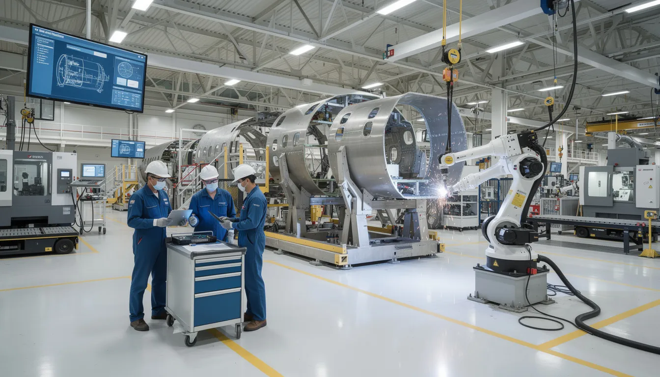
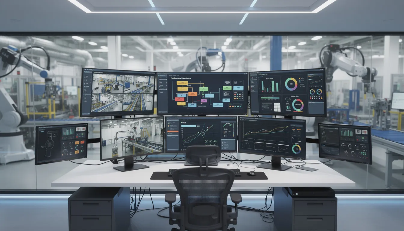
  • MES vs SCADA: Understanding Two Complementary Manufacturing Systems

    MES and SCADA are not the same system. SCADA focuses on real-time equipment monitoring, data acquisition, supervisory control, alarms, and process control. MES focuses on production execution, work coordination, quality control, traceability, production performance, and operational reporting.

    Comparing MES and SCADA systems reveals they serve different purposes in manufacturing operations. SCADA focuses on real-time equipment monitoring and control, while MES manages production execution, work coordination, quality, and traceability. Understanding these differences helps manufacturing teams choose the right systems without common implementation mistakes.

    Below is a practical comparison of MES vs SCADA capabilities and applications.

    MES vs SCADA: Key Differences

    The primary difference between MES and SCADA systems is that SCADA focuses on real-time data acquisition and process control, whereas MES manages and optimizes the entire production process.

    When integrated, SCADA provides real-time operational data while MES adds structure, context, and business logic, enabling a comprehensive view of manufacturing processes. While SCADA provides immediate insight into equipment performance and operational status, MES translates that data into actionable insights for production management and quality assurance.

    Purpose and Primary Focus

    The fundamental purpose of each system determines where they fit in manufacturing operations.

    SCADA System Purpose

    SCADA, or Supervisory Control and Data Acquisition, systems are designed to monitor and control equipment across large industrial sites, providing real-time data from machines and processes to operators.

    A SCADA system is closest to the machine and process control layer. It supports monitoring equipment, controlling machinery, collecting data from sensors, and helping operators respond quickly when industrial processes drift outside expected limits. In modern manufacturing, SCADA reads raw sensor data from Programmable Logic Controllers (PLCs) and sends alarms if a machine malfunctions.

    SCADA systems focus on:

    SCADA systems detect abnormal conditions and generate alarms to alert operators, which helps teams respond quickly to issues and minimize downtime. This makes SCADA essential when the priority is to control equipment, stabilize process control, and maintain safe production line behavior.

    MES System Purpose

    A manufacturing execution system manages what happens during production. MES software connects production orders, work instructions, quality checks, raw materials, operators, routing, and reporting into a structured operating system for the shop floor.

    MES systems are focused on managing and optimizing production execution and workflows. MES handles transactional data like order numbers, part tracking, and worker schedules. Manufacturing Execution Systems (MES) provide real-time data collection, aggregating production data from machines, operators, and systems to create a complete record of manufacturing activity.

    MES systems focus on:

    MES supports quality assurance by enforcing process rules, collecting inspection data, and maintaining full genealogy and traceability records, which is critical for regulated industries. MES enables standardized workflows and automated decision rules that reduce manual intervention and improve consistency across shifts, lines, and sites.

    Data Types and Time Horizons

    SCADA and MES systems handle different data types and operate on different time scales.

    SCADA Data and Timing

    SCADA operates in real-time, milliseconds, and seconds. It is designed for real time data capture and real time control, especially where immediate action is required to protect equipment, quality, or safety.

    SCADA systems continuously collect data from field devices and display it through Human-Machine Interfaces (HMIs), dashboards, and trends, allowing operators to quickly understand current conditions and system status.

    Typical SCADA data includes:

    SCADA data collection is especially valuable for production monitoring, alarm handling, predictive maintenance inputs, and short-cycle decision making. Historians often store this real time data so engineering teams can review trends, investigate abnormal events, and improve processes.

    MES Data and Timing

    MES operates in shifts, hours, minutes, and days. It may collect real time data from machines, operators, and systems, but its main value is adding production context to all the data coming from the factory floor.

    Typical MES data includes:

    MES connects equipment activity to the production process. For example, SCADA may know that a machine stopped at 10:14. MES can show which order was running, which operator was assigned, what part number was being built, whether raw materials were correct, whether quality control was completed, and whether the downtime reason was a breakdown, changeover, inspection hold, or missing component.

    That context supports more informed decision making. It also helps production managers optimize production, compare performance across shifts, and identify where significant improvements are possible.

    Users and Interface Design

    Each system serves different roles with distinct interface requirements.

    SCADA User Interfaces

    The user base for SCADA includes automation engineers, machine operators, and maintenance technicians. These users need fast, clear visibility into control systems and equipment conditions.

    SCADA user interfaces usually include:

    A SCADA screen is designed for immediate response. Operators need to know whether a pump is running, a valve is open, a tank is filling, a line is stopped, or a process value is outside tolerance. SCADA focuses on the current state of equipment and supports quick control actions.

    MES User Interfaces

    The user base for MES includes plant managers, supervisors, schedulers, and quality assurance inspectors. MES interfaces are designed around production workflows, quality management, and production planning rather than direct control of machinery.

    MES user interfaces usually include:

    MES helps teams coordinate the entire manufacturing process. Operators use MES to follow work instructions, record inspection results, and confirm production steps. Supervisors use MES to see bottlenecks, labor status, and line performance. Quality teams use MES to review defects, audit trails, and traceability records.

    This is why MES and SCADA answer different questions. SCADA asks, “What is the machine doing right now?” MES asks, “What are we making, how well are we making it, and can we prove it was made correctly?”

    System Integration and Architecture Layer

    Understanding where each system fits in the ISA-95 automation pyramid helps clarify their roles.

    SCADA in the Automation Stack

    SCADA sits at Layer 2, Supervisory Control, in the ISA-95 Architecture Layer. In plain terms, this means SCADA is close to equipment supervision and control.

    SCADA integrates with:

    SCADA integration often depends on industrial protocols and connectors such as OPC UA, MQTT, REST APIs, tag bridges, or digital I/O. For brownfield production plants, older control devices may require gateways before they can support seamless data flow to modern systems.

    A historian usually stores high-frequency process values, alarms, and events from SCADA. A data lake can store raw and processed data from SCADA, MES, ERP, and other systems for analytics, predictive maintenance, and digital transformation initiatives.

    MES in the Automation Stack

    MES sits at Layer 3, Manufacturing Operations Management, in the ISA-95 Architecture Layer. In plain terms, MES sits between the plant floor and enterprise resource planning.

    MES integrates with:

    ERP plans the business. MES executes the production plan. SCADA supervises equipment behavior. PLM defines the product. QMS governs quality rules. Historians and data lakes preserve data for analysis. These systems work best when they are connected without forcing every existing system to be replaced.

    Integrating MES and SCADA systems enhances operational efficiency by allowing for rapid detection of production problems and prompt decision-making, which simplifies procedures and fosters ongoing advancements within manufacturing processes. Integrating MES and SCADA systems also enhances operational efficiency by allowing for rapid detection of production problems and prompt decision-making, which supports more informed choices on the factory floor.

    The combination of SCADA and MES systems within manufacturing operations significantly improves the effectiveness of production processes, bolstering operational efficiency, diminishing wastage, and amplifying visibility throughout the stages of production. The combination of SCADA and MES systems significantly improves the effectiveness of production processes, enhancing operational efficiency, reducing waste, and amplifying visibility throughout the stages of production.

    Integrated MES and SCADA systems enable real-time surveillance and proficient control over production activities, resulting in refined plant functions with an increased capacity to adapt swiftly to modifications in production demands.

    When SCADA is Sufficient

    SCADA may be enough when the main requirement is equipment control, process visibility, and alarm response rather than production workflow coordination.

    SCADA is often sufficient for:

    For example, a utility, water treatment operation, pipeline, or stable continuous production process may prioritize process control, real time monitoring, and rapid alarm response. In these environments, the production process may not require complex routing, work instructions, serial tracking, batch traceability, or supplier documentation.

    SCADA systems can provide strong value in these cases because they support real time data acquisition, equipment visibility, remote control, and minimizing downtime. If the business does not need detailed production orders, quality records, operator task enforcement, or genealogy, a SCADA system and historian may cover most operational requirements.

    However, SCADA alone becomes limited when leaders need to connect equipment data to order context, production planning, quality management, and compliance records.

    When MES is Essential

    MES is essential when manufacturing operations need more than equipment-level visibility. If the business must coordinate people, materials, work instructions, quality checks, routing, and documentation, MES software becomes the execution layer.

    MES is usually needed for:

    This is common in aerospace, defense, medical device, electronics, automotive, and other regulated or high-mix manufacturing processes. In these environments, knowing that a machine ran is not enough. Teams need to know which part was produced, which serial number was installed, which operator completed the step, which inspection result passed, which revision of the work instruction was used, and whether the full record is audit-ready.

    MES supports consistent product quality by enforcing process rules and capturing production data as work happens. It also supports operational efficiency by reducing manual intervention, replacing paper travelers, improving data collection, and helping production managers identify scrap, rework, bottlenecks, and downtime causes.

    For regulated industries, MES is often the difference between having production data and having defensible production records.

    When Both Systems are Needed

    Many manufacturers need both SCADA and MES because the two systems solve different parts of the operational problem.

    Both are often needed in:

    In an integrated model, SCADA provides real time data from equipment and control systems. MES adds production context, quality rules, workflow logic, and traceability. Together, SCADA and MES create a seamless integration between the factory floor and higher level systems.

    For example, SCADA may detect that a production line has slowed. MES can connect that event to the production order, shift, operator, routing step, material lot, and quality status. ERP can then receive accurate updates about production progress, inventory movement, and delivery risk.

    This connected approach improves overall operational efficiency because leaders can move from production monitoring to action. Engineering teams can investigate equipment behavior. Quality teams can review inspection data. Production managers can make schedule decisions. Digital transformation teams can create a reliable data foundation for predictive maintenance, analytics, and continuous improvement.

    When a Lighter Operations Layer Makes Sense

    A full MES is not always the most practical first step. Some aerospace and MRO organizations need execution workflows, traceability, quality checks, supplier visibility, and reporting, but they cannot afford a heavy rip-and-replace implementation.

    A lighter operations layer makes sense for:

    This is where Connect 981 fits. Connect 981 should not be treated as a SCADA replacement. It does not replace real time control, supervisory control, or machine safety functions. It is also not a claim to replace every MES in every environment.

    Connect 981 is better understood as a practical operations layer for aerospace and MRO teams. It helps connect shop floor execution, work instructions, quality checks, traceability, supplier data, and reporting without forcing every existing system to be removed.

    For teams with ERP, PLM, QMS, SCADA, or legacy systems already in place, Connect 981 can support the missing execution layer: the place where operators complete work, inspectors capture quality data, suppliers share documentation, and leaders see production performance. This is especially useful when full MES deployment would be too slow, too costly, or too disruptive.

    Common Implementation Mistakes

    The biggest mistake is treating MES and SCADA as interchangeable systems. They are complementary, but they should not be forced into each other’s role.

    Common mistakes include:

    SCADA is not designed to manage operator workflows, quality forms, batch records, genealogy, or compliance documentation. Trying to make SCADA do those jobs often creates manual workarounds and weak traceability.

    MES is not designed to control machinery in milliseconds. Expecting MES to perform real time control or machine safety functions creates risk because process control belongs in PLCs, DCS, and SCADA systems.

    ERP disconnection is another common issue. If enterprise resource planning sends production orders to the plant but does not receive accurate updates from the shop floor, production planning becomes unreliable. Teams then build spreadsheet bridges, manual reports, and email-based status updates. Those workarounds are fragile, slow, and difficult to audit.

    A better approach is to define the role of each system clearly: SCADA for equipment supervision and control, MES for production execution and workflow management, ERP for enterprise planning, PLM for engineering data, QMS for quality governance, historians for process data, and data lakes for broader analytics.

    MES vs SCADA: Choosing the Right Approach

    Choose SCADA when equipment control, real time monitoring, process visualization, alarm response, and data acquisition are the primary needs.

    Choose MES when production execution, work instructions, quality tracking, traceability, production orders, downtime analysis, and workflow management are essential.

    Choose integrated MES and SCADA systems when manufacturing operations need both equipment-level visibility and production-level context. This is the right direction for comprehensive manufacturing operations, regulated production, complex production lines, and digital transformation programs that require complete operational visibility.

    Choose a lighter operations layer when a full MES is too heavy, but the business still needs structured execution workflows, quality checks, supplier visibility, batch traceability, and reporting. For aerospace and MRO teams, Connect 981 provides a practical way to connect shop floor execution, quality, supplier data, and compliance workflows without replacing every existing system.

    The best decision is rarely “MES vs SCADA” as competitors. The better question is: which layer is missing from your industrial automation stack?

    If your team needs to connect shopfloor execution, quality records, supplier workflows, and compliance reporting without ripping out SCADA, ERP, PLM, QMS, or other existing systems, request a demo to see how Connect 981 works in action.

  • Aerospace Manufacturing Operations: Executive Guide for Modern Programs

    Aerospace Manufacturing Operations: Executive Guide for Modern Programs

    The aerospace industry in 2025 and 2026 faces a straightforward reality: backlogs are growing, fleets are aging, and the operational approaches that worked a decade ago cannot deliver the throughput required today. COOs and plant leaders must answer a practical question over the next 12 to 24 months. What should we actually do differently in our operations?

    Aerospace manufacturing operations represent the integrated system where precision engineering meets rigorous production standards. This encompasses concept design through industrialization, sourcing raw materials like titanium alloys and ceramic matrix composites, high-volume production via CNC machining and additive manufacturing, final assembly with automated systems, extensive testing, certification under AS9100 and FAA frameworks, delivery to OEMs, and ongoing aftermarket MRO involving disassembly, inspection, repair, and recertification.

    This executive guide connects ERP, MES, quality systems, workforce management, and digital execution strategies into a coherent operational framework. The perspective comes from Connect981, a B2B SaaS platform built specifically for aerospace manufacturing and MRO realities rather than generic discrete manufacturing.

    The image depicts a busy aerospace factory floor, showcasing precision machinery and workers engaged in the aerospace manufacturing process within a controlled environment. This setting highlights advanced manufacturing technologies and emphasizes the importance of safety and performance standards in the aerospace industry.

    The State of Aerospace Manufacturing and MRO in 2025–2026

    The global aerospace parts manufacturing market stood at approximately $930 billion in 2024, projected to reach $1.2 trillion by 2034 with a CAGR of 3.8%. North America continues to dominate due to its mature ecosystem, defense contracts, and leadership in advanced manufacturing technologies including digital twins and AI-powered quality control.

    Key demand drivers shaping aerospace operations include:

    • Commercial aviation recovery with Airbus holding 8,617 outstanding orders and Boeing at 6,528 as of May 2025, translating to roughly 5,000 undelivered aircraft
    • Defense modernization accelerating hypersonics, UAVs, and autonomous systems requiring high production rates
    • Commercial space expansion via reusable launch vehicles and satellite constellations
    • Fleet aging to 11.3 years from 9.7 in 2018, with airlines extending leases 11% more in 2024 versus 2018

    Operational realities include chronic supply chain instability with 12 to 24 month lead times for titanium alloys, semiconductor shortages, and labor constraints with over 60% of aerospace manufacturers citing workforce issues. Certification timelines stretch 6 to 12 months for simple parts and up to 7 years for complex systems such as engines or airframes.

    MRO growth has become a strategic focus area. Engine scarcity crises are reshaping aftermarket economics, with new capacity expansions emerging in Middle East and Asia hubs to address turnaround time pressures.

    Core Building Blocks of Aerospace Manufacturing Operations

    The aerospace manufacturing process follows an end-to-end value chain:

    • Concept design in PLM systems managing configurations and BOMs
    • Industrialization creating build books and route cards
    • Sourcing with approved vendor lists tracking heat lots and batches
    • Production via shopfloor execution with travelers and digital work instructions
    • Final assembly and test incorporating NDT signoffs and torque verifications
    • Certification via AS9102 FAIs and AS9145/APQP processes
    • Delivery and ongoing aftermarket MRO

    The main operational domains include:

    Domain

    Key Activities

    Artifacts

    Engineering and Industrialization

    ECO management, configuration control

    Build books, route cards

    Shopfloor Execution

    WIP tracking, operation sequencing

    Travelers, work instructions

    Quality and Compliance

    CAPA workflows, audit trails

    FAIRs, nonconformance records

    Supply Chain Management

    Supplier OTD, PPM monitoring

    Approved vendor lists, POs

    MRO Operations

    Dynamic routing, findings management

    Task cards, SB/AD compliance logs

    The typical system landscape features ERP for finance and inventory, PLM for design revisions, MES for machine scheduling and OEE, and QMS for nonconformance and audits. Gaps persist in operator guidance, rich routing logic, and cross-system unification. A digital operations layer like Connect981 emerges as the connective tissue, aggregating data without replacing core systems.

    Operational Visibility for Aerospace Leaders

    COOs and plant managers need real-time visibility across programs, sites, and suppliers to monitor WIP status, bottlenecks, quality escapes, and MRO turnaround times. Current visibility gaps typically manifest as weekly slide decks, manual status spreadsheets, email updates from suppliers, and poor cross-site comparability.

    Modern operational visibility means unified dashboards pulling from ERP, MES, QMS, and execution systems into a single pane of glass. Role-based views allow plant managers to see site performance while program leaders track cross-factory progress.

    KPIs aerospace executives should see at a glance:

    • OTD by program targeting 95%+ for tier-1 suppliers
    • First-pass yield typically 85-95% in precision machining
    • Rework rate ideally under 5%
    • Hours per unit by operation
    • TAT by MRO routing with 30-60 day targets for engine shops
    • AS9100 and FAA audit findings trends
    • Supplier delivery and quality performance metrics

    Connect981 acts as that visibility layer by aggregating work order execution data, digital work instructions status, and supplier workflow milestones into live reports. Site comparison views allow leaders to identify which facilities execute similar operations faster and why.

    The image depicts a modern manufacturing control room featuring multiple digital dashboards that showcase real-time production data essential for optimizing aerospace manufacturing processes. This high-tech environment highlights the integration of advanced manufacturing technologies to enhance operational efficiency and ensure compliance with safety and performance standards.

    Scaling Aerospace Programs Without Losing Control

    Ramping a new aircraft, engine, or subsystem program from prototype to LRIP and then to full-rate production presents specific challenges between 2025 and 2030. Commercial aerospace sector OEM ambitions frequently outpace supply chain capacity, while defense industry rapid capability deployment demands accelerated timelines.

    Pain points during scale-up include:

    • Configuration proliferation from engineering change orders
    • Late-breaking engineering changes disrupting production schedules
    • Incomplete build documentation causing rework
    • Inconsistent processes across plants and suppliers amid backlogs

    Standardized digital work packages address these challenges. Routing, work instructions, inspection plans, torque charts, and test steps can synchronize multiple lines via template-based workflows and controlled revision releases. Automated alerts flag when work starts on superseded revisions.

    Scalable operations require governance around AS9100, AS9102 FAI, AS9145/APQP, and NADCAP processes built into daily execution rather than living only in manuals. Complex geometries requiring hybrid additive-traditional manufacturing methods demand consistent documentation across facilities.

    A digital execution layer like Connect981 supports consistent rollouts across multiple factories and suppliers without forcing a full MES overhaul. Templates propagate instantly, and revision control ensures every site works from current documentation.

    Workforce Productivity and the Aerospace Skills Gap

    The aerospace sector faces a skills challenge with high retirement rates among experienced mechanics and machinists combined with difficulty attracting younger talent into complex, regulated environments. Over 60% of aerospace manufacturers cite workforce issues as a primary constraint, with UK manufacturers reshoring over 50% of production to mitigate risks.

    Typical productivity drains include:

    • Searching for the correct revision of work instructions
    • Walking to paper binders for reference documents
    • Re-entering data from travelers into systems
    • Manual article inspection documentation for FAIRs

    Digital work instructions with embedded photos, 3D models, torque charts, and checklists shorten onboarding time by 30-50% and reduce dependency on tribal knowledge. A technician drilling composite panels or assembling wiring harnesses can follow visual guidance rather than interpreting text-heavy procedures.

    AI assistance in platforms like Connect981 guides technicians through root cause analysis, suggests likely causes of recurring defects, and flags missing quality steps. Before digitization, paper-based operations typically take 20-30% longer per unit than digitized flows that capture timestamps and parameters automatically.

    An aerospace technician is focused on a tablet device while working on an aircraft component, highlighting the integration of digital tools in the aerospace manufacturing process. This scene emphasizes the importance of technology in optimizing production processes and ensuring quality control in the aerospace industry.

    Digital Execution Layers vs. Traditional MES and ERP

    Understanding the difference between core transaction systems, heavy MES layers, and modern lightweight digital execution platforms clarifies where gaps exist.

    ERPs handle orders, finance, and inventory well but fall short on operator guidance, in-process quality checks, and detailed traceability at the operation level. Traditional MES manages machine scheduling, OEE, and automation interfaces but gaps appear in documentation control, rich routing logic, supplier collaboration, and MRO workflows.

    A digital operations layer sits above and between ERP, MES, PLM, and QMS. It coordinates work instructions, checklists, approvals, and contextual data for each task without requiring system replacement.

    Concrete integration patterns include:

    • Pulling work order and BOM data from SAP or Oracle
    • Associating production tasks with CAD/PLM revisions
    • Pushing completion data and nonconformance records back into ERP/QMS
    • Faster ECN propagation across connected systems

    Executives do not need to rip-and-replace existing systems to achieve modern execution capabilities. Connect981 extends the existing landscape rather than competing with established infrastructure investments.

    Quality, Traceability, and Compliance by Design

    Aerospace and MRO operations require designing in quality and traceability from day one to satisfy safety and performance standards under AS9100, AS9102, NADCAP, ITAR, FAA, EASA, and OEM customer certification requirements.

    Concrete practices include:

    • Serial and batch number traceability throughout production processes
    • Heat lot control for specialty alloys and key components
    • Digital FAIRs replacing paper-based first article inspection
    • CAPA workflows with immutable audit trails
    • Sign-off records for every process change and rework event

    Digital work instructions embed mandatory quality checkpoints that must be completed before advancing operations. Torque verification, NDT signoff, and visual inspections gate progression automatically rather than relying on technician memory.

    The value during audits becomes clear: instant access to routing, parameters, technicians, calibrated tools, and rework history for any serial number. Regulatory bodies and OEM quality representatives can verify compliance without manual document retrieval.

    Connect981 captures these elements automatically as technicians execute work, reducing reliance on manual forms and scanned PDFs. Quality escapes drop 20-40% in certified environments using embedded checkpoint enforcement.

    Connected Factory: Integrating ERP, MES, PLM, QMS, and Supplier Systems

    The typical aerospace IT landscape in 2025 includes multiple ERPs across regions, legacy MES installations, PLM for design, standalone QMS, and supplier portals. These systems remain only partially integrated.

    Data silos create issues:

    • Mismatched revisions between PLM and shopfloor instructions
    • Delayed quality feedback to engineering teams
    • Limited supplier visibility into engineering or routing changes
    • Configuration drift between production sites

    A unified operations layer reads and writes to these complex systems, ensuring technicians, engineers, and supplier partners all see the same current configuration. Technology integration patterns include API-based connections for modern systems and file-based exchanges where legacy infrastructure requires it.

    Role-based data sharing respects international traffic in arms regulations and export controls while enabling necessary collaboration. Connect981 bridges OEM and tier-1 systems with tier-2 and tier-3 suppliers, enabling shared workflows for build packages, FAIR approvals, and deviation management.

    Business outcomes include fewer build holds, faster engineering change implementation, and reduced rework from revision mismatches.

    Managing Complex Aerospace Supply Chains

    Aerospace supply chains remain fragile due to long lead times for titanium and specialty alloys spanning 12 to 24 months, semiconductor constraints, complex electronics, and thousands of tier-2 and tier-3 suppliers per program. Supply chain resilience has become a board-level priority.

    Geopolitical events, export controls under ITAR and EAR, and evolving cybersecurity requirements under CMMC add layers of operational risk. The defense systems segment faces particularly stringent requirements affecting prime contractors and their supplier networks.

    Operational impacts include:

    • Line-stopping shortages requiring production schedule changes
    • Out-of-sequence work creating downstream complications
    • Expedited freight costs eroding margins
    • Last-minute engineering deviations to accommodate substitute parts

    Digital supply chain coordination addresses these challenges through shared build packages, real-time PO and routing visibility, and supplier progress updates integrated directly into factory execution views. Aerospace customers gain transparency into supplier status without manual status calls.

    Connect981 supports supplier collaboration by giving external partners controlled access to relevant work instructions, quality requirements, and documentation checklists. Coordinating FAIRs, managing approved vendor lists, and monitoring supplier on-time delivery and PPM become streamlined activities rather than administrative burdens.

    Aerospace MRO Operations and Turnaround Time Optimization

    Aerospace MRO differs fundamentally from new production through variable work scopes, discovery-driven routing, and heavy dependence on historic maintenance records. Predictive maintenance strategies intersect with traditional scheduled overhaul requirements.

    Key MRO metrics include:

    Metric

    Target

    Impact

    Turnaround time (TAT)

    30-60 days for engine shops

    Customer satisfaction, lease costs

    On-time release

    95%+

    Contract compliance

    Findings-per-visit

    Trending analysis

    Process optimization

    Rework rate

    Under 5%

    Cost control

    Repeat visits within 18-24 months

    Minimized

    Quality verification

    Digital routing and task cards adapt dynamically during disassembly and inspection, updating work content as findings are logged. An engine module strip reveals conditions that modify the repair scope in real time rather than requiring separate paper processes.

    Integrated parts traceability and maintenance history improve decisions on repair versus replace and help prove compliance to regulatory requirements and lessors. Connect981 unifies MRO planning, routing execution, parts kitting, quality checks, and customer approvals in one view, reducing TAT by 15-25% and eliminating paperwork cycles.

    The image depicts an aircraft engine being meticulously inspected during maintenance at a modern MRO facility, highlighting the critical aerospace manufacturing processes that ensure safety and performance standards in the aerospace industry. Skilled technicians are seen utilizing advanced manufacturing technologies and quality control measures to optimize production processes and maintain the reliability of aerospace components.

    Leveraging AI and Analytics in Aerospace Manufacturing Operations

    Realistic AI and data analytics use cases achievable on the factory floor before 2028 focus on operational improvement rather than speculative autonomous systems. Machine learning applications must meet aerospace constraints around certification requirements and model validation expectations.

    Specific opportunities include:

    • Predictive quality flagging likely nonconforming operations before completion
    • Anomaly detection in process control data
    • Intelligent routing suggestions based on historical performance
    • AI-assisted root cause analysis for CAPA workflows
    • Real time feedback on process deviations

    Operational data collected in Connect981 including timestamps, user actions, defect types, and process parameters feeds these models to deliver program-specific insights. Advanced analytics reveal patterns invisible in manual review.

    Constraints unique to aerospace demand explainable AI for regulators and internal quality authorities. Aerospace companies must govern AI adoption through phased pilots on selected lines or MRO cells, human-in-the-loop decision making, and clear boundaries between advisory and automated actions.

    Examples include reducing scrap on composite layup by 10-20% or improving FAI pass rates on complex machined specialized components through pattern recognition.

    Implementation Roadmap: From Paper and Spreadsheets to a Connected Operations Layer

    A pragmatic 12 to 24 month transformation roadmap for aerospace plants reliant on paper travelers, spreadsheets, and shared drives follows a phased approach to optimize production processes.

    Months 1-6: Foundation

    • Select one value stream or MRO cell for initial digitization
    • Digitize work instructions and quality checklists for repetitive tasks
    • Establish baseline metrics for comparison
    • Train core team on platform capabilities

    Months 6-12: Expansion

    • Expand to quality workflows and parts traceability
    • Connect supplier collaboration for selected programs
    • Integrate with ERP for work order data synchronization
    • Measure first-pass yield improvements and reduce waste

    Months 12-24: Enterprise Scale

    • Roll out across additional production lines and sites
    • Standardize workflows based on lessons learned
    • Enable cross-site visibility and benchmarking
    • Extend to MRO operations and additional supplier tiers

    Cross-functional governance requires operations, manufacturing engineering, quality, IT, and supply chain jointly defining standard workflows and data structures. Aviation management leadership must champion adoption.

    Connect981’s zero and low-code platform shortens deployment using aerospace-specific templates for FAI, inspection, routing, and concessions. Early wins like reducing missing paperwork by 50% or shortening signoff cycles build organizational momentum and support continuous improvement.

    How Connect981 Supports Modern Aerospace Manufacturing Operations

    Connect981 serves as a unified aerospace operations platform connecting ERP, MES, PLM, QMS, and supplier systems into one digital execution layer. The platform addresses aerospace and defense industry requirements rather than generic industrial manufacturing needs.

    Core capabilities mapped to operational priorities:

    • Digital work instructions with embedded media and version control
    • Shopfloor execution tracking with real-time WIP visibility
    • Serial and lot traceability throughout production cycles
    • Integrated quality workflows with checkpoint enforcement
    • Supplier collaboration with controlled access and shared documentation
    • MRO routing management with dynamic task adaptation

    Scenario examples:

    • Ramping a new program across multiple sites with consistent work packages and synchronized documentation releases
    • Stabilizing a critical supplier through shared FAI workflows and deviation management
    • Reducing TAT in an engine MRO shop by 20% through unified planning and execution views

    Connect981 differentiates from general MES and low-code platforms through aerospace-first data models, templates for AS9100 and FAA workflows, and fast time-to-value without requiring system replacement. Digital tools deploy in weeks rather than months.

    Conclusion: Next Steps for Aerospace Operations Leaders

    Modern aerospace manufacturing operations require integrated visibility, scalable processes, empowered workforces, and a digital execution layer bridging legacy systems. The aerospace projects demanding attention in 2026 cannot wait for multi-year transformation programs.

    Executive priorities for the next 18 to 24 months:

    1. Unify operational data across ERP, MES, and shopfloor systems
    2. Digitize work instructions and quality flows to reduce cost and development cycles
    3. Standardize processes across sites using template-based workflows
    4. Connect suppliers and MRO operations into shared visibility frameworks

    Leaders can assess current maturity by inventorying paper-based workflows, counting manual spreadsheets used for production control, and reviewing audit findings related to documentation and traceability. The biggest challenges often hide in plain sight.

    A pilot with Connect981 on a targeted program or MRO cell provides a low-risk path to validate benefits and balance innovation with operational continuity. Strategic partnerships between operations leadership and digital platforms enable aerospace companies to stay competitive. Educational institutions and leadership programs increasingly emphasize digital manufacturing competencies for future workforce development.

    The next 18 to 24 months will separate organizations that digitize execution from those still managing paper trails. Operational efficiency gains compound across programs when the foundation is right. Request a Demo to see how Connect981 extends your existing ERP and MES landscape to meet aerospace production demands and ensure safety across other industries and beyond.