RSC Cluster: Aerospace MES, Inventory Accuracy, and AOG Risk Reduction

  • Why is inventory accuracy harder in aerospace than in other industries?

    Unique characteristics of aerospace inventory

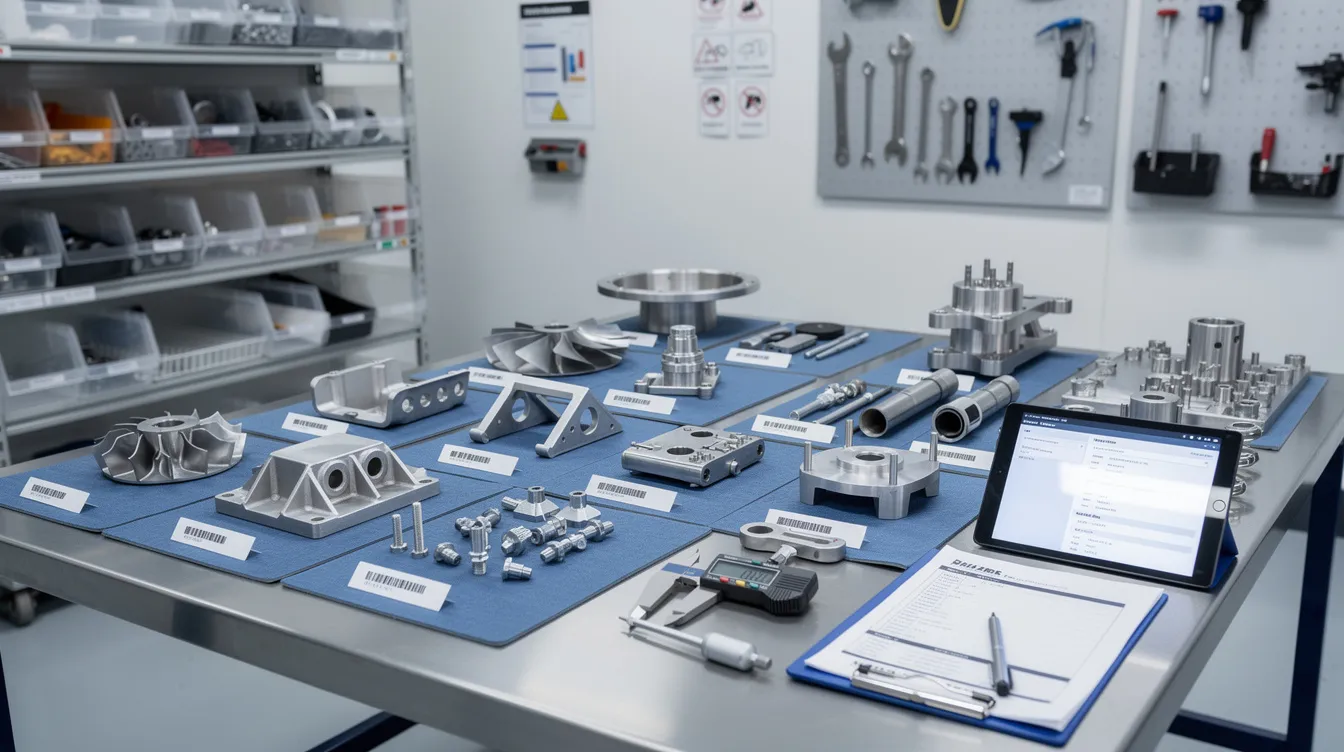
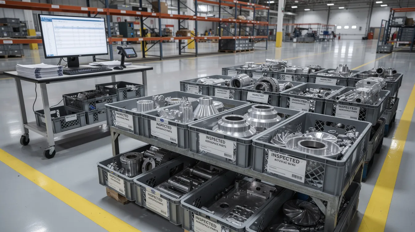
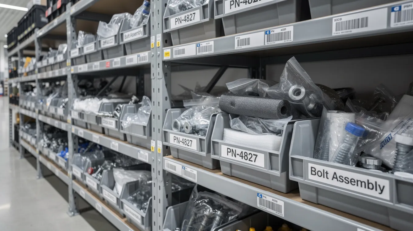
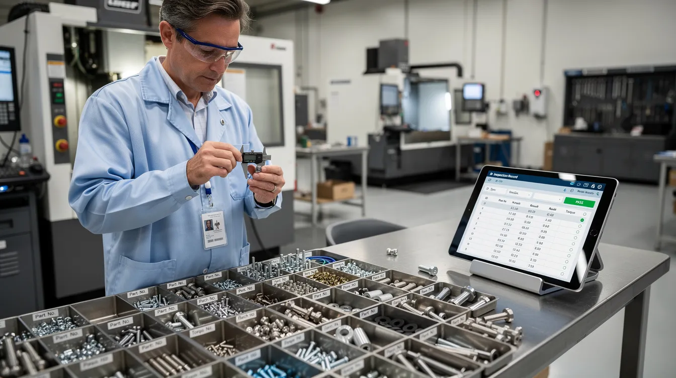
    Inventory accuracy is harder in aerospace because the items being tracked are high value, safety critical, and subject to strict traceability requirements. Instead of tracking pallets of identical parts, you are often tracking individual serial numbers, heat lots, and configuration states. A single line item in the ERP can represent many units, each with different certifications, storage conditions, or applicability limits. This turns what is a basic quantity problem in other industries into a combined quantity, identity, and pedigree problem in aerospace.

    Aerospace bills of material typically include complex alternates, effectivity ranges, and life limits, so “having the right part” is not as simple as matching a part number. Two items with the same part number may not be substitutable due to different revisions, suppliers, or approvals. That makes inventory accuracy not just about count, but about whether each stock-keeping unit can actually be used on a given assembly or aircraft.

    Serialization, traceability, and paperwork load

    Many aerospace parts are serialized or at least lot-controlled, and those identifiers must remain traceable from supplier through manufacturing, test, and in-service. Each movement of a serialized part should update multiple systems: ERP/MRP, MES, QMS, and sometimes separate serialization or repair tracking tools. When these systems are loosely integrated, every transfer becomes a chance for misalignment between physical inventory and records.

    Paper-based processes and disconnected scanners are still common because of validation burden and certification constraints, especially around controlled documents. Travelers, certificates of conformity, and inspection records often move with the parts and are keyed in later, if at all. Delays and manual entry errors in this paperwork create timing gaps where inventory exists physically but not yet digitally, or vice versa. Over time, these small mismatches compound into larger inventory accuracy issues.

    Regulatory and quality constraints that limit simplification

    In less regulated industries, teams can streamline inventory practices, consolidate SKUs, or relax controls to reduce complexity. Aerospace manufacturers often cannot do this without triggering requalification, regulatory review, or customer approval processes. Labeling, storage, and handling rules are constrained by specifications and contracts, which can prevent seemingly simple fixes like re-binning materials or changing how parts are grouped.

    Quality and airworthiness requirements also discourage aggressive cycle-count or rework practices that would otherwise clean up data. For example, scrapping or re-identifying ambiguous inventory may require formal material review boards and extensive documentation. This slows down correction of obvious errors and increases the temptation for local workarounds that bypass formal inventory adjustments.

    Engineering change and configuration complexity

    Engineering change is a major driver of inventory complexity in aerospace. Design updates, service bulletins, and customer-specific configurations all shift which inventory is usable, where, and under what conditions. Parts that were fully usable last month may become limited to certain configurations or require rework before use. If configuration rules in the ERP/MES do not keep pace with engineering changes, the same physical inventory can be represented very differently in different systems.

    Configuration-managed products also mean that a single finished item (an engine, avionics unit, or structure) can exist in multiple approved configurations across a long service life. Subcomponents may be swapped, repaired, or upgraded many times, and each of these events changes the effective inventory and its pedigree. Maintaining accurate inventory across new-build, spare parts, and repair/overhaul flows requires discipline that is harder to sustain than in simpler, once-and-done product lifecycles.

    Brownfield system landscapes and integration debt

    Most aerospace plants operate with a patchwork of legacy ERP, MES, PLM, and QMS systems that have grown over decades. These systems may encode different units of measure, location hierarchies, or part numbering schemes, making consistent inventory representation difficult. When inventory moves across organizational or system boundaries (e.g., from a repair shop to final assembly), reconciliation often relies on spreadsheets, email, or manual uploads.

    Replacing these systems wholesale is rarely practical due to validation cost, change-control overhead, and downtime risk. As a result, inventory accuracy improvements must coexist with existing tools and interfaces, which can limit how far you can automate or centralize. Point-to-point integrations and tactical fixes accumulate over time, introducing subtle mismatches in how quantity, status, and location are tracked. These structural constraints mean that even well-designed process improvements may not fully eliminate discrepancies.

    Complex storage rules, shelf life, and special handling

    Aerospace materials often include chemicals, composites, and life-limited components that require specific storage conditions and strict shelf life control. Inventory records must capture not just how much you have, but remaining life, exposure history, and storage conditions. When these attributes are tracked in separate systems or on local logs, it becomes easy for the main inventory record to fall out of sync with reality.

    Kitting and staging add another layer of complexity. Parts are frequently pulled from bulk storage into kits for specific orders or aircraft tails, then partially returned, scrapped, or reassigned. If the kitting and de-kitting processes are not tightly controlled and systemized, inventory tends to fragment into locations and statuses that are opaque to the main ERP. This is fundamentally different from simpler, one-way flows commonly seen in high-volume consumer manufacturing.

    Human factors and local workarounds

    Because of schedule pressure and the cost of line stoppages, operators and planners in aerospace will often solve local problems first and update systems later, if at all. This might mean borrowing parts across work orders, reassigning serials, or holding material in informal buffer locations. These behaviors are understandable in context but directly undermine formal inventory accuracy.

    The training burden is also higher: staff must understand not only how to move parts but also the implications for serial tracking, configuration, and certification. When processes are complex, system usability is poor, and feedback cycles are slow, people rationally prioritize getting hardware built over perfect record-keeping. Over years, these small, rational decisions create systemic inventory issues that are much harder to unwind than simple counting mistakes.

    What this means for improving inventory accuracy in aerospace

    Improving inventory accuracy in aerospace typically requires addressing both data and process, within the constraints of existing validated systems. Efforts that work well in other industries—such as rapid system replacement, SKU simplification, or aggressive re-labeling—often run into qualification, certification, and downtime barriers. Instead, gains tend to come from targeted integration, better event capture at the point of work, and incremental tightening of kitting, returns, and scrap processes.

    Expect diminishing returns: moving from poor to acceptable accuracy is feasible with disciplined basics, but achieving near-perfect accuracy is difficult when serialization, configuration, and long lifecycles are involved. Any initiative should explicitly account for brownfield reality, multi-system alignment, and the need to adjust human behaviors that have grown around the current constraints. Without that, projects risk becoming one-time inventory cleanups rather than sustained improvements.

  • Can MES alerts integrate with existing incident or ticketing tools?

    Short answer and key constraints

    Yes, MES alerts can integrate with existing incident or ticketing tools in most environments, but it is not automatic and not risk‑free. The feasibility and value depend on your MES’s integration capabilities, the APIs or connectors exposed by your ticketing system, and how tightly controlled your validated landscape is. In regulated operations, you should assume configuration, custom integration work, and formal validation will be required before using this for regulated or quality‑relevant events. Integration is usually most successful when it augments existing workflows instead of trying to completely replace them on day one.

    Typical integration patterns

    Common approaches include event‑based APIs, where MES publishes alerts via REST, message queues, or webhooks that create tickets in tools like ServiceNow, Jira, or ITSM platforms. Another approach is middleware or ESB integration, where a central integration layer maps MES events into standardized incident formats, often already used by IT or maintenance teams. Some MES vendors ship pre‑built connectors, but these still need configuration, data mapping, and testing to reflect your codes, asset hierarchy, and severity logic. In more constrained or older environments, CSV or database‑level exports may be used, but those are harder to validate and control, and often only suitable for non‑critical data flows.

    What can realistically be automated

    In most plants, you can automate the basic creation and enrichment of tickets from MES alerts, including the equipment, time, shift, product, and key context fields. You can often route different types of alerts to different queues (e.g., IT service desk for system issues, maintenance CMMS for equipment downtime, quality for nonconformances). Automatic status synchronization (e.g., ticket closed → MES alert acknowledged or vice versa) is possible but more complex and needs careful design to avoid conflicting states. Full closed‑loop automation, where all escalation rules and approvals are driven entirely by MES and ticketing tools, is much harder to validate and maintain and is usually only achieved after several iterations.

    Brownfield and coexistence with existing systems

    In brownfield environments, MES is usually just one of several event sources feeding incident and ticketing tools, alongside SCADA, historians, CMMS, and IT monitoring. Trying to make MES the single source of truth for all incidents typically fails, because other systems already own critical parts of the workflow (e.g., maintenance approvals or IT change management). A more workable pattern is to let MES generate specific classes of tickets (for example, production‑related events, batch deviations, or recipe download failures) while leaving existing flows intact for IT and facilities. Over time, you can adjust routing and classification rules as you gain confidence in data quality and response behavior.

    Regulated environment and validation implications

    Once MES‑driven tickets are used to manage quality‑impacting events, deviations, CAPAs, or batch record issues, the integration itself becomes part of the validated landscape. This means change control, documented requirements, risk assessment, configuration specs, test evidence, and impact analysis on upgrades. Any logic that routes or suppresses alerts, or that automatically creates or closes tickets, needs to be traceable and testable. Vendors’ out‑of‑the‑box connectors help, but their configuration and your mappings still need validation; a generic claim of “certified” integration does not remove that burden. Plants with heavy qualification requirements often limit automation to well‑understood use cases and keep manual checks or approvals for high‑risk events.

    Failure modes and tradeoffs

    Common failures include alert storms creating hundreds of low‑value tickets, which leads operators and support teams to ignore them. Misconfigured mappings can route production‑critical issues to the wrong queue or priority, delaying response. Poorly synchronized state logic can leave MES showing an “open” alert while the ticketing system shows “resolved,” undermining trust in both. A tightly coupled integration may also make upgrades painful: changes to MES alert types or ticketing fields can break the integration and require revalidation. The tradeoff is between automation and flexibility: more automation can reduce response time and manual data entry but increases complexity, validation overhead, and long‑term maintenance.

    Why full workflow replacement usually fails

    Attempts to replace existing incident or deviation workflows completely with an MES–ticketing integration often run into qualification and change‑management barriers. Maintenance and IT systems are frequently entrenched, validated, and deeply integrated with spare parts, vendor contracts, and configuration management databases. Fully rerouting those processes through MES alerts can require extended downtime, cross‑system requalification, and retraining of multiple departments. Integrations also have to respect long equipment lifecycles; you may have machines that cannot emit the data needed for fine‑grained MES alerts, limiting how far you can push end‑to‑end automation. In practice, incremental integration targeting a few high‑value alert categories is more sustainable than a big‑bang replacement.

    Connecting this to your environment

    If you already use an incident or ticketing platform for IT or maintenance, treat MES as an additional event source, not a new incident system. Start by defining which MES alerts truly warrant automatic tickets and which should remain as on‑screen notifications or reports. Validate that the required data elements (equipment ID, batch, product, severity) are consistently available and mappable into the ticketing tool’s fields. Plan for a pilot with limited scope, instrument the pilot for false positives and response times, and feed that back into alert logic and routing rules. Only after the integration behaves predictably should you consider using it for quality‑relevant incidents or deviations under full change control and validation.

  • Serialized Component

    Core meaning

    A **serialized component** is a manufactured part or assembly that is given a **unique serial number** and is tracked individually throughout its lifecycle. This serial number acts as a persistent identifier that distinguishes one physical item from all others, even if they are the same model or batch.

    Serialized components are common in regulated, high-value, or safety‑critical products, where individual history, usage, and status must be traceable over time.

    Characteristics in industrial operations

    In manufacturing and industrial operations, a serialized component typically:

    – Has a **unique serial identifier** (e.g., laser-marked on the part, on a label, or in embedded memory such as RFID).
    – Is recorded in one or more systems (e.g., MES, ERP, PLM, CMMS, QMS) under that serial number.
    – Carries its **genealogy and history**, such as:
    – Production orders and work centers where it was built
    – Material lots/batches used in its manufacture
    – Test, inspection, and calibration results
    – Repairs, rework, and maintenance events
    – Installation and removal from higher-level assemblies or equipment
    – May be subject to **configuration control**, where specific versions or revisions are tied to a given serial number.

    Serialized components can be:

    – **End items** (finished products shipped to customers)
    – **Subassemblies** inside larger systems (e.g., a serialized PCB within a medical device)
    – **Spare parts** tracked individually for field service or maintenance

    Serialization vs. other identification schemes

    A serialized component is distinct from other identification types:

    – **Serialized component**
    – Identified by a **unique serial number per physical item**.
    – Enables tracking of each individual unit’s history and status.
    – **Lot- or batch-tracked component**
    – Identified by a **lot or batch number** shared by many items.
    – Tracks the group’s history, not each individual piece.
    – **Non-tracked or generic component**
    – Identified only by part number or SKU.
    – No persistent link to the individual physical item.

    In many plants, the same part number can be:

    – Serialized in some contexts (e.g., for certain customers, regions, or regulations), and
    – Only lot-tracked or not tracked individually in others.

    Use in digital systems and workflows

    Serialized components play a central role in digital manufacturing and operations systems:

    – **MES (Manufacturing Execution System)**
    – Captures serial numbers at key production steps.
    – Associates process parameters, operator actions, and test results with each serial.
    – **ERP and inventory systems**
    – Track serialized stock movements, shipping, and returns at the serial level.
    – Support warranty and entitlement lookups by serial number.
    – **QMS and deviation systems**
    – Link nonconformances, concessions, and corrective actions to specific serials.
    – Enable focused recalls or containment actions by list of affected serial numbers.
    – **Maintenance and asset management (CMMS/EAM)**
    – Treat certain serialized components as maintainable assets (e.g., pumps, drives, modules).
    – Store service history, operating hours, and condition data by serial.

    In OT/IT integration scenarios, serialized component identifiers may be scanned, read from machine controllers, or retrieved via integration with automation systems to ensure accurate, real-time traceability.

    Common confusion and boundary clarification

    – **Serialized component vs. serial number**
    The *serial number* is the identifier; the *serialized component* is the physical item that carries it. Systems often use the term “serial” or “S/N” as shorthand, but conceptually the component and its identifier are distinct.

    – **Serialized component vs. equipment asset**
    A serialized component can be treated as an asset, but not all serialized components are managed as full equipment assets in maintenance systems. For example, a disposable serialized sensor may be fully traceable but never maintained.

    – **Serialized software components**
    In IT or software licensing, “serialized component” can also refer to software modules tied to a license key or digital serial. On this site, the term primarily refers to **physical manufactured components**, though software identifiers may be linked to their hardware serials.

    Site context application

    Within manufacturing and regulated operations, serialized components are a foundation for:

    – **Product and material genealogy** (who made what, when, where, and from which inputs)
    – **Regulatory traceability** for industries such as pharmaceuticals, aerospace, automotive, and medical devices
    – **Targeted investigations** during complaints, deviations, or field incidents
    – **Configuration and change tracking**, where specific serials are associated with particular design or firmware versions

    In OT/IT integrated environments, consistent handling of serialized components across MES, ERP, QMS, and maintenance systems is essential to maintain a coherent, auditable record of each individual item’s lifecycle.

  • Inventory Record Accuracy

    Core meaning

    Inventory record accuracy (IRA) is a measure of how closely inventory data in a system matches the actual physical inventory on hand. It typically compares recorded quantities, locations, identifiers, and sometimes status or lot information to what is found during a physical count.

    In industrial and manufacturing environments, IRA is commonly expressed as a percentage of records that are correct within defined tolerances (for example, correct item and location with quantity variance below a specified threshold).

    What inventory record accuracy includes

    Inventory record accuracy usually covers:

    – **Item identity**: The correct material, part number, or SKU is recorded.
    – **Quantity**: The recorded amount matches the physically counted amount, within a defined tolerance.
    – **Location**: The system shows the correct storage or use location (e.g., warehouse bin, work center, line-side rack).
    – **Status and attributes**: Key attributes such as batch/lot, serial number, quality status (e.g., released, quarantined), and ownership or consignment flags match reality.

    In regulated manufacturing, record accuracy often extends to traceability-critical fields such as expiration dates, revision levels, and controlled storage conditions.

    How it is used in operations and systems

    In practice, inventory record accuracy is used to:

    – **Assess reliability of planning data**: ERP/MRP and APS systems depend on accurate inventory to generate realistic production and procurement plans.
    – **Evaluate process discipline**: High IRA suggests that material movements (issues, receipts, returns, scrap) are captured consistently in ERP, MES, WMS, or LIMS.
    – **Support compliance and traceability**: In regulated environments, accurate records help demonstrate control over materials, batches, and serialized units across the manufacturing process.
    – **Monitor process changes**: IRA metrics can indicate whether changes to material handling, labeling, or system integration are stabilizing or degrading inventory control.

    Measurement is often performed via cycle counting or periodic physical inventories and then comparing count results to system records.

    Boundaries and exclusions

    Inventory record accuracy:

    – **Is about data correctness**, not about whether the quantity itself is adequate for production (that is a planning and safety-stock topic).
    – **Does not guarantee quality** of the materials; it only indicates that the records reflect what is physically present and its recorded status.
    – **Is distinct from inventory valuation accuracy**, which focuses on cost and financial representation in accounting systems.
    – **Is not limited to warehouses**; it also applies to work-in-process (WIP), line-side stocks, and consigned or vendor-managed inventories when they are represented in the system of record.

    Common measurement approaches

    Organizations often define IRA using one or more of the following views:

    – **Record-level accuracy**: Percentage of inventory records that are fully correct (item, location, and quantity within tolerance).
    – **Quantity accuracy**: Total absolute variance between recorded and actual quantities as a percentage of total inventory.
    – **Location accuracy**: Percentage of items found exactly where the system indicates, including intermediate and WIP locations.

    Tolerance rules (for example, zero-tolerance for high-value or regulated materials, small relative tolerances for bulk commodities) are usually defined per material class or storage type.

    Common confusion and misuse

    – **Inventory accuracy vs. inventory record accuracy**: In many operations the terms are used interchangeably, but strictly, inventory accuracy may refer more broadly to having the right materials available when needed, while inventory record accuracy is specifically about the correctness of system records.
    – **Cycle count completion vs. record accuracy**: Completing a cycle count program does not, by itself, ensure high IRA; the metric depends on the comparison between counts and records and on addressing root causes of discrepancies.
    – **Physical traceability vs. record accuracy**: A material may be physically traceable via labels or barcodes but still be recorded incorrectly in the system (wrong lot, wrong location). IRA refers to the system side of this alignment.

    Site context: applications in manufacturing systems

    Within manufacturing and industrial IT/OT systems, inventory record accuracy is particularly important for:

    – **MES–ERP integration**: Ensuring that material consumption and production declarations in MES update ERP records correctly, so ERP inventory matches shop-floor reality.
    – **Quality and batch records**: Aligning inventory balances and lot attributes with electronic batch records (EBR) or device history records (DHR) in regulated environments.
    – **Automated material handling and OT systems**: Coordinating sensors, PLCs, and WMS/MES transactions so that automated moves (e.g., conveyors, AS/RS, AGVs) are reflected accurately in inventory records.
    – **Regulated storage and release**: Demonstrating that quarantined, released, or restricted materials are recorded correctly as to location and status for audits and inspections.

    Maintaining high inventory record accuracy is a recurring control objective for many manufacturing sites, especially where traceability and compliance requirements are strict.

  • What are common pitfalls when implementing traceability in MES?

    Starting without a clear and realistic traceability scope

    A frequent pitfall is launching a traceability initiative with vague goals like “end-to-end visibility” instead of specific, testable requirements. In regulated environments, this quickly leads to unbounded scope and conflicting expectations between quality, operations, and IT. A more robust approach is to define which units (serial, lot, batch) must be traceable, at what granularity, and for which decisions (recall, containment, root cause, batch release). Many programs fail because they try to cover every conceivable use case in a single phase, then discover the data model and integrations cannot support it. Scoping by product family, regulatory obligation, and high‑risk processes helps limit initial exposure and allows learning before wider rollout.

    Ignoring master data and data model design

    Another common failure mode is treating traceability as just adding fields and barcodes to existing MES screens without designing a coherent genealogy data model. In brownfield environments, product structures, routing data, and material codes often contain years of inconsistencies and workarounds. If you build traceability on top of this without cleanup, the genealogy graph becomes unreliable or impossible to query confidently. Teams also underestimate the importance of stable identifiers for materials, equipment, tools, and test results; weak or inconsistent IDs make it hard to reconstruct history during investigations. This problem usually surfaces only when a real quality event occurs and stakeholders discover that records are logically incomplete even though the system appears to be collecting data.

    Over‑engineering granularity and data capture

    Many projects attempt part‑level or component‑level traceability everywhere without considering cost, complexity, and operator burden. In high‑mix, low‑volume or manual assembly environments, trying to capture serial‑to‑serial relationships at every step often results in either non‑use or widespread workarounds. Overly granular requirements also multiply scanner interactions, label printing, and reconciliation tasks, increasing cycle time and error opportunities. A more sustainable pattern is to apply fine‑grained genealogy only where it is risk‑justified (safety‑critical assemblies, known failure modes, or regulatory mandates) and use lot‑level traceability elsewhere. Even in aerospace‑grade contexts, unrealistic expectations about universal unit‑level tracking often collide with real‑world staffing, training, and system performance limits.

    Underestimating integration and brownfield coexistence

    Traceability in MES almost never exists in isolation; it requires consistent identifiers and events across ERP, PLM, QMS, LIMS, and equipment data sources. A common pitfall is designing MES genealogy flows that assume clean, real‑time integration, when in practice the plant has batch updates, manual data entry, and legacy interfaces. This misalignment leads to orphan records, missing links between materials and orders, and conflicting versions of the truth across systems. Attempts to “solve” traceability by fully replacing existing MES or ERP stacks often stall in aerospace‑grade environments because of validation effort, qualification of interfaces, and the downtime required for cutover. A more realistic trajectory is incremental enhancement: stabilizing current interfaces, adding missing keys and timestamps, and only then gradually tightening traceability logic in MES.

    Focusing on UI and reports instead of genealogy logic and exceptions

    Another trap is spending most of the effort on operator screens and dashboards while under‑specifying the actual rules for building genealogy. Without clear logic for how lots, serials, batches, and process steps are linked under different scenarios, the trace tree becomes inconsistent. Edge cases such as rework, re‑inspection, partial scrap, material splits and merges, and parallel processing routes are often not modeled properly. In regulated environments, these exceptions are common, and if they are not captured, your apparent end‑to‑end traceability may be invalid when scrutinized. It is better to have a simpler UI backed by validated, consistent genealogy logic that explicitly defines how exceptions are recorded, reviewed, and, when necessary, manually corrected under change‑controlled procedures.

    Neglecting operator workflow, training, and human factors

    Traceability implementations frequently fail because they increase operator workload without clear value or ergonomic design. Requiring constant barcode scans, manual data entry, and complex screen navigation invites workarounds like bulk back‑posting, shared logins, or skipped steps. In many plants, the mesh of legacy equipment and variable connectivity further encourages offline notes that are never reconciled into the MES record. Without investing in workflow analysis, practical device placement, and realistic training, the resulting data will be incomplete or inaccurate even if the system technically supports full traceability. In regulated environments, these usability issues directly impact audit readiness because they lead to gaps or contradictions in the electronic batch record or device history.

    Assuming the MES alone can deliver full compliance and recall readiness

    A recurring misconception is that implementing traceability features in MES automatically ensures regulatory expectations for device history records, batch records, or recall capability. In reality, compliance depends on the entire ecosystem: procedures, training, validated interfaces, and alignment with QMS processes for nonconformance, CAPA, and change control. MES traceability may cover process steps and material consumption but miss critical attachments, approvals, or lab data stored elsewhere. During an actual recall or regulatory inspection, gaps often appear at boundaries between systems or where manual workarounds bypass the MES. Traceability should therefore be treated as a cross‑system capability, not as a feature of a single platform, and its effectiveness should be tested with realistic mock recalls and end‑to‑end investigations.

    Weak validation, testing, and change control around traceability

    In regulated settings, another pitfall is treating traceability configurations as minor changes that do not require thorough validation. Complex genealogy rules, integrations, and data transformations can have subtle defects that only surface under load or unusual process routes. If you do not define clear test cases for splits, merges, rework loops, and aborted operations, these paths will often behave unpredictably. Furthermore, once traceability is in production, ad‑hoc configuration tweaks or local optimizations can break previously validated behavior without obvious symptoms. Robust change control, regression testing, and audit trails for rule changes are essential to maintain trust in historical records over the equipment and product lifecycle.

    Overlooking performance, scalability, and long‑term data retention

    Capturing detailed traceability data generates large volumes of transactions, especially in high‑throughput plants or complex assemblies. A common pitfall is not sizing infrastructure or database design for long‑term genealogy queries, which can become extremely slow as history accumulates. Performance issues drive users back to spreadsheets or local databases, fragmenting the traceability picture and undermining the original intent. Long equipment and product lifecycles in aerospace‑grade environments also mean that genealogy data may need to be accessible and interpretable for many years. Planning for archiving, partitioning, and versioning of structures is necessary so that future investigations can still reconstruct what happened with acceptable effort and response time.

    How these pitfalls show up in typical MES upgrade or rollout projects

    In many brownfield MES programs, traceability is treated as a checkbox requirement attached to a broader upgrade or consolidation. The project team may assume that the new MES version inherently improves genealogy, without mapping how the existing plant‑floor practices will populate it. During cutover, legacy orders, partial batches, and in‑process units often need to bridge between old and new systems, creating permanent gaps unless carefully managed. Because downtime windows are tight, teams sometimes defer complex exception handling and backfill logic to “phase 2,” which never arrives. Recognizing these patterns early and explicitly designing for coexistence, phased rollout by line or product, and thorough back‑to‑front reconciliation of history can prevent the most damaging traceability failures later.

  • Criticality Segmentation

    Core meaning

    Criticality segmentation is a structured process for classifying and grouping assets, systems, or processes according to how important they are to safety, regulatory compliance, product quality, security, or business continuity.

    In industrial and manufacturing environments, it is commonly applied to:

    – Physical assets (machines, utilities, infrastructure)
    – OT and IT systems (control systems, MES, historians, ERP interfaces)
    – Production lines or process areas
    – Data flows and network zones

    The outcome is usually a set of defined criticality tiers (for example: critical, high, medium, low) that are used to guide risk assessments, protection measures, and operational priorities.

    How it is used in industrial operations

    In regulated and manufacturing environments, criticality segmentation typically supports:

    – **Risk and security planning**: Deciding where to apply stricter cyber, safety, or access controls based on the potential impact of failure or compromise.
    – **Maintenance and reliability**: Prioritizing preventive maintenance and spares for highly critical equipment that affects safety, compliance, or major production capacity.
    – **Business continuity planning**: Identifying which systems or lines must be restored first after an outage.
    – **Quality and compliance controls**: Applying more stringent data integrity, traceability, and change control to assets and systems that influence product release decisions or regulatory records.

    Segmentation can be reflected in physical layouts (separate areas or equipment), logical groupings (tags in CMMS, EAM, or MES), or network zones (for example, OT security zones with different control levels).

    What is and is not included

    Criticality segmentation **includes**:

    – Systematic ranking or grouping against defined impact criteria (such as safety, environment, quality, throughput, legal/regulatory, or financial impact)
    – Use of those groups to differentiate controls, monitoring, and response procedures
    – Application to both cyber-physical systems (OT) and supporting IT platforms

    Criticality segmentation **does not automatically include**:

    – The detailed risk assessment itself (that is a separate activity, though it uses the segmentation)
    – The technical implementation of network segmentation, firewalls, or zoning (these are implementation mechanisms informed by the segmentation)
    – A guarantee of compliance with any specific safety, cybersecurity, or regulatory standard

    Common confusion and related concepts

    Criticality segmentation is often confused or intertwined with:

    – **Risk assessment**: Risk assessment evaluates likelihood and impact for specific threats or failure modes. Criticality segmentation is a higher-level categorization of importance that often feeds into, or is refined by, risk assessments.
    – **Network segmentation or zoning**: Network segmentation is a technical design of communication paths and control boundaries. Criticality segmentation is the policy or classification layer that informs how strict those segments should be.
    – **Asset classification**: Asset classification may be based on type, owner, or location. Criticality segmentation specifically focuses on importance and impact.

    In practice, organizations may merge these concepts in their procedures, but they remain distinct steps conceptually.

    Application in OT, IT, and manufacturing systems

    Within manufacturing and regulated operations, criticality segmentation is commonly applied to:

    – **Control systems**: Grouping PLCs, DCS nodes, safety instrumented systems, and SCADA according to their impact on safety and production continuity.
    – **Manufacturing execution systems (MES)**: Classifying MES components (such as batch management, electronic batch records, quality workflows, and interfaces to ERP or LIMS) by their relevance to product quality and release decisions.
    – **Quality and data systems**: Segmenting historians, LIMS, QMS, and document control systems by how critical their data is for regulatory records, investigations, and audits.
    – **Infrastructure and utilities**: Ranking power supply, HVAC, compressed air, purified water, or cleanroom systems by their direct impact on product quality and regulatory requirements.

    The segmentation results are often encoded into asset registers, CMMS/EAM systems, configuration management databases (CMDB), or MES/ERP master data so that other processes (change control, maintenance, cybersecurity controls, incident response) can use the classification consistently.

    Role in risk and safety management

    In risk and safety management practices, criticality segmentation:

    – Provides a structured basis for focusing more detailed analyses (such as HAZOP, FMEA, cyber risk assessments) on high-criticality items.
    – Supports the definition of differentiated control measures, monitoring frequencies, and escalation workflows.
    – Helps demonstrate a reasoned, documented approach to prioritizing safeguards and resources across complex plants and system landscapes.

    While the exact criteria and tiers differ between organizations and industries, the core idea is to maintain a consistent, traceable mapping of what is most critical and to use that mapping across operations, engineering, IT/OT, and quality functions.

  • Exception Handling

    Core meaning

    Exception handling commonly refers to the structured way that software or a process detects, records, and responds to unexpected conditions (“exceptions”) so that failures are controlled rather than chaotic.

    In software systems, an *exception* is a condition that disrupts normal execution flow (for example, a failed database query or a divide-by-zero operation). Exception handling defines how these conditions are:

    – Detected or raised
    – Logged or otherwise captured for analysis
    – Mapped to a controlled response (retry, fallback, notification, safe stop, etc.)

    In operational and manufacturing contexts, the same concept is applied more broadly to workflows and procedures, even when they are not implemented purely in code.

    Use in industrial and manufacturing systems

    In regulated industrial environments, exception handling typically spans both OT and IT systems:

    – **Manufacturing execution systems (MES):** Handling invalid work order data, failed transactions between MES and ERP, or machine events that do not match expected states.
    – **Automation and control systems:** Handling PLC communication errors, sensor failures, or out-of-range process values that require moving to a safe state.
    – **Quality systems:** Handling non-conforming product, missing mandatory data (e.g., electronic batch record fields), or out-of-spec test results.
    – **Integration layers:** Handling message timeouts, schema mismatches, or service unavailability in interfaces between MES, ERP, LIMS, historians, and other systems.

    Exception handling in these systems is often designed to:

    – Flag the condition (alarms, alerts, error codes)
    – Prevent uncontrolled continuation of the process (e.g., block a production step, hold a lot)
    – Capture evidence (logs, audit trails, event histories)
    – Trigger predefined workflow branches (investigation, deviation, or corrective actions managed in a quality system)

    Boundaries and what it is not

    – **Not the same as normal branching logic:** Exception handling addresses abnormal or unexpected states, not regular decision paths in a process (such as choosing one of several standard routes in a recipe or routing rule).
    – **Not only about user-visible errors:** Good exception handling also covers silent failures, background jobs, and integration services that may fail without direct user interaction.
    – **Not a guarantee of compliance or safety:** Proper exception handling supports compliance and safety objectives but does not by itself ensure them. It is one component of a larger control framework.

    Common forms of exception handling

    In practice, exception handling in industrial IT/OT solutions can include:

    – **Programmatic constructs:** Try/catch or similar language features in application code, error callbacks in APIs, and middleware error handlers.
    – **Workflow-level handling:** Alternate process paths in MES workflows or electronic batch records that are explicitly labeled as exception flows (e.g., “equipment unavailable”, “test failed”).
    – **System-level mechanisms:** Watchdogs, health checks, failover routines, and automatic retries in service orchestration or message queues.
    – **Operational procedures:** Documented actions operators take when automated systems raise an exception (for example, pausing a line, escalating to maintenance, or initiating a deviation record).

    Common confusion and misuse

    – **Exception handling vs. error prevention:** Exception handling deals with errors or abnormal states once they occur. Error prevention (e.g., poka-yoke, design improvements, training) is focused on avoiding them in the first place.
    – **Exception handling vs. alarm management:** Alarms are a way to signal an exceptional condition, but exception handling also includes what the system and process do in response and how the condition is recorded.
    – **Exception handling vs. deviation management:** In quality systems, a deviation record is often created *because* an exception occurred, but the deviation process is a broader investigation and documentation activity, not the exception handling mechanism itself.

    Site context application

    Within industrial operations, exception handling is central to how manufacturing systems behave under fault or out-of-spec conditions. It ensures that:

    – Process interruptions and system faults are captured in a traceable way
    – Electronic records (such as batch or device history records) remain consistent
    – Quality and compliance workflows can be triggered reliably when unexpected events occur

    Exception handling therefore connects software design practices with shop-floor procedures, quality investigation workflows, and integration reliability across MES, ERP, and other systems.

  • Risk Mapping

    Core meaning

    Risk mapping is the structured process of visualizing identified risks, typically by plotting their likelihood and impact, and sometimes their sources, owners, and controls, on a diagram, matrix, or map. It turns a list of risks into a visual representation that is easier to review, compare, and communicate.

    In industrial and regulated environments, risk mapping is commonly used to understand where operational, quality, safety, cybersecurity, or compliance risks are concentrated and how they relate to critical assets, processes, or data flows.

    How risk mapping is used in operations and manufacturing

    In manufacturing and industrial operations, risk mapping commonly includes:

    – **Risk matrices**: Grids where each risk is placed based on estimated likelihood and impact (for example, on product quality, worker safety, environment, uptime, or regulatory compliance).
    – **Process risk maps**: Diagrams that overlay risks onto process flow charts, value streams, or ISA-95 level models to show where failures or non‑conformances are most likely to occur.
    – **Asset or site maps**: Layouts of production lines, utilities, or OT networks showing where specific risks (e.g., equipment failure, cybersecurity vulnerabilities) are located.
    – **Data and system risk maps**: Views that connect business systems (ERP, MES, LIMS, QMS, SCADA, PLCs) with associated risks, such as data integrity issues, access control gaps, or single points of failure.

    Risk mapping activities typically involve:

    – Identifying and describing risks from assessments, audits, incident records, and process knowledge.
    – Assigning each risk attributes such as category, likelihood, impact, detection capability, and control strength.
    – Positioning risks in a visual format (matrix, map, network diagram, or heat map) for review by operations, engineering, quality, IT/OT security, and management.
    – Updating the map periodically as processes change or new information becomes available.

    Boundaries and what it is not

    Risk mapping:

    – **Is** a way to visualize and structure risk information to support understanding and prioritization.
    – **Is not** the same as full risk management; it does not by itself include deciding on controls, implementation, or verification activities.
    – **Is not** limited to safety; it can cover quality, cybersecurity, supply chain, regulatory, environmental, and financial exposure, provided those risks are defined and plotted.
    – **Does not** guarantee compliance or certification; it is a tool that may be used as part of broader risk and quality management systems.

    Common forms and related methods

    Risk mapping in industrial settings often leverages or feeds into other structured methods, for example:

    – **FMEA/FMECA outputs**: Failure modes and their severity, occurrence, and detection rankings plotted on risk matrices or process diagrams.
    – **HACCP or hazard analyses**: Hazards mapped to process steps, critical control points, and monitoring locations.
    – **Cybersecurity risk mapping**: OT and IT assets (e.g., PLCs, HMIs, historians, MES, ERP) mapped with threat vectors and vulnerability locations, often aligned with defense‑in‑depth concepts.
    – **Enterprise risk registers**: Risk maps created from, or feeding into, centralized risk registers maintained by governance, risk, and compliance (GRC) functions.

    Common confusion and misuse

    – **Risk mapping vs. risk assessment**: Risk mapping focuses on visualization. A full risk assessment also includes systematic identification, analysis, and evaluation steps, sometimes with quantitative methods.
    – **Risk map vs. heat map**: A risk map may use heat map coloring, but a heat map is just one visual style. Risk mapping may also use network diagrams, floor plans, value stream maps, or tabular matrices.
    – **One-time map vs. living artifact**: Treating a risk map as a one‑off document can be misleading in dynamic operations. In many organizations it is maintained as a living representation that changes with processes, equipment, systems, and controls.

    Site context: application in regulated industrial environments

    In regulated manufacturing and industrial operations, risk mapping commonly:

    – Supports documentation of risk‑based decision making in quality systems, validation, change control, and deviation investigations.
    – Helps visualize where controls are applied across MES, ERP, SCADA, PLCs, and data flows, including data integrity and access control risks.
    – Is used during technology, process, or facility changes to understand potential impact on product quality, patient or end‑user safety, and regulatory obligations.
    – Informs prioritization of monitoring, maintenance, cybersecurity hardening, and continuous improvement activities, without itself prescribing specific actions.