RSC Cluster: as9102-software-digital-first-article-inspection-for-aerospace-manufacturing-20260309

  • AS9102 Forms Explained: Practical Guide to Forms 1, 2, and 3 for Aerospace Suppliers

    AS9102 Forms Explained: Practical Guide to Forms 1, 2, and 3 for Aerospace Suppliers

    AS9102 first article inspection depends on three core forms: Form 1, Form 2, and Form 3. Together, these AS9102 forms document what article was inspected, what materials and processes were used, and whether every required design characteristic was verified.

    This article explains what each form is for, what evidence belongs with it, and where aerospace suppliers usually make mistakes that lead to FAIR rejection, rework, or delayed customer approval. The focus is AS9102C, the current version of the AS9102 standard, which was released on June 28, 2023.

    A first article inspection is a production part verification process that ensures products meet design specifications and requirements before full-scale production begins. A first article inspection report, often called a FAIR, is the documented report package that shows the work was completed and the requirements were met. In practical terms, the three AS9102 forms and their attachments become the first article inspection fai package submitted to an OEM, Tier-1 customer, or regulated MRO customer.

    AS9102 was developed by the International Aerospace Quality Group (IAQG) and is published by SAE International. The standard establishes a consistent, globally recognized framework in the aerospace and defense industries for conducting a First Article Inspection (FAI). Connect981 supports this work by digitizing AS9102 workflows, but this guide is primarily educational: it is written for suppliers that need to get the documentation right the first time.

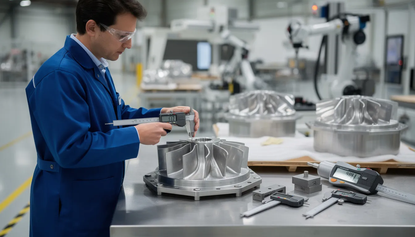
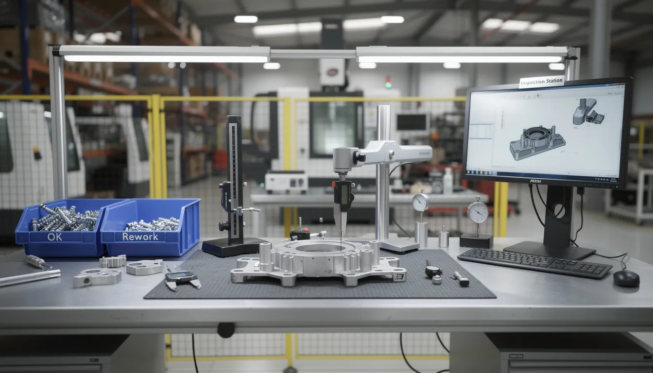
    An aerospace quality inspector is carefully reviewing a machined component on an inspection bench, ensuring that it meets the detailed documentation requirements outlined in the first article inspection report. The inspector focuses on verifying dimensions and critical features of the new part to ensure compliance with aerospace standards.

    Fast Answers: What Each AS9102 Form Is For

    • Form 1 is Part Number Accountability. It identifies what part, assembly, or subassembly is being inspected, including part number, revision, drawing identifiers, purchase order information, and linked FAIRs.
    • Form 2 is Product Accountability. It documents materials, process specifications, special processes, finishes, and functional tests required by the drawing, model, specifications, or customer contract.
    • Form 3 is Characteristic Accountability. It records all product characteristics, including dimensions, tolerances, GD&T, drawing notes, finish callouts, and inspection results.
    • The AS9102 standard establishes documentation requirements for the First Article Inspection (FAI) process, which includes three forms: Form 1 for Part Number Accountability, Form 2 for Product Accountability, and Form 3 for Characteristic Accountability.
    • The AS9102 standard outlines three forms for documenting the FAI: Form 1 for Part Number Accountability, Form 2 for Product Accountability, and Form 3 for Characteristic Accountability.
    • The three forms together provide traceability from the part number to material and process evidence to measured characteristics.
    • Incorrect or incomplete information on any one form is a frequent root cause of fair rejection, rework, and delayed approval from aerospace customers.

    In aerospace, quality assurance forms serve as a roadmap and birth certificate for manufactured parts, offering critical quality assurance benefits. AS9102 forms also ensure supply chain traceability, traveling with parts to allow investigation of failures by linking them to materials and manufacturing processes used.

    AS9102 Form 1 – Part Number Accountability

    Form 1 documents what article is being inspected in the first article inspection. That article may be a detail part, an assembly, or a subassembly. Form 1 ties the FAIR to specific part numbers, drawing revisions, model definitions, customer purchase orders, and related lower-level inspections.

    Form 1 is the cover sheet of the article inspection report. OEM quality teams and auditors use it to quickly understand what the first article inspection report covers and how the inspected article relates to the engineering definition. If Form 1 is wrong, the customer may not trust the rest of the report.

    AS9102C, released on June 28, 2023, is the current version. AS9102B was released on October 6, 2014, and AS9102A was released on January 13, 2004. Current submissions should follow the C layout when AS9102C is required, although legacy FAIRs may still exist in older AS9102A or AS9102B formats.

    Typical Form 1 data includes:

    Form 1 item

    What it controls

    Part number and part name

    Confirms the article being inspected

    Drawing number and drawing revision level

    Connects the FAIR to the engineering definition

    FAI report number or FAIR identifier

    Provides a unique tracking reference

    FAI type

    Identifies full FAI, partial FAI, or re-inspection scope

    Organization name and CAGE code

    Identifies the supplier organization

    Purchase order number

    Links the inspection to the customer contract

    FAI completion date

    Shows when the inspection was completed

    Reviewed and approved fields

    Records the responsible person or people for FAIR approval

    Nonconformance indication

    Identifies whether documented nonconformances are included

    Form 1 of AS9102 requires identification of the part and associated sub-assemblies, while Form 2 must account for all material and process specifications, including any special processes and functional testing defined as design requirements. For assemblies, Form 1 should identify the higher-level assembly and list the associated sub assemblies or lower-level parts. If those sub-assemblies have their own first article inspection fai submitted separately, the related FAIR identifiers should be listed or referenced.

    Evidence that belongs with Form 1 includes:

    • Engineering drawings or model definition matching the part number and revision.
    • Bill of material or configuration list for assemblies.
    • Applicable change notices, such as ECPs, ECOs, ECNs, or customer-approved deviations.
    • Purchase order and contract documents that confirm part number, revision, quantity, and customer requirements.
    • Customer approvals when the customer controls the part number, drawing, or revision.

    Common Form 1 mistakes include:

    • Part number, dash number, or suffix does not match the latest purchase order.
    • Drawing revision on Form 1 does not match the attached drawings or model-based definition.
    • Part name or drawing number is inconsistent between Form 1 and the engineering package.
    • FAI type is marked as full when only partial article inspection was performed after a minor change.
    • Partial FAI is selected but the reason for the partial FAI is missing or weak.
    • Related lower-level FAIRs are not listed for multi-level assemblies.
    • PO or contract number is incomplete, making customer traceability difficult.

    In practice, many of these errors are transcription problems. A digital platform like Connect981 can reduce the risk by auto-populating Form 1 from ERP, MES, and PLM data. The useful control is simple: part number, revision, PO, and drawing information should come from governed source systems rather than being typed repeatedly into spreadsheets.

    AS9102 Form 2 – Product Accountability (Materials, Processes, and Functional Tests)

    Form 2 documents the article’s material specifications, special processes, finishes, and functional tests. This is often where aerospace suppliers run into the most documentation gaps because the evidence may come from mills, distributors, outside processors, internal test teams, or customer-furnished material records.

    Product accountability means proving that all required material, process, and functional test requirements in the drawing, model, specifications, and customer contract have been correctly applied and verified. The form is not just a list of suppliers. It is the bridge between engineering requirements and the actual materials and processes used to produce the article.

    Key Form 2 categories usually include:

    • Raw material specifications, such as AMS, MIL, EN, ASTM, or customer-specific standards.
    • Material type used, including alloy, temper, condition, heat number, lot number, or batch reference.
    • Special processes such as heat treat, NDT, shot peen, welding, brazing, anodizing, passivation, coatings, and plating.
    • Standard manufacturing processes when they have explicit specification callouts.
    • Functional and performance tests, such as proof load, pressure, electrical, torque, leakage, environmental, or operational tests required at the first article inspection stage.

    Evidence that belongs with Form 2 includes:

    Category

    Evidence to attach or reference

    Raw materials

    Mill certificate or distributor certificate with heat or lot number matching the part or batch

    Special processes

    Certificate of Conformance, process results, processor name, approval status, and exact specification revision

    Functional testing

    Test report or results summary tied directly to the FAI unit or lot

    Test equipment

    Calibration certificate where equipment status must be verified

    Customer-furnished material

    Records showing receipt, identity, and use of the furnished material

    A common example is plating. If the drawing requires a specific plating specification and revision, the Form 2 entry should reference the exact specification and the supplier certificate should show the same requirement. A generic note such as “per customer spec” is not enough. If the drawing requires AMS 2411 Rev E and the certificate references AMS 2411 Rev C, the customer will likely reject the FAIR or require clarification.

    AS9102C removed the signature field on Form 2 that existed in AS9102B. One of the significant changes from AS9102B to AS9102C includes the removal of the signature field in Form 2 and Form 3, which has been renumbered as a result. Overall review and approval are handled through the designated approval fields, primarily on Form 1.

    Common Form 2 mistakes include:

    • Missing material certificate or certificate that lacks heat or lot traceability.
    • Outdated specification revision listed on Form 2.
    • Processor certificate not traceable to the part number, PO, serial number, or lot.
    • Special process provider not approved by the customer where approval is required.
    • Functional tests performed but results are not summarized clearly.
    • Test results are attached but not tied directly to the first article unit.
    • “Per customer spec” notes are used without a document number and revision.
    • Confusion about when a special process needs its own FAIR versus when a detailed Certificate of Conformance is sufficient under AS9102C Section 1.3.

    Build-to-print parts usually have direct drawing and specification callouts that drive Form 2. Build-to-spec work and repair or overhaul work can be more layered. In MRO environments, Form 2 may need to reflect OEM requirements, maintenance manual requirements, repair scheme requirements, and customer-specific instructions. The constraint is not only whether the process was performed. The supplier must show that the correct requirement was identified and verified.

    A connected operations layer like Connect981 can centralize material certs, special process CofCs, and test reports. That makes Form 2 population faster, but more importantly, it makes audit retrieval practical when a customer asks for evidence months or years later.

    A technician is inspecting a machined part against an article inspection report on a clean workbench, ensuring that the dimensions and materials meet the requirements for the first article inspection. The scene emphasizes the importance of documentation and verification in the aerospace industry.

    AS9102 Form 3 – Characteristic Accountability, Verification, and Compatibility Evaluation

    Form 3 is where every design characteristic is listed, ballooned, and matched to actual inspection results for the first article. It is the most detailed part of the first article inspection report and the place where customers often spend the most review time.

    Form 3 of AS9102 mandates that all product characteristics, such as dimensions and tolerances, must be documented, and an inspection drawing or model is required to clearly identify these characteristics with uniquely numbered inspection balloons. This includes dimensions, GD&T, datum references, drawing notes, finish callouts, marking requirements, thread requirements, and other characteristics defined by the engineering package.

    Suppliers typically use ballooned drawings or annotated 3D models:

    • Each design requirement receives a unique balloon or characteristic number.
    • The balloon number corresponds to a characteristic number on Form 3.
    • The requirement is recorded with the nominal value, tolerance limits, or specification reference.
    • The measured result, pass/fail result, or “verified by test” result is entered in the same row.
    • Nonconforming results are identified and linked to an NCR, concession, deviation, or customer disposition.

    Typical Form 3 row content includes:

    Form 3 row item

    Purpose

    Characteristic number

    Ties the row to the ballooned drawing or model

    Reference location

    Identifies sheet, zone, view, section, model element, or PMI feature

    Requirement

    Records dimension, tolerance, GD&T symbol, finish, or note

    Nominal and tolerance limits

    Defines the acceptance range

    Result

    Shows actual measured value or verified test outcome

    Inspection method

    Identifies CMM, calipers, thread gage, go/no-go gage, visual inspection, or test method

    Nonconformance field

    Indicates whether the result failed and links to disposition

    Additional data or comments

    Provides needed clarification without replacing objective results

    The discipline here is coverage. “All characteristics” means more than major dimensions. It includes critical notes, general tolerance requirements, special marking, surface finish, thread callouts, sealant notes, and requirements embedded in digital product definition.

    AS9102C removed the per-form signature column from Form 3 as well. The standard now emphasizes clear recording of inspection results and dispositions rather than multiple signature blocks on every form. The signature and approval control is consolidated through the required FAIR review and approval process.

    Common Form 3 mistakes include:

    • Missing characteristics because drawing notes or flags were not ballooned.
    • Combining multiple distinct requirements into one row, making traceability unclear.
    • Recording “OK” or “PASS” instead of actual measured values where numeric results are required.
    • Using sampling when the customer or AS9102 requires 100 percent verification for the first article inspection fai.
    • Failing to update Form 3 after engineering changes between prototype runs and the current FAI run.
    • Missing inspection method or tool information.
    • Not documenting the source of tolerances derived from general notes, title block tolerances, or company standards.

    AS9102C emphasizes the inclusion of verification against digital specifications, such as multi-dimensional CAD files, which was a notable advancement in the standard. For model-based definition, verification evidence may include CMM programs referencing the 3D model, PMI-linked inspection plans, digital clearance checks, or software-based tolerance analysis. The evidence can be digital, but it still must be traceable to each recorded characteristic on Form 3.

    Connect981 can link Form 3 rows directly to inspection plans, in-process checks, CMM output, and defect records. The value is not only fewer keystrokes. The value is maintaining a controlled audit trail from the ballooned requirement to the actual result and any nonconformance disposition.

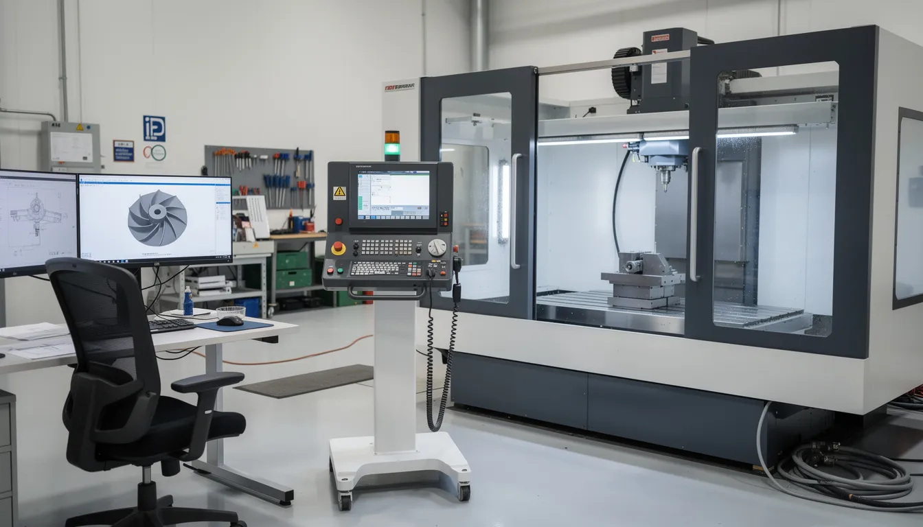
    An inspector is using a coordinate measuring machine to conduct a detailed first article inspection of an aerospace component, ensuring that the dimensions and specifications are met according to AS9102 standards. The process involves verifying the critical features of the new or revised part and documenting the results for the article inspection report.

    How the Three AS9102 Forms Work Together in a First Article Inspection Report

    A complete first article inspection report includes all three AS9102 forms plus supporting evidence: drawings, models, certs, test reports, calibration records when applicable, and nonconformance records. The report should show that the production run used to create the FAI article was controlled, understood, and capable.

    An AS9102 First Article Inspection Report (FAIR) ensures that the production process is stable, repeatable, and capable of conforming to strict safety standards. It is not required for every batch. AS9102 FAIRs are triggered by new parts, design changes, process shifts, new suppliers, or extended inactivity of a part.

    The logical flow is straightforward:

    • Form 1 defines the part, assembly, or subassembly being inspected and connects the FAIR to related lower-level FAIRs.
    • Form 2 proves that all material, process, and functional requirements have been met.
    • Form 3 proves that all design characteristics have been verified and recorded.

    Each AS9102 form contains universal identifiers for traceability, repeated across forms to facilitate tracking of inspections. These identifiers typically include part number, FAIR identifier, drawing revision, organization data, and other control information that allows the customer to connect the forms into one coherent package.

    This structure supports AS9100D Clause 8.5.1.3 on production process verification. AS9102 first article inspection provides a standardized way to demonstrate that the manufacturing process can produce conforming parts across the aviation, space, and defense supply chain.

    Aerospace customers use the article inspection report to establish baseline capability, approve suppliers for ongoing production, and support future audits or investigations. When a field issue occurs, the FAIR helps quality and engineering teams trace the article back to its drawings, materials, process certificates, inspection results, and any disposition records.

    Digital traceability across all three forms is increasingly expected, especially when organizations work with multi-dimensional CAD models, complex assemblies, and supplier tiers spread across multiple companies. Connect981 can act as a unified layer between ERP, MES, QMS, PLM, and supplier systems so the data needed for all three forms is consistent, up to date, and available without hunting through emails and shared folders.

    Common Supplier Mistakes That Cause AS9102 FAIR Rejection or Rework

    Many FAIRs are rejected not because the parts are bad, but because the documentation is incomplete, inconsistent, or not aligned with AS9102C expectations. The product may meet the requirement, but if the evidence is weak, the customer still has a problem.

    FAI is typically required when there is a change in design, production process, or when a new supplier is introduced, ensuring that all aspects of the production process are verified. A new or revised part, a tooling change, a process relocation, or a long production gap can all trigger the need to conduct a full or partial FAI before the part moves into full production.

    Common rejection themes include:

    Configuration and revision control issues

    • A previous FAI template is reused and the drawing number or revision is not updated on Form 1.
    • The PO calls one drawing revision while the FAIR references another.
    • Model-based definition and PDF drawings are not aligned.
    • The part number suffix is omitted, which changes the actual configuration being inspected.

    Incomplete coverage of requirements

    • Ballooning covers dimensions but ignores drawing notes.
    • Surface finish, marking, torque, sealant, or packaging requirements are skipped.
    • Form 2 lists heat treatment but does not attach the processor certificate.
    • Form 3 does not include characteristics derived from general tolerance notes.

    Weak traceability

    • Material certs are attached but do not show the heat or lot used for the FAI part.
    • Special process certs do not reference the part number, PO, serial number, or lot.
    • Functional test reports are included but do not identify the FAI unit.
    • A contact person is listed, but the responsible organization cannot provide the backup evidence during review.

    Poor measurement recording

    • “OK” is entered where a numeric measured value is required.
    • Inspection methods are missing.
    • Nonconforming results are not linked to an NCR or concession.
    • Sampling is used without customer approval or without a defined basis.

    The impact is predictable: repeated customer feedback loops, additional review time for quality engineers, delayed release into the first production run or ongoing production run, and avoidable pressure on program schedules.

    Standardized templates, training, and digital workflows reduce this risk. The goal is not to make the paperwork prettier. The goal is to ensure every required field is completed, every attachment is present, every revision is current, and every result is traceable before submission.

    A typical aerospace supplier moving from spreadsheet-based FAIRs to a digital article inspection workflow can use Connect981 to enforce required fields, compare drawing revision data against ERP and PLM, flag missing certificates, and check that Form 3 balloon counts match recorded rows before the FAIR goes to the customer.

    Making AS9102 First Article Inspection Digital and Audit-Ready with Connect981

    The form-by-form discipline matters, but the larger operational problem is data continuity. Aerospace suppliers often manage FAIR evidence across ERP records, MES travelers, QMS nonconformance logs, supplier emails, shared folders, CMM files, and paper inspection sheets. That fragmentation creates risk.

    Connect981 is built as an aerospace operations platform for connected shopfloor execution, supplier collaboration, and compliance-ready documentation. For AS9102 forms, the platform supports:

    • Preconfigured templates aligned to AS9102C Forms 1, 2, and 3.
    • Automatic population of part, drawing, and revision data from ERP or PLM into Form 1.
    • Central repository for material certs, special process CofCs, and test reports feeding Form 2.
    • Integration with inspection stations and CMM output to populate Form 3 with measured results.
    • Digital work instructions and version control for the routing used to produce the FAI article.
    • Defect logging and nonconformance linkage when results are out of tolerance.
    • Supplier workflow integration so external processors and sub-tier suppliers provide evidence in a controlled process.

    For operations leaders, manufacturing engineers, quality managers, and supply chain teams, the outcome is practical:

    • Reduced FAIR cycle time and fewer customer rejections.
    • Consistent article inspection practices across factories and suppliers.
    • Audit-ready traceability for AS9100, FAA, EASA, ITAR, and customer-specific requirements.
    • Better visibility into documentation readiness before a part reaches customer review.
    • Faster investigation when a material, process, or inspection issue is identified.

    Connect981 can be used for both production FAIs and MRO-related first article inspections when new repair routes, repairs, or modifications are introduced. The platform’s low- and zero-code workflow builder lets teams adapt AS9102 templates for customer-specific FAIR formats without relying on heavy custom IT projects.

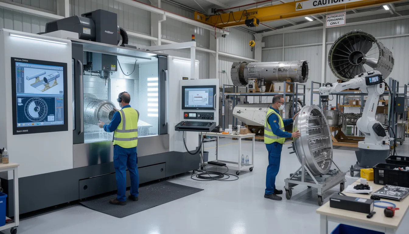
    An aerospace shopfloor technician is using a tablet next to well-organized workstations, ensuring that the documentation requirements for first article inspection (FAI) are met. The technician is focused on reviewing detailed article inspection reports related to new or revised parts and sub-assemblies.

    To see how this works in practice, request a demo of Connect981 and review a live digital AS9102 first article inspection workflow from drawing ballooning through FAIR submission.

    Where to Go Next: Broader AS9102 and FAI Resources

    This article focused on the three AS9102 forms and the documentation mistakes that commonly create rework. Teams that need broader guidance should also review when FAI is required, how full and partial FAI decisions are made, and what re-inspection triggers apply after a change.

    Useful next resources:

    • Read a broader What is AS9102 First Article Inspection? guide covering when FAI is required, full vs partial FAI, and re-inspection triggers.
    • Use an article inspection checklist for aerospace suppliers to prepare drawings, certs, test reports, and approvals before customer submission.
    • Review Connect981 resources for example AS9102 templates, digital FAIR dashboards, and supplier-ready inspection workflows.
    • Verify the current revision before finalizing FAIR templates. AS9102C was released on 2023-06-28, and customer-specific requirements can evolve beyond the baseline standard.
    • For the source standard, confirm requirements through SAE International’s AS9102C publication.

    Mastering as9102 forms turns first article inspection from a paperwork burden into a repeatable process. With clear documentation, disciplined revision control, and the right digital workflow, suppliers can provide better evidence, reduce customer rework, and support quality and on-time delivery.

  • Delta FAI vs Partial FAI: Practical Triggers, Examples, and Documentation

    Delta FAI vs Partial FAI: Practical Triggers, Examples, and Documentation

    A delta fai is a change-focused first article inspection update. A partial FAI is the broader AS9102 term for re-inspecting only the affected portion of a previously approved first article inspection report. In supplier quality work, the two are often treated as the same inspection type, but the scope and trigger matter.

    This article stays in the supplier-side reality of aerospace and defense: AS9100 procedures, AS9102 FAIR forms, OEM purchase order clauses, engineering drawing revisions, raw materials, special process evidence, and customer requirements.

    Answering the core questions up front

    • What is a delta FAI? Delta FAI is a specialized quality control process used in aviation, aerospace, and manufacturing. It verifies only the design characteristic, process, or material changes since the last accepted FAIR.
    • What is a partial FAI? A partial first article inspection is an AS9102 revalidation of selected characteristics, raw materials, or process steps, while the previous full FAI remains the baseline.
    • What triggers each? A delta fai is usually triggered by isolated changes, such as an ECN, model revision, tolerance change, drawing notes update, or surface finish addition. A partial fai may also be triggered by a manufacturing process change, tooling change, new machines, new suppliers, location move, or resuming production after a long gap.
    • What must be resubmitted? Usually an updated article inspection report, the affected fair forms, revised balloon drawings, updated raw material record, special process evidence, dimensional data, and any functional tests tied to the change.
    • How should it be documented? The fai report should clearly state the baseline FAIR, reason for the partial or delta FAI, affected balloons, actual value results, inspection method, engineering documentation, and remaining characteristics referenced from the prior FAIR.

    Terminology note: In aerospace and manufacturing, Delta FAI cannot be directly compared to financial aid programs. Financial Aid Information generally refers to the collective data, deadlines, and guidelines students must navigate to secure funding. FAFSA (Free Application for Federal Student Aid) is the mandatory federal form used to determine eligibility for financial assistance. Eligibility for Title IV financial aid requires enrollment in an eligible degree program, maintaining Satisfactory Academic Progress (SAP), and not defaulting on previous loans. Mistakes on the FAFSA can alter the amount of need-based grants or subsidized loans received. The Student Aid Index (SAI) is calculated by the government to determine how much financial aid a student qualifies for. When referencing a “delta” in a financial assistance profile, it often indicates a recalculation or adjustment to the aid package. Delta-specific financial aid relies on specific, localized criteria.

    Connect981 helps teams standardize delta and partial FAI workflows, but the core issue is operational discipline: know what changed, inspect what is affected, and document the decision so relevant stakeholders can reconstruct it later.

    What is a First Article Inspection in practice?

    A first article inspection is a formal verification that a manufacturing process consistently produces parts conforming to design intent by comparing a production-representative unit’s characteristics to engineering documentation and contract specifications. First article inspections (FAIs) are essential for ensuring that new and revised products conform to design specifications, helping to minimize the risk of defects and safety hazards in the final product. FAIs are most common in aerospace, automotive, defense, and medical manufacturing, where precision and compliance with specifications are critical.

    In aerospace, a first article inspection fai package is normally built to AS9102, maintained by the international aerospace quality group. A First Article Inspection Report (FAIR) consists of three forms plus a balloon or bubble drawing, which identifies the characteristics that the inspector needs to check during the FAI process. The AS9102 standard for aerospace requires that the FAIR includes three specific forms: Form 1 for Part Number Accountability, Form 2 for Product Accountability, and Form 3 for Characteristic Accountability.

    FAI validates the manufacturing process by confirming that it consistently produces parts that conform to design intent, which is crucial for maintaining quality control in production. It is not a “golden part” exercise. First articles should come from the first production run using final raw materials, tooling, programming, inspection plan, hand tools, fixtures, gage i.d. controls, and the intended production process. Conducting a first article inspection can fulfill the process validation requirement for quality management systems such as ISO9001 or AS/EN9100, reinforcing compliance in manufacturing processes.

    The first article inspection process typically involves seven steps, including identifying the need for FAI, conducting the first production run, selecting a sample, performing the inspection, recording results, generating the inspection report, and obtaining review and approval. The first article inspection report, article inspection report, article inspection report fair, and FAIR all refer to this approval process in many OEM quality clauses. A full FAI establishes the baseline before full scale production begins; partial and delta FAIs update that baseline when change occurs.

    An inspector is carefully measuring a machined aerospace component using calibrated tools on a clean workbench, ensuring adherence to quality control standards and design specifications as part of the first article inspection process. The scene highlights the importance of precision in the manufacturing process within the aerospace industry.

    Definition: Partial FAI vs Delta FAI

    In most AS9102 programs, “partial FAI” is the official language. “Delta FAI” is the common shop-floor name for inspecting only the delta against the last approved FAIR. Partial First Article Inspection (AS9102) is relevant in engineering and aerospace fields, especially where a new or revised part must be proven without repeating every unchanged feature.

    Partial first article inspections, also known as Delta FAIs, are necessary when there are changes to a part’s design or production process, including new materials, tooling, or machines that could impact its fit, form, or function. A Full FAI establishes the production baseline for a process and serves as a reference for future Partial FAIs, ensuring that any changes do not adversely affect the product’s compliance with specifications.

    Common naming differences:

    • A bracket Rev B to Rev C changes two hole diameters. One customer calls it delta fai; another calls it partial FAI.
    • A drilling operation moves from Machine 1 to Machine 2. That is often partial FAI because the design did not change.
    • A note adds laser cutting edge quality requirements. Many suppliers call it delta FAI because the engineering drawing changed.

    Triggers for Full, Partial, and Delta FAI (with supplier-side examples)

    Use this as a practical trigger matrix, then verify customer specifications and your quality management system before cutting metal.

    Change type

    Typical expectation

    Supplier-side example

    New part number, new assembly, or first production run manufacture

    full fai

    A new bracket is released and must be inspected across all characteristics before mass production or full scale production.

    Drawing or model revision

    Delta or partial FAI if limited; full FAI if broad

    Chamfer C3 changes from 0.5×45° to 0.25×45°, or customer requirements force full reinspection.

    Raw material change

    Partial FAI, sometimes full FAI

    Switching from 7075-T6 to 7050-T7451 plate changes product specifications and likely affects process capability.

    Same spec, new mill or heat lot

    Partial FAI

    A new 15-5PH bar source requires Form 2 product accountability and selected dimensional record checks.

    Special process change

    Partial FAI

    Anodize moves to a different NADCAP-approved processor; update special process records and related surface finish checks.

    Machine, program, or tooling change

    Partial FAI

    A 5-axis operation moves from Supplier A in Wichita to Supplier B in Querétaro. Recheck affected datums, holes, and surface requirements.

    Production gap

    Often full FAI

    Full first article inspections (FAIs) are required for new parts, new suppliers or facilities, or if the part has not been manufactured in at least two years. AS9102 practice often treats 24 months as the rule of thumb.

    Customer-directed re-FAI

    Follow the purchase order

    Some OEMs require full FAI on every drawing revision, even when the standard allows partial scope.

    When fit, form, or function is potentially impacted, buyers usually expect at least partial FAI. If the change touches safety-critical characteristics, CTQ dimensions, or interface features across multiple parts, full FAI may be cleaner than a complex partial.

    Delta FAI: how it actually works on the shop floor

    A delta fai is change-focused FAI. The scope should be tied to a specific ECN, router revision, tooling NCR, corrective action, or updated design requirements. The supplier references the baseline FAIR, identifies affected balloons, selects first articles from the first production run after the change, performs targeted inspection, and updates form 3 characteristic accountability.

    On the part number accountability form, the reason should be explicit: “Delta FAI due to ECN 23-147 changing chamfer C3 from 0.5×45° to 0.25×45°.” Do not write “drawing changed” and expect a smooth review.

    For assembly fai, the same logic applies. If a valve assembly gets a new gasket and fastener type, inspect interface dimensions, torque, leak functional tests, and any adjacent requirements. Reference existing component FAIRs for remaining aspects that did not change.

    Connect981 can help automate impacted balloon identification and generate a delta table for inspectors. That reduces manual revision comparison, especially where balloon drawings have tens to hundreds of characteristics.

    A quality inspector is reviewing a tablet that displays an article inspection report alongside a machined component and various inspection equipment. This scene highlights the importance of quality control in the manufacturing process, particularly in the aerospace industry, ensuring adherence to design specifications and customer requirements.

    Partial FAI: broader but still scoped resubmission

    Partial FAI is used when the change is significant but does not justify remeasuring every characteristic. Examples include replacing all roughing tools on a titanium bracket, changing from manual TIG weld to robotic MIG on a weldment, or moving a drilling process to a new cell.

    The scope may include all features on one face, all threaded holes, all special process-related features, or all dimensions tied to a new casting vendor. It can also include inspection method changes, such as moving from hand tools and scrape testers to CMM or optical measurement.

    A partial FAI after changing anodize line should update Form 2 with processor data, certifications, and specification requirements. Form 3 should recheck coating thickness, surface finish, masking zones, and any affected drawing notes. The remaining characteristics can reference the previous FAIR if the customer allows it.

    What must be resubmitted in delta vs partial FAI

    Both delta and partial FAI are updated FAIR submissions. The article inspection report format should make scope visible without forcing the reviewer to infer it.

    • Form 1, Part Number Accountability: List part number, revision, purchase order, production run manufacture date, manufacturing location, and reason for partial FAI. Many suppliers keep the original FAIR number and add a suffix, such as FAIR-10023-REV C-DELTA1.
    • Form 2, Product Accountability: Update new or revised raw material records, supplier names, heat lots, material certs, and special process details. Unchanged material and process items can reference the previous FAIR.
    • Form 3, Characteristic Accountability: Record affected design characteristic rows, measured actual value, dimensional data, inspection equipment, and disposition. A characteristic accountability form should also show “no change from baseline FAIR” for remaining characteristics when required.
    • Balloon drawings: Keep original balloon IDs where possible. Mark changed balloons with a color, revision cloud, or Δ prefix. Ensure the engineering drawing revision matches the FAIR.
    • Required fields: Each form in the FAIR must include fields that are always necessary, such as part number, date, and signature, as well as conditionally required fields like part serial number and tool identification number.

    FAI software tools can automate the creation of First Article Inspection Reports (FAIRs), reducing manual transcription errors and speeding up the reporting process. Automation in FAI processes, such as ballooning tools, can overlay unique IDs on drawings or 3D models, mapping each design characteristic to a characteristics table, which improves inspection plan creation and audit clarity.

    Examples by change type: when delta FAI is enough vs when you need more

    • Minor dimensional change: A machined bracket Rev C tightens one hole tolerance and changes a chamfer. Delta fai is appropriate. Reinspect those balloons, adjacent position callouts, and any affected reference standard.
    • Process change: A supplier switches from 3-axis milling with manual deburr to 5-axis simultaneous machining with automated edge-break. A broader partial FAI is safer. Recheck profile, edge-break notes, surface finish, and features produced by the revised path.
    • Raw material substitution: A mill change for 15-5PH bar may only require partial scope if alloy and temper remain unchanged. A temper change requires more scrutiny, Form 2 updates, and selected hardness or mechanical property objective evidence.
    • Laser cutting: A flat pattern moves from punched blanks to laser cutting. Inspect edge quality, hole size, burr condition, heat-affected zones if specified, and downstream bend dimensions.
    • Assembly change: A valve assembly receives a new gasket. Delta FAI can cover torque, compression height, leak testing, and interface dimensions while referencing existing FAIRs for unchanged components.
    • Run at rate issue: If a pilot lot passes but the run at rate exposes tool deflection, the customer may require corrective action and a partial FAI tied to the corrected manufacturing plan.

    Documentation expectations in the FAIR for delta and partial FAI

    Buyers, auditors, and regulators expect a clear digital thread: what changed, why article inspection was repeated, which characteristics were reverified, and how the update ties to prior FAIRs.

    A useful delta table includes:

    • Balloon number and drawing zone
    • Previous requirement and current requirement
    • Nature of change, such as added note or tightened tolerance
    • Action, such as reinspect, reference, deleted, or not applicable
    • Evidence, including dimensional record, certificates, or functional test report

    Attach ECNs, ECAs, updated models, revised routings, material certificates, special process approvals, and test reports. Do not leave unchanged fields blank. Record “no change” and cite the baseline FAIR. That simple discipline helps ensure completeness during the approval process.

    Managing repeated FAIs across a complex supply chain

    Complex aerospace industry programs often involve multiple parts, sub-tier processors, frequent revisions, and suppliers working from different data packages. When FAIRs live in spreadsheets, PDFs, and email threads, one supplier may resubmit full FAI unnecessarily while another reuses an outdated baseline.

    A connected system like Connect981 centralizes FAIRs, engineering changes, supplier data, digital work instructions, and routing revisions. It can flag when new ECNs, router changes, or inspection plan updates should trigger delta or partial FAI. Shared templates for form 3 characteristic accountability and dashboards for late FAIR updates reduce duplicate work.

    AI tools, like speech recognition technology, can enhance the efficiency of FAI processes by allowing users to capture data verbally, which can lead to a significant reduction in inspection time and improved accuracy in reporting.

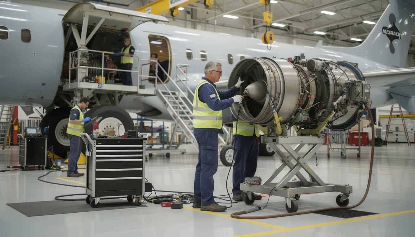
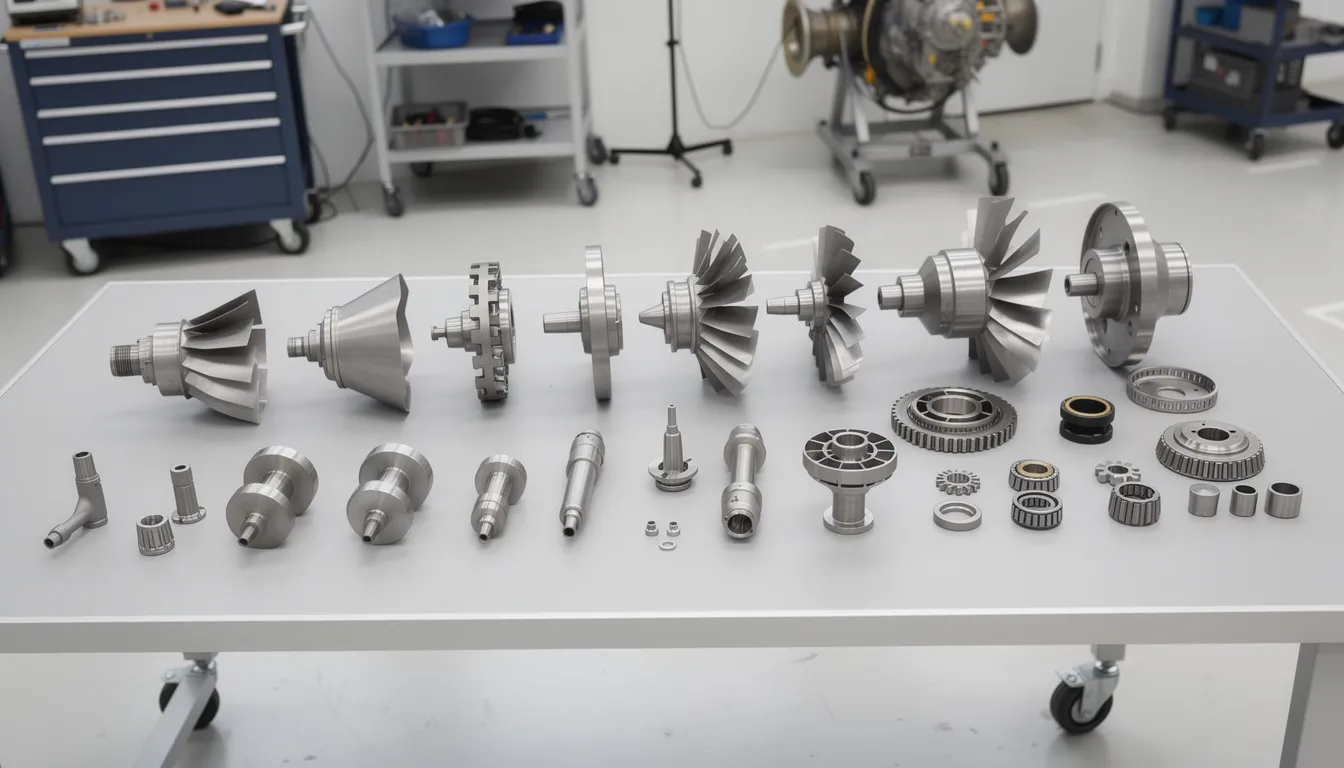
    The image shows various aerospace components neatly arranged next to inspection tools and a tablet in a factory setting, highlighting the importance of the first article inspection process in the aerospace industry. This setup emphasizes quality control and the manufacturing process, essential for ensuring that production runs meet customer specifications and design requirements.

    Practical checklist: deciding and executing delta vs partial FAI

    Use this before cutting metal:

    1. Identify the change type: design, raw materials, tooling, machine, location, special process, inspection method, or production gap.
    2. Ask whether fit, form, function, safety, or customer specifications are affected.
    3. Check the purchase order, AS9100 quality management system procedure, and OEM flow-downs.
    4. Decide full FAI, partial FAI, or delta fai. If scope becomes confusing, choose full FAI or get customer agreement.
    5. Define affected balloons, adjacent dimensions, and remaining aspects to reference.
    6. Confirm raw material record, product accountability, and special process evidence.
    7. Select first articles from the first production run after the change.
    8. Record actual value results, inspection tools, signatures, and dates.
    9. Review with relevant stakeholders before shipment.
    10. Store the decision logic so future audits can understand the process.

    Teams can embed this checklist as a zero or low-code workflow in Connect981, making the same decision path available across programs, factories, and suppliers.

    Summary: using delta and partial FAI to protect quality without drowning in paperwork

    Full FAI establishes the baseline. Partial FAI covers broader but scoped change. Delta FAI is targeted revalidation of clearly identified changes against the last approved FAIR.

    The goal is not to avoid first article inspection. The goal is to right-size it: enough inspection to protect quality, not so much that unchanged features create time consuming rework. Clear Form 3 documentation, disciplined balloon control, and a readable change log make the FAIR useful to buyers, regulators, and future engineers.

    If your team wants to standardize delta and partial FAI workflows, reduce manual report handling, and improve supply chain visibility, request a demo of Connect981.

  • What is MWI in manufacturing?

    In most manufacturing contexts, especially regulated environments, MWI usually means “Manufacturing Work Instructions” (sometimes written as “Manufacturing Work Instruction” or simply “Work Instructions”). These are the controlled documents or digital instructions that tell operators exactly how to perform a manufacturing, assembly, test, or inspection step.

    What are Manufacturing Work Instructions (MWI)?

    Manufacturing work instructions typically include:

    • Step-by-step tasks for a specific operation or workstation
    • Required tools, fixtures, gauges, and materials
    • Key parameters such as torques, temperatures, speeds, or tolerances
    • Inspection and verification points (including who signs off and how)
    • Links or references to higher-level procedures, drawings, and specifications
    • Revision information, approvals, and effective dates controlled through document or change control

    In digital environments, MWI may be delivered through MES or a digital work instruction system, often tied to specific part numbers, configurations, or serials to support traceability.

    Why the meaning of MWI can differ by site

    Acronyms are not fully standardized across industry. At some plants, MWI might be called WI, EWI (electronic work instructions), or SOP, and the acronym MWI may not be used at all. In others, MWI might mean something more specific, such as “Machining Work Instruction” or “Maintenance Work Instruction,” depending on local conventions.

    Because of this, you should always:

    • Check your organization’s quality manual or document control procedures to confirm the exact definition
    • Verify how MWI is represented in your PLM, MES, DMS, or ERP systems
    • Align on terminology in specifications, contracts, and supplier documentation to avoid ambiguity

    How MWI fits into regulated and brownfield environments

    In regulated or safety-critical manufacturing, MWI is tightly linked to:

    • Document control and change management to ensure operators only see the current, approved instructions
    • Traceability, since executed steps and signoffs often form part of the batch or device history record
    • Validation and qualification, because changing how instructions are authored or delivered can trigger revalidation of processes, software tools, and sometimes product qualifications

    In brownfield plants, MWIs commonly coexist across multiple systems: some on paper, some in shared drives, some embedded in legacy MES screens. Replacing them with a single new digital system can be difficult due to validation burden, integration complexity, and downtime risk, so many organizations move incrementally, standardizing formats and links first and then modernizing delivery over time.

    Practical implications when working with MWI

    When you design or change MWIs in a real plant environment:

    • Involve operations, quality, and industrial engineering to ensure instructions are usable, unambiguous, and compliant.
    • Plan for coexistence with legacy instructions and systems during transition, including operator training and clear identification of superseded documents.
    • Ensure that any system used to author, store, or present MWIs is under appropriate configuration and change control and, where applicable, validated.
    • Confirm that revision changes do not unintentionally break links in MES, PLM, QMS, or ERP routing and BOM structures.

    If your site uses the acronym MWI differently, that local definition should take precedence, but you should document it clearly in your internal glossary or procedures to prevent misinterpretation across teams and suppliers.