RSC Cluster: Data Mapping and System Interoperability

The Data Mapping and System Interoperability Cluster ties execution, planning, quality, and supplier systems together without rip-and-replace projects. It explains how governed data mapping enables interoperability across ERP, MES, QMS, PLM, and external partners. The content positions execution as the truth layer that systems align around. This cluster is the connective tissue of the entire ecosystem.

  • low-code platform

    A low-code platform is a software platform used to build applications, workflows, forms, dashboards, and integrations mainly through visual configuration rather than traditional hand coding. It commonly provides drag-and-drop design tools, reusable components, workflow logic, data models, and connectors to other systems.

    In manufacturing and regulated operations, a low-code platform is often used to create internal business applications such as deviation workflows, digital forms, approvals, maintenance requests, issue tracking, supplier collaboration steps, or simple MES-adjacent and quality processes. It can sit above existing systems like ERP, MES, QMS, or document control tools, or connect to them through APIs and integration services.

    What it includes and what it does not

    A low-code platform usually includes:

    • Visual application and workflow design
    • Prebuilt UI components and templates
    • Rules, logic, and approval routing
    • Data capture forms and basic reporting
    • Connectors or APIs for system integration
    • Security, roles, and deployment controls defined by the platform

    It does not automatically replace core transactional systems such as ERP, MES, PLM, or QMS. It is also not the same as custom software development, even though many low-code platforms allow some scripting or code extensions when needed.

    Operational meaning

    Operationally, a low-code platform is often the layer used to digitize manual or spreadsheet-based processes without building a full custom application from scratch. For example, a manufacturer might use one to create an operator escalation form, an NCR intake workflow, a training acknowledgment app, or a process exception review flow that exchanges data with ERP or MES.

    Where controls matter, organizations typically evaluate how the platform handles access, versioning, change management, audit trails, integrations, and data ownership. Those capabilities vary by product and configuration.

    Common confusion

    Low-code platform is commonly confused with no-code platform. No-code tools are generally aimed at users with little or no programming and rely more fully on configuration only. Low-code platforms usually still support technical users and may allow code for advanced logic, integrations, or user interface behavior.

    It is also commonly confused with an application platform or BPM/workflow tool. A low-code platform may include workflow and application functions, but the term refers more broadly to the development approach and tooling model, not only process automation.

  • API-based KPI access

    API-based KPI access commonly refers to the ability to retrieve key performance indicator data through an application programming interface (API) rather than only through dashboards, spreadsheets, or manual exports. In manufacturing and regulated operations, this usually means systems such as MES, ERP, quality, historian, or analytics platforms expose KPI values, counts, rates, or trends in a machine-readable form for other software to consume.

    The term includes both direct access to calculated KPIs and access to the underlying operational data used to calculate them, depending on how a system is designed. It does not by itself mean that the KPI definitions are standardized, that the data is real-time, or that different systems calculate the same metric in the same way.

    Where it applies

    API-based KPI access appears in workflows where performance data needs to move between systems, teams, or reporting layers. Examples include pulling scrap rate from MES into an enterprise analytics tool, reading schedule attainment from ERP into a plant dashboard, or exposing quality trend data to a reporting application.

    • Operational dashboards and BI tools
    • MES and ERP integration
    • Quality and compliance reporting
    • Data lakes, analytics platforms, and custom applications
    • Cross-site or enterprise performance rollups

    What is typically exposed

    Depending on the platform, API-based KPI access may provide:

    • Current KPI values such as OEE, yield, scrap rate, downtime, or on-time completion
    • Time-series KPI history by shift, work order, line, machine, or site
    • Dimensions and filters such as product, operation, lot, or date range
    • Metadata such as units, timestamps, calculation windows, and data source references

    Common confusion

    API-based KPI access is often confused with KPI visualization. A dashboard shows KPIs to a person, while an API exposes KPI data to another system or script.

    It is also different from general data integration. Data integration may move raw transactions, events, or master data; API-based KPI access is specifically about making performance indicators available programmatically.

    Another point of confusion is real-time access. An API can expose near-real-time, batch-refreshed, or historical KPI data. The term does not guarantee update frequency.

    Operational meaning

    In practice, API-based KPI access supports automated retrieval of operational signals without relying on manual extraction. In regulated manufacturing, this matters when KPI data is reused across reporting, investigations, quality review, or performance monitoring processes, because the source system, timestamps, and calculation logic may need to be understood clearly even when the API access itself is technically simple.

  • RAMI 4.0 Reference Architecture: A Structured Explanation

    RAMI 4.0 Reference Architecture: A Structured Explanation

    Overview: What RAMI 4.0 Represents

    RAMI 4.0, the Reference Architectural Model for Industry 4.0, was initially standardized as DIN SPEC 91345:2016 and later aligned with IEC PAS 63088. It emerged from German industry efforts to provide a structured way of describing the components, relationships, and data flows that characterize modern manufacturing systems. The model is a conceptual, three-dimensional reference architecture, not a concrete system blueprint or implementation method.

    The purpose of RAMI 4.0 is to serve as a shared mental model and common language for describing Industry 4.0 systems, physical assets, and data flows across disciplines. Engineers, software vendors, automation specialists, and standards bodies can use the same coordinate system to discuss where a given technology, standard, or function belongs within a broader manufacturing context. This is particularly valuable in environments where information technology and operational technology must converge.

    The model helps position technologies such as digital twin implementations, OPC UA communication protocols, and smart sensors within a consistent architectural frame. However, RAMI 4.0 remains technology-agnostic. It does not mandate specific products, platforms, or integration patterns. This article is written from Connect981’s perspective as an aerospace and MRO operations platform, using RAMI 4.0 purely as a reference explanation without prescribing adoption or implementation steps.

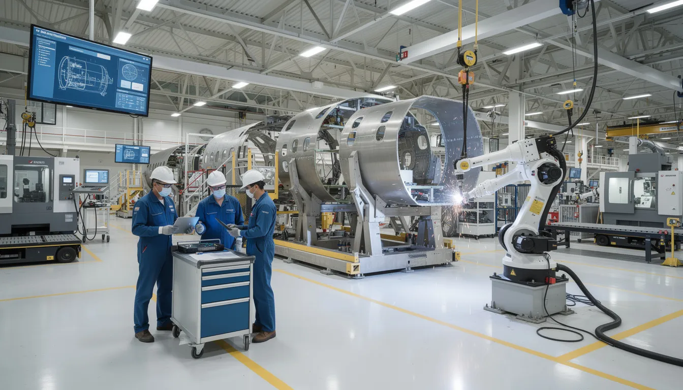
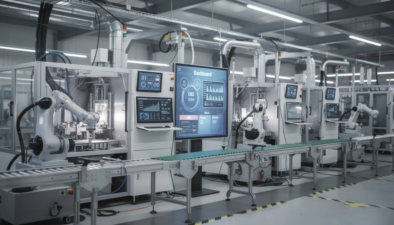
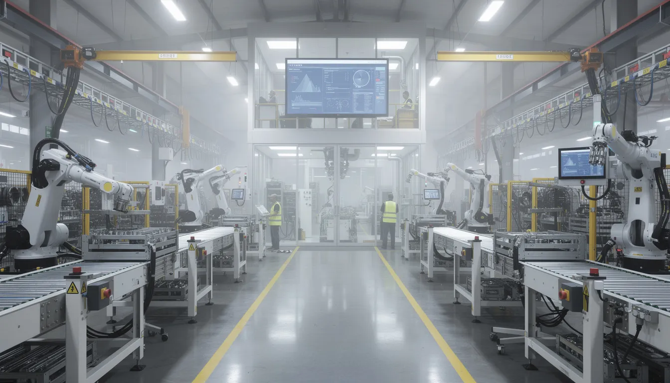
    The image depicts a modern industrial factory floor featuring robotic arms and various automation equipment, illustrating the principles of smart manufacturing and industrial automation. This environment reflects the integration of emerging technologies and communication protocols within the framework of the RAMI 4.0 reference architecture, emphasizing efficiency in manufacturing processes.

    Industry 4.0 Context and Motivation

    The term Industry 4.0 situates current manufacturing transformation within a historical sequence. The First Industrial Revolution brought mechanization through water and steam power. The Second introduced mass production and electrical engineering. The Third applied electronics and information technology to automate industrial processes. The fourth industrial revolution, emerging around 2011 onward, centers on cyber physical systems, the Industrial Internet of Things, and data-driven automation.

    Germany’s “Plattform Industrie 4.0” served as a central driver for this movement. The initiative brought together representatives from mechanical engineering, electrical engineering, and information and communication technology sectors to define a coherent vision for networked production. The goal was not merely to introduce advanced technologies but to enable manufacturing companies to operate with greater efficiency through connected, intelligent systems.

    The complexity of heterogeneous technologies, standards, and domains made a reference architecture necessary. Enterprise IT systems, shopfloor control systems, field devices, and products each brought their own conventions and protocols. Prior models like ISA-95 and IEC 62264 addressed automated interfaces between enterprise and control systems. Life cycle management standards such as IEC 62890 covered industrial system lifecycles. However, neither offered a unified view of Industry 4.0 that could span all these concerns.

    For sectors like aerospace manufacturing and MRO, clear reference models help reason about traceability, digital documentation, and multi-tier supply chain integration. Even if RAMI 4.0 itself does not dictate concrete automation solutions, it provides a vocabulary for discussing where different systems and functions belong in a broader architecture.

    Origins and Standardization of RAMI 4.0

    The development of RAMI 4.0 began around 2013-2015 through the collaborative efforts of German “Plattform Industrie 4.0” working groups, together with VDI (Association of German Engineers) and ZVEI (the German Electrical and Electronic Manufacturers Association). These organizations recognized that without a common framework, Industry 4.0 efforts would fragment into incompatible implementations.

    Key milestones in the standardization process include:

    Milestone

    Year

    Significance

    Initial RAMI 4.0 concept publication

    2015

    ZVEI status report establishing the three-dimensional model

    DIN SPEC 91345

    2016

    German national standard formalizing RAMI 4.0

    IEC PAS 63088

    2017

    International alignment through IEC Publicly Available Specification

    The purpose of RAMI 4.0 from the outset was to harmonize existing and emerging standards, not to replace them. The model gives stakeholders a shared three-dimensional map for positioning international standards and use cases. Government-backed initiatives in Germany aimed to avoid fragmentation by promoting RAMI 4.0 as a common reference, especially for machine builders, automation vendors, and software providers.

    The industrial internet reference architecture (IIRA), developed by the Industrial Internet Consortium, emerged in parallel for broader IIoT contexts. RAMI 4.0 focused specifically on manufacturing and industrial production, reflecting its German manufacturing origins and strong anchoring in European standardization for various industries.

    RAMI 4.0 as a Three-Dimensional Reference Architecture Model

    RAMI 4.0 uses a three dimensional coordinate system to map any Industry 4.0 concept, component, or function. The three axes are:

    • Layers (vertical axis): Representing IT representation of assets
    • Life Cycle & Value Stream (horizontal axis): Representing evolution over time
    • Hierarchy Levels (depth axis): Representing scale from products to connected enterprises

    The visual mental model resembles a three dimensional layer model or grid. Any element can be located by specifying its coordinates on these axes. A sensor’s OPC UA communication function at the work center level during the production phase occupies a specific position within this coordinate system, distinct from an enterprise planning function at the business layer during the design phase.

    The image depicts an abstract three-dimensional grid structure that illustrates a coordinate system with multiple intersecting planes, representing a complex framework for industrial internet reference architecture. This visual metaphor captures the integration of different systems and layers, essential for smart manufacturing and digital transformation in the context of industry 4.0.
    The axes are grounded in existing international standards. The Layers axis arises from IT architecture practice. The Life Cycle & Value Stream axis builds on IEC 62890 principles for life cycle and value chain management. The Hierarchy Levels axis extends IEC 62264 and ISA-95 automation levels, adding a “Product” level at the bottom and “Connected World” at the top.

    The model is descriptive and classificatory. It helps organize thinking and documentation in a structured manner, but it does not prescribe how to build software, design networks, or select technologies. In Connect981’s context, RAMI 4.0 serves as a reference lens to discuss where functions like digital work instructions, traceability, and supplier collaboration would sit in a broader Industry 4.0 architecture.
    Axis 1: Layers (Vertical IT Representation)

    The Layers axis, sometimes called the vertical axis or left horizontal axis in certain visualizations, decomposes how a physical asset is represented and handled in IT systems. The progression moves from physical properties up through data management and business processes. RAMI 4.0 defines six layers, each with distinct responsibilities.

    Asset Layer

    The asset layer focuses on physical entities. These include machines, fixtures, tools, and products with their mechanical and electrical characteristics. In aerospace manufacturing, this might include a serialized composite part, a torque-controlled assembly tool, or a CNC machine. The layer encompasses the physical world, including metal parts, circuit diagrams, QR codes, and documents that represent tangible reality.

    Integration Layer

    The integration layer couples physical assets to the digital world. This is where sensors, controllers, fieldbus interfaces, and initial data acquisition mechanisms reside. For assets that cannot communicate on their own, such as human operators or purely mechanical components, the integration layer provides interfaces like HMIs or barcode scanners. The digital twin concept begins here, creating IT representation of physical assets.

    Communication Layer

    The communication layer provides standardized communication protocols and services for interoperable data transport. Examples include OPC UA, MQTT, and fieldbus gateways. This layer ensures that communication technology enables different systems to exchange data in common formats, regardless of vendor or origin.

    Information Layer

    The information layer structures, contextualizes, and assigns semantic meaning to raw communication data. Data management practices ensure consistent interpretation across systems. Quality attributes, maintenance histories, and production parameters receive formal definitions at this level, supporting semantic interoperability essential for smart manufacturing.

    Functional Layer

    The functional layer defines services, logic, and behaviors. Functions like routing selection, condition monitoring, predictive maintenance rules, and quality check logic reside here. Formal function descriptions support decision logic execution and service-oriented architecture patterns.

    Business Layer

    The business layer models organizational business processes, compliance rules, and economic decisions. In aerospace contexts, requirements from AS9100, FAA, or ITAR regulations would be represented at this level. The layer links manufacturing processes to legal, regulatory, and business objectives, operating above purely technical implementation.

    The Layers axis separates concerns, allowing standards and solutions to focus on specific layers while still fitting into a coherent whole. This supports loose coupling between layers while maintaining high cohesion within each layer.

    Axis 2: Life Cycle & Value Stream (Horizontal Development and Operation)

    The right horizontal axis, or Life Cycle & Value Stream axis, captures an asset’s evolution over time. It spans from initial concept through end-of-life and distinguishes between “Type” and “Instance” perspectives.

    Type Perspective

    The Type perspective addresses generic product definitions, master data, and design models handled before any specific physical instance exists. In aerospace, this might include:

    • A generic engine bracket specification with defined tolerances
    • Master work instructions for a recurring assembly process
    • Design models for prototype production before first article inspection

    Type information represents blueprints and templates that define what something should be.

    Instance Perspective

    The Instance perspective tracks concrete physical items, batches, or machines once produced and deployed. This includes:

    • Serial numbers for individual components
    • Maintenance records for specific engines
    • Modification histories for a particular aircraft

    Instance information represents specific realizations of Type definitions.

    IEC 62890 provides the foundational standard for life cycle management. RAMI 4.0 overlays Industry 4.0 concepts, such as digital twins, onto this time dimension. The axis also encompasses value stream staging from development and prototyping through production, operation, service/maintenance, and decommissioning.

    For aerospace and MRO operations, this distinction matters when discussing traceability. First article inspection relates to validating that an Instance meets its Type definition. MRO overhaul processes track Instance-specific histories against Type-level requirements. The axis does not define individual process steps but provides a comprehensive framework for discussing which life cycle phase a given function or data set relates to.

    Axis 3: Hierarchy Levels (Depth Across Industrial Scale)

    The left horizontal axis represents hierarchy levels, expanding traditional automation levels from IEC 62264 and ISA-95 to reflect modern, connected manufacturing environments. Where traditional models stopped at the enterprise level, RAMI 4.0 extends in both directions.

    Level

    Description

    Aerospace Example

    Product

    Smart products or parts with embedded identification

    Serialized aerospace component with RFID tag

    Field Device

    Sensors, actuators, and drives interacting with physical processes

    Torque sensors on assembly tools, temperature probes in curing ovens

    Control Device

    PLCs, CNC controllers, motion controllers orchestrating field devices

    CNC controller for a 5-axis milling machine

    Station

    Individual machines, workstations, or inspection cells

    Assembly station, automated optical inspection cell

    Work Centers

    Collections of stations forming process areas

    Composite layup area, wing assembly line segment

    Enterprise

    ERP, PLM, and corporate planning systems

    Multi-site production planning, quality management systems

    Connected World

    External networks including customers, regulators, and suppliers

    Supplier data portals, regulatory submission systems

    The “Product” level at the bottom is a significant extension from traditional ISA-95. It recognizes that smart products can actively influence manufacturing processes through embedded sensors or self-optimizing capabilities. This reflects the industrie 4.0 vision where products carry their own production requirements and quality data.

    The “Connected World” level at the top extends beyond enterprise boundaries. In aerospace, this includes interactions with customers, regulatory bodies, and multi-tier suppliers through standards-based interfaces and shared services. The hierarchy levels represent the spectrum from individual components to global supply chain ecosystems.

    Unlike rigid pyramidal hierarchies of earlier models, RAMI 4.0 assumes cross-level communication and more dynamic interactions. Components at any level can potentially communicate with other components, supporting the network-structured architectures that characterize smart factories.

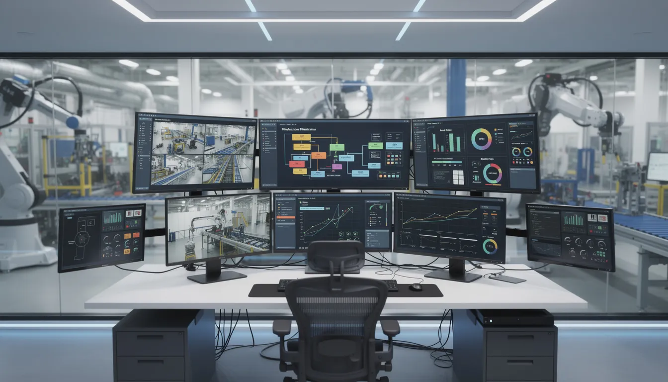
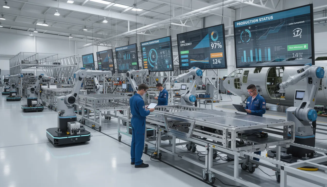
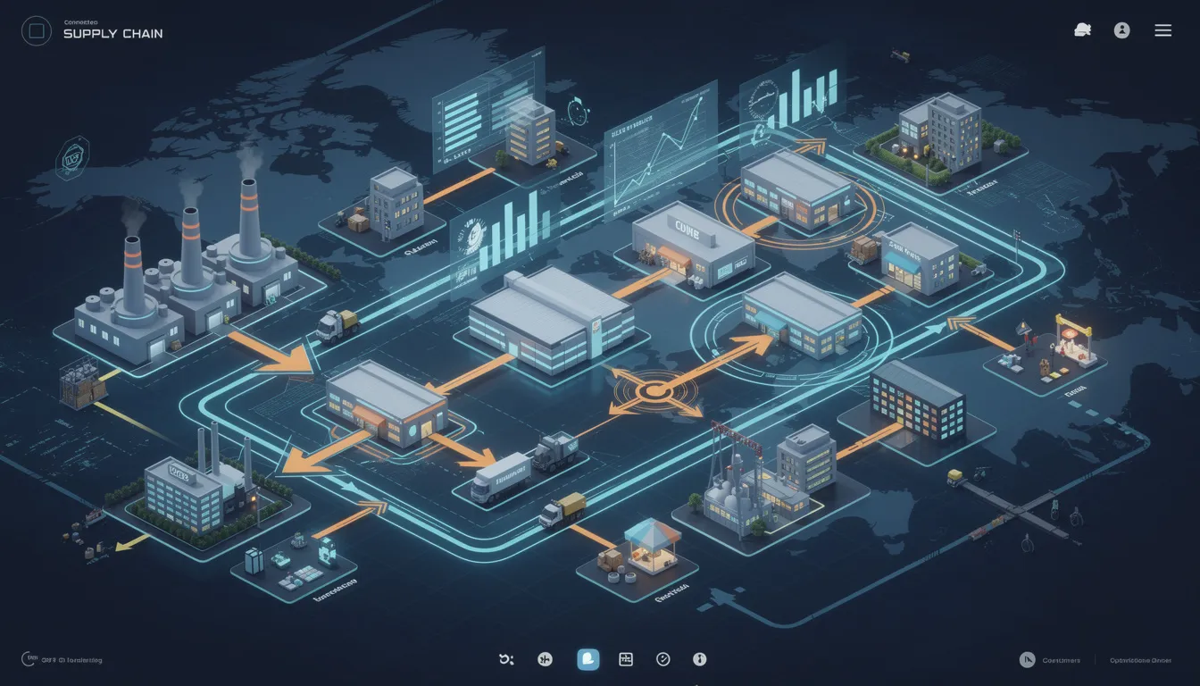
    The image depicts a large industrial manufacturing facility showcasing multiple operational levels, from floor equipment to control rooms, illustrating the integration of advanced technologies and automation solutions in a smart manufacturing environment. This scene represents the principles of the RAMI 4.0 reference architecture, highlighting the importance of communication technology and data management in optimizing industrial processes.

    Purpose and Use of Reference Architecture Models in Industry 4.0

    A reference architecture model is an abstract, standardized way of describing system structures and relationships, independent of particular products. Reference models serve several important aspects in complex systems environments.

    Shared Vocabulary

    Reference architectures provide a neutral, agreed-upon terminology for engineers, software vendors, and policy makers. When stakeholders discuss “where” a function belongs, a reference model gives them common understanding. The hierarchy levels, layers, and life cycle phases provide a structured approach for cross-disciplinary dialogue.

    Classification

    Existing standards, technologies, and use cases can be mapped to specific segments of the model. This clarifies where overlaps or gaps exist. For example, OPC UA clearly maps to the Communication layer, while IEC 62890 informs the Life Cycle axis. This classification supports step by step migration from legacy systems to smart manufacturing environments.

    Alignment

    In complex, multi-partner ecosystems such as aerospace value chain networks, different stakeholders need common perspective on system architecture. A reference model helps align expectations and documentation without requiring every party to use identical products or platforms.

    Analysis

    Systematic analysis becomes possible by locating elements along the three axes and assessing interactions or dependencies. Questions like “what happens when a field device needs to communicate with enterprise systems?” can be discussed using the model’s structure.

    Reference architectures like RAMI 4.0 do not mandate specific products, communication protocols, or platforms. They provide a standardized framework into which solutions can be placed. For platforms like Connect981, reference models inform conceptual discussions about where digital work instructions, traceability functions, or supplier collaboration portals sit in relation to broader Industry 4.0 structures.

    RAMI 4.0 in Relation to Other Industry 4.0 Architectures

    Multiple reference models coexist in the Industry 4.0 landscape. Understanding their relationships helps clarify RAMI 4.0’s specific focus.

    The Industrial Internet Reference Architecture (IIRA), developed by the Industrial Internet Consortium, is domain-independent. It covers a broad range of IIoT use cases beyond manufacturing, including energy, transportation, and healthcare. The IIRA addresses a connected world of industrial applications without the specific manufacturing focus of RAMI 4.0.

    Aspect

    RAMI 4.0

    IIRA

    Primary Focus

    Manufacturing, industrial production

    Broad IIoT across sectors

    Geographic Origin

    Germany, European standardization

    International, US-based consortium

    Life Cycle Integration

    Explicit axis based on IEC 62890

    Less explicit lifecycle dimension

    Hierarchy Model

    Extended ISA-95 with Product and Connected World

    Different functional domains approach

    International organizations have also developed related frameworks. NIST’s CPS Framework addresses cyber physical systems more broadly. Sector-specific models exist for particular industries. Sometimes mappings are created to translate between these architectures.

    Multiple reference models can be used in parallel. An organization might use IIRA for high-level IIoT planning and RAMI 4.0 to describe detailed manufacturing asset interactions. These models are abstract tools for structuring thought and documentation rather than prescriptive roadmaps for digital transformation or technology selection.

    Conceptual Strengths and Limitations of RAMI 4.0

    Strengths

    RAMI 4.0 provides several conceptual benefits:

    • Systematic Structure: The three-axis approach forces stakeholders to specify where, in terms of layers, life cycle phases, and hierarchy levels, a given concept belongs
    • Standards Grounding: Building on established IEC standards gives the model credibility and integration with existing industrial process measurement and automation frameworks
    • Cross-Disciplinary Dialogue: IT, OT, and business stakeholders can use the same coordinate system to discuss complex systems
    • Neutral Framework: Technology-agnostic positioning allows the model to remain relevant as emerging technologies and artificial intelligence capabilities evolve

    Limitations

    Any architectural abstraction carries inherent limitations. RAMI 4.0 is no exception.

    Abstraction Gap: High-level models cannot capture all real-world constraints. Legacy system quirks, specific aerospace regulations, organizational culture, and machine learning integration challenges do not map neatly onto a three-dimensional cube. The gap between model and reality requires additional guidance.

    Static Representation: The model is largely static and structural. Industry 4.0 systems often exhibit dynamic, adaptive behaviors. Real-time reconfiguration, autonomous decision-making by control systems, and event-driven architectures are difficult to express in a static coordinate system.

    Interpretation Variability: Organizations may interpret axes and levels differently. What one company considers a “Work Center” another might classify as a “Station.” This leads to inconsistent mappings and the need for supplementary documentation.

    Scope Boundaries: RAMI 4.0 focuses on industrial production. It does not, by itself, fully address service operations, logistics networks, or detailed cybersecurity models. Other components of a complete Industry 4.0 strategy require additional frameworks.

    RAMI 4.0 should be seen as one analytical lens among several. It structures discussions and documentation effectively but is insufficient on its own to fully specify or guarantee a working Industry 4.0 system. The model identifies where standards and business models might apply but does not resolve all practical challenges of integration.

    Implications for Digital Industrial Operations (Without Prescriptive Guidance)

    For domains like aerospace manufacturing and MRO, a model like RAMI 4.0 can inform thinking without dictating solutions.

    The Layers axis offers a way to discuss where capabilities typically reside:

    • Digital work instructions might span the Information and Functional layers, providing structured data with associated business logic
    • Traceability functions operate across Integration, Information, and Business layers, linking physical assets to semantic data and compliance requirements
    • Quality checks engage Functional layer logic with Business layer rules

    The Life Cycle & Value Stream axis clarifies whether a given data set or function relates to Type or Instance information. Tracking serialized aerospace components across manufacturing and MRO requires distinguishing between master definitions and instance-specific histories. This distinction matters for data management strategies and audit requirements.

    The Hierarchy Levels axis provides vocabulary for indicating whether a function pertains to field devices, stations, work centers, or enterprise and connected world levels. Multi-site coordination and supplier collaboration involve enterprise and connected world interactions, while shopfloor execution focuses on station and work center levels.

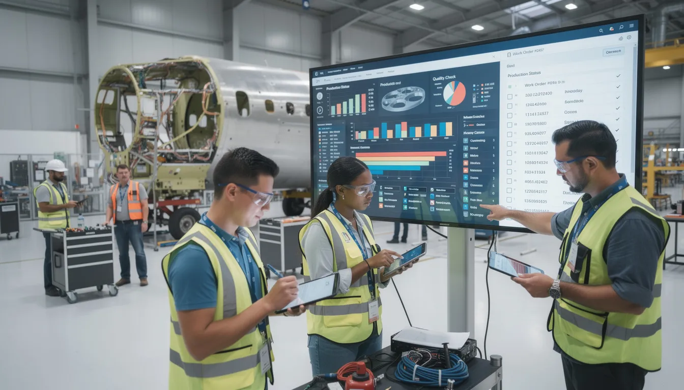
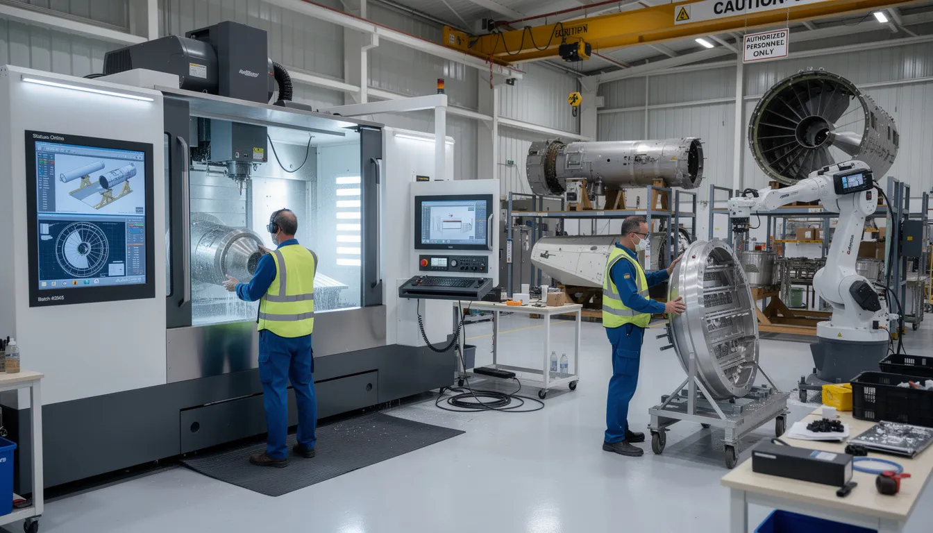
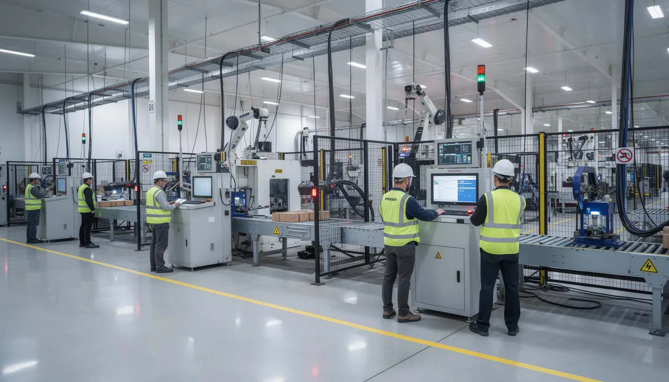
    The image depicts an aerospace manufacturing environment where workers are actively operating advanced equipment amidst digital displays on the factory floor, highlighting the integration of emerging technologies and industrial automation in smart manufacturing processes. This setting reflects the principles of the RAMI 4.0 reference architecture, emphasizing life cycle management and data management in a connected world.

    For platforms like Connect981, RAMI 4.0 acts as a reference backdrop for analysis and communication with stakeholders. When discussing how digital work instructions, traceability, and supplier portals function, the model provides a common language. However, the model does not directly define software modules, integration patterns, or deployment approaches.

    RAMI 4.0 is most valuable as a conceptual reference architecture. It structures how Industry 4.0 scenarios are described and reasoned about in various industries. Practical system design requires additional, more detailed models and decisions beyond the scope of what any single reference architecture can provide. For aerospace and MRO organizations navigating Industry 4.0 concepts, the model offers a starting point for structured discussions rather than a destination.

    For organizations seeking practical aerospace operations platforms that address shopfloor execution, traceability, and supplier collaboration, Connect981 offers a demo to explore how these capabilities work in real manufacturing environments.

  • reference data

    Reference data commonly refers to relatively stable, shared data sets used by systems and people to classify, describe, validate, or standardize operational records and transactions. It provides the agreed values that other data depends on, such as codes, lists, categories, units of measure, status values, site identifiers, supplier IDs, defect codes, and reason codes.

    In manufacturing and regulated operations, reference data appears across MES, ERP, QMS, LIMS, CMMS, and integration layers. It helps ensure that transactions are recorded using consistent terms and identifiers so records can be compared, exchanged, reported, and audited more reliably. Examples include approved material groups, equipment classes, production line names, shift codes, country codes, test method lists, and nonconformance disposition codes.

    Reference data is not the same as transactional data. A work order, inspection result, batch record, or inventory movement is transactional data. The status codes, product family values, defect categories, or unit codes used inside those transactions are reference data. It also differs from master data, which usually identifies core business entities such as a material, customer, supplier, asset, or employee. Reference data often supports master and transactional data by providing controlled attributes and lookup values.

    Operational meaning

    Operationally, reference data is often maintained in one or more source systems and then synchronized to connected applications. For example, an ERP may hold plant codes and units of measure, while a QMS maintains defect classifications and an MES consumes both for production and quality recording. Poorly aligned reference data can cause interface failures, duplicate meanings, reporting inconsistencies, or invalid entries.

    • Examples of reference data include controlled code lists, enumerations, taxonomies, status values, and standardized lookup tables.

    • It may be enterprise-wide, site-specific, or process-specific depending on governance and system design.

    • It is usually more stable than transactional data, but it still changes through review, versioning, and controlled updates.

    Common confusion

    Reference data vs. master data: master data describes key business objects such as products, suppliers, assets, or bills of material. Reference data provides the allowed values and classifications used around those objects.

    Reference data vs. metadata: metadata describes the structure, format, lineage, or meaning of data fields and records. Reference data is the actual set of allowed business values used by those fields.

    Reference data vs. configuration data: configuration data controls how a system behaves, such as routing logic, thresholds, or workflow settings. Some organizations manage these together, but they are not always the same thing.

    Why it matters in connected manufacturing systems

    When systems exchange production, quality, maintenance, or supply chain data, consistent reference data helps prevent mismatches such as one system using a defect code that another system does not recognize. In regulated environments, this is relevant to data consistency and traceability of records, but the term itself does not imply any specific compliance status or control level.

  • model-based engineering

    Model-based engineering commonly refers to an engineering approach in which structured models, rather than mainly text documents or static drawings, are used as primary artifacts for defining, analyzing, simulating, verifying, and managing a product, system, or process.

    In industrial and regulated manufacturing environments, those models may describe product structure, requirements, behavior, workflows, equipment interactions, manufacturing logic, or data relationships across systems such as PLM, MES, ERP, QMS, and automation platforms. The term includes the use of models to support design and decision-making, but it does not mean that every activity is fully automated or that a model by itself is the final production record.

    How it is used in operations and manufacturing

    Operationally, model-based engineering shows up where digital representations are used to connect engineering intent with execution. Examples include a product model feeding manufacturing planning, a process model supporting routing or work instruction generation, or a system model helping align controls, software, and quality requirements.

    • Product and system definition in PLM or engineering tools

    • Simulation or validation of process behavior before release

    • Structured handoff from engineering to manufacturing execution

    • Linking requirements, configurations, and verification evidence

    Depending on discipline, the models can be mechanical, electrical, software, process, or system-level. In some organizations, this approach is part of a broader digital thread strategy.

    What it includes and excludes

    Model-based engineering includes formal or semi-formal representations that are intended to be used throughout the lifecycle, not just as illustrations. It may include simulation models, system architecture models, product definition models, and process models.

    It does not simply mean using CAD software, drawing diagrams for communication, or storing documents electronically. A document-centric process with a few diagrams is not usually considered model-based engineering unless the models are actively used as controlled sources for analysis, definition, or downstream integration.

    Common confusion

    Model-based engineering is often confused with model-based systems engineering and digital twins.

    • Model-based systems engineering (MBSE) is a more specific discipline focused on system requirements, architecture, interfaces, and verification across complex systems.

    • Digital twin usually refers to a living digital representation tied to the state or performance of a physical asset or process in operation.

    • CAD or 3D modeling is narrower and usually focused on geometric product definition, not the full engineering lifecycle.

    In practice, model-based engineering can be used as an umbrella term, while MBSE is one specialized subset.

    Why the term matters in regulated environments

    In regulated and quality-driven operations, model-based engineering is relevant because models can become important sources of product and process definition, revision control, and traceable handoff between engineering and manufacturing. However, the specific role of a model depends on the organization’s systems, governance, and controlled records.

  • ETL (Extract, Transform, Load)

    ETL (Extract, Transform, Load) commonly refers to a data integration process used to move data from one or more source systems into a target system such as a database, data warehouse, reporting layer, analytics platform, or another business application.

    The three steps are:

    • Extract: collect data from source systems such as MES, ERP, LIMS, SCADA, historians, QMS, or spreadsheets.
    • Transform: clean, map, standardize, enrich, validate, or restructure the data so it fits the target model and intended use.
    • Load: write the processed data into the destination system.

    In manufacturing and regulated operations, ETL is often used to consolidate production, quality, maintenance, inventory, or traceability data for reporting, analytics, master data alignment, or cross-system interoperability. For example, ETL may pull work order data from ERP, production events from MES, and test results from a quality system into a central reporting environment.

    ETL is a data movement and preparation pattern, not the business system itself. It does not by itself define operational workflows, approvals, or record retention rules, although it may support those processes by making data available in a consistent format.

    Operational meaning

    In practice, ETL appears as scheduled jobs, pipelines, scripts, middleware, or integration platform workflows. Transformations may include unit conversions, code mapping, deduplication, timestamp normalization, batch or lot matching, and data quality checks. Loads may be full, incremental, or event-driven depending on system design.

    Where auditability matters, teams often pay attention to source-to-target mappings, change control, data lineage, error handling, and whether the destination is used for reporting only or for operational decision-making.

    Common confusion

    ETL is often confused with ELT. In ETL, data is transformed before or during loading into the target. In ELT, raw data is loaded first and transformed inside the destination platform.

    It is also commonly confused with general system integration or API integration. ETL is one integration approach focused on moving and reshaping data. Not all integrations are ETL, and not all ETL flows are real-time APIs.

    Another common confusion is with a data migration. A migration is typically a one-time or bounded move from one system to another. ETL more often refers to ongoing or repeatable data pipelines.

  • Hierarchical levels

    Hierarchical levels are structured layers used to organize people, processes, systems, or data in a clear top-to-bottom relationship. Each level has a defined scope of responsibility or detail, and higher levels aggregate or coordinate what happens at lower levels.

    In manufacturing and industrial systems

    In regulated manufacturing and industrial operations, hierarchical levels commonly refer to:

    • Organizational levels: corporate, site, area, line, cell, and operator levels that define who is accountable for which part of production or quality.
    • System and architecture levels: layers from enterprise IT (ERP, PLM, QMS) down to plant systems (MES, SCADA) and equipment or device control (PLC, sensors).
    • Process and documentation levels: from high-level policies and standard operating procedures down to work instructions, checklists, and individual task steps.
    • Data and reporting levels: aggregated KPIs at management level (OEE, COPQ) down to machine or operation level data such as cycle times, alarms, or inspection results.

    Frameworks such as ISA-95 commonly describe hierarchical levels to separate business planning, manufacturing operations management, and physical process control. Hierarchical levels also appear in role-based access control, where permissions are structured from global administrators down to line operators.

    Operational meaning

    In day-to-day operations, hierarchical levels help define:

    • Which system owns the “source of truth” for a given type of data (for example, ERP at enterprise level vs MES at plant level).
    • How information flows between levels, such as schedules moving from planning systems to shop-floor execution, and production results flowing back up.
    • Which procedures or records apply at each level, such as site-level quality manuals vs station-level digital work instructions.

    Common confusion

    Hierarchical levels vs layers: The terms are often used interchangeably, but “levels” usually emphasize responsibility and control, while “layers” may stress technical separation in an architecture diagram.

    Hierarchical levels vs maturity levels: Maturity models describe how advanced a process or organization is over time. Hierarchical levels describe structural position at a point in time, not how mature or capable that level is.

  • Edge Device

    An edge device is hardware located near machines, production lines, sensors, or other industrial assets that collects, processes, stores, or routes data close to where it is generated. In manufacturing, edge devices commonly connect operational technology systems to plant networks, MES, SCADA, historians, cloud services, or analytics platforms.

    Edge devices may include industrial PCs, gateways, embedded controllers, smart sensors, or ruggedized compute modules. They are often used to filter data, translate protocols, buffer records during network interruptions, run local analytics, or support real-time monitoring without sending every raw signal to a central system.

    An edge device is not necessarily the same as a PLC or a sensor, although those devices may have edge capabilities. A PLC primarily controls equipment logic, while an edge device usually focuses on data acquisition, communication, and local computing. The term is also related to edge computing, which refers to the broader architecture of processing data near the source rather than only in a centralized data center or cloud environment.

  • data normalization

    Data normalization commonly refers to the process of converting data into a consistent structure, format, and representation so it can be compared, combined, validated, or exchanged reliably across systems. In manufacturing and regulated operations, this often includes standardizing field names, units of measure, code values, timestamps, identifiers, and naming conventions across MES, ERP, quality, historian, and other operational systems.

    The term can also refer to a more specific database design method in which data is organized into related tables to reduce redundancy and improve data integrity. In industrial and enterprise software discussions, the broader meaning about standardizing operational data is often the more relevant one unless the topic is explicitly database schema design.

    What it includes

    • Standardizing data formats, such as dates, times, part numbers, and lot identifiers
    • Converting values into common units, such as inches to millimeters or pounds to kilograms
    • Aligning code sets and labels, such as machine states, defect codes, or supplier names
    • Mapping different source-system fields to a shared structure or canonical model
    • Reducing duplicate or conflicting representations of the same business object

    It does not by itself create traceability, governance, or data quality controls, although it is often part of those efforts.

    How it appears in operations

    In day-to-day workflows, data normalization often sits inside integration, reporting, analytics, and master data processes. For example, an organization may normalize work order status values from multiple ERP instances before sending them to a central MES dashboard, or normalize inspection result formats so quality data can be trended across lines and plants.

    Normalization is especially relevant when data moves between OT and IT systems, where source systems may use different naming rules, frequencies, units, or event models.

    Common confusion

    Data normalization is often confused with data cleaning, data validation, and database normalization.

    • Data cleaning focuses on correcting errors, duplicates, or incomplete records.
    • Data validation checks whether data meets defined rules or allowed values.
    • Database normalization is a schema design technique for structuring relational databases.

    These are related concepts, but they are not the same thing.