RSC Cluster: itar-compliance-manufacturing-a-practical-guide-for-defense-and-aerospace-operations-20260314

  • Digital Work Instructions in Aerospace Manufacturing

    Digital Work Instructions in Aerospace Manufacturing

    Aerospace manufacturing operates under constraints that most industries never face. A single missed fastener on a fuselage section can ground an entire fleet. A procedural gap discovered ten years into production might require retrofitting hundreds of aircraft already in service. When programs run for 20 to 40 years and every serial number must maintain traceable documentation for its entire operational life, the systems that guide shop floor execution become foundational to both safety and business viability.

    Digital work instructions in aerospace are structured, interactive procedures delivered to operators through tablets, workstations, or dedicated HMIs. Unlike static documents or paper build books, these instructions connect directly to ERP, MES, and quality systems, creating a continuous record of what happened, when, by whom, and with what result. This page focuses specifically on aerospace and defense manufacturing and MRO work, covering airframes, engines, structures, and avionics rather than generic factory use cases. The stakes in this environment make the difference between paper based instructions and connected digital systems a matter of compliance, safety, and program survival.

    Digital work instructions improve build consistency, reduce errors, and are central to AS9100, NADCAP, FAA, and EASA compliance. One aerospace manufacturer reduced work instruction creation time from four days to one hour, while another eliminated assembly errors entirely, dropping from a 0.12% error rate to zero. These results reflect what becomes possible when instructions are no longer static documents but active guides that enforce standard work and capture data at the point of execution. Connect981 is built specifically for aerospace and MRO teams, unifying instructions, travelers, ERP and MES data, and supplier workflows in one digital layer. This article serves as the pillar overview, with deeper content available on digital travelers, version control, operator guidance systems, and MES integration.

    From Traditional Paper Work Instructions to Digital Manufacturing Instructions

    Aerospace factories have traditionally relied on layered paper-based systems to control work. Engineering drawing sets filled large binders at each station. Printed work instructions defined sequences, tool requirements, and acceptance criteria. Paper travelers moved physically with work orders, collecting signatures and dates as assemblies progressed through production. This approach emerged when aerospace was built in smaller volumes with longer cycle times per unit, and it worked adequately for that environment.

    The physical artifacts are familiar to anyone who has spent time on an aerospace shop floor. Paper travelers clipped to work orders, printed CAD screenshots with handwritten annotations, binder-based process documentation updated by hand, and tribal knowledge passed during shift handovers. On a narrow-body final assembly line, a work order arrives with a multi-part traveler showing part numbers, serial numbers, work center routing, and space for operator sign-offs. Next to the workstation sits a binder with printed instructions covering fastener installation, torque values, and required tools.

    Concrete examples illustrate how this plays out across different aerospace environments. Final assembly of aircraft sections involves hundreds of fastener holes, with operators manually checking off each location on paper checklists. Composite layup procedures from programs launched in the 2010s still rely on printed ply orientation tables and manual cure cycle logs. Engine MRO shops manage teardown, inspection, reconditioning, and reassembly through stacks of paper travelers that must be manually reconciled before an engine can be released.

    The terminology in this space can be confusing because different organizations use overlapping terms:

    • Work instructions are detailed, step-by-step guides for specific operations, tied to part numbers and configurations
    • Manufacturing instructions often serve as engineering-owned baselines from which site-specific work instructions are derived
    • Digital travelers are the digital equivalent of route cards, tracking work order progress and collecting data at each step
    • Routing sheets define the sequence of work centers and operations
    • Process documentation is the broad category encompassing all technical instructions, drawings, and standards

    Digital work instructions represent the structured, current source of truth that replaces these fragmented paper artifacts with a single controlled system.

    Long certification cycles compound the challenges. Programs spanning 20 or more years accumulate complexity as work instructions undergo dozens of revisions. Supplier changes, design improvements, service bulletins, and lessons learned from in-service issues all drive updates. In paper systems, controlling which version is current across multiple sites and suppliers becomes nearly impossible.

    Limitations of Paper and File-Based Instructions in Aerospace Operations

    Paper-based instructions create concrete operational risks that aerospace and defense manufacturers know well. Rework on major assemblies when a procedural step is discovered missing during final inspection. Concessions to OEMs when deviations from approved instructions are found. Missed first article inspection requirements because documentation cannot demonstrate that procedures were followed correctly.

    The core limitations include:

    • Version confusion: When a revised instruction is issued, it must be printed, distributed to every relevant site and supplier, and old versions must be physically removed from circulation. This rarely happens uniformly. A technician in one MRO facility might work from a 2015 revision while the official current version dates from 2023. There is no enforcement mechanism in paper systems, and auditors cannot definitively answer which version was used for a specific serial number.
    • Disconnected systems: ERP holds work orders and part master data. PLM stores engineering drawings and BOMs. QMS manages nonconformances. Paper travelers exist outside all of these systems. When a defect is discovered, quality must manually transcribe findings. When engineering issues a change, travelers in the field do not automatically update. Data silos proliferate, and no single system knows the complete history of a serial number.
    • Slow change management: Engineering changes are frequent in aerospace, especially during early production. In paper systems, the change process takes days or weeks: engineering issues a notice, manufacturing engineering revises instructions, quality reviews, documents are printed and distributed, operators are briefed, and old versions are collected. For urgent safety issues, this gap is dangerous.
    • Limited traceability: A traveler might show that a part visited a machining center and was signed off, but there is no link to which specific instruction revision the operator used. If a torque value was recorded manually, there is no verification that it was within tolerance. When an FAA auditor requires evidence that a specific process step was performed correctly, paper systems force weeks of manual record searching.

    Compliance gaps are particularly acute. AS9100 clause 8.5.1 requires controlled conditions for work execution, but paper systems cannot prove every operator used the current revision. FAA and EASA require traceable maintenance sign-offs, which paper logs struggle to provide definitively. NADCAP special processes require real-time parameter capture that manual worksheets filled out after the fact cannot deliver. ITAR controls on defense programs demand role-based access that printed documents cannot enforce.

    File-share and PDF-based approaches that appear digital create similar problems. Static pdf documents can be printed, emailed, or edited locally. There is no audit trail showing which version was actually used. Virtual versions stored on shared drives perpetuate the same version confusion as paper. These pseudo-digital systems provide none of the traceability or control that aerospace compliance requires.

    Operational impacts are measurable. Engineering changes reach the line late, causing rework. High-value titanium parts are scrapped due to procedural errors caught too late. Engine MRO turnaround time extends because technicians must call engineering for clarification on unclear instructions.

    Digital Work Instructions: Core Capabilities for Aerospace and MRO

    Modern digital work instructions are structured, interactive procedures delivered to manufacturing workers through connected devices. Each instruction guides the operator through a sequence of steps where actions can be validated, data can be captured automatically, and progression can be blocked when requirements are not met. The system connects directly to ERP, MES, and quality systems, ensuring that every execution is tied to a specific work order and serial number.

    A properly designed aerospace digital work instruction includes step-by-step flow with mandatory checks, embedded images and 3D views showing component locations, torque values with automatic validation against spec limits, and certified tool requirements verified before progression. Operators see guided workflows rather than static documents. The system actively prevents advancement to the next step until the current step is completed correctly.

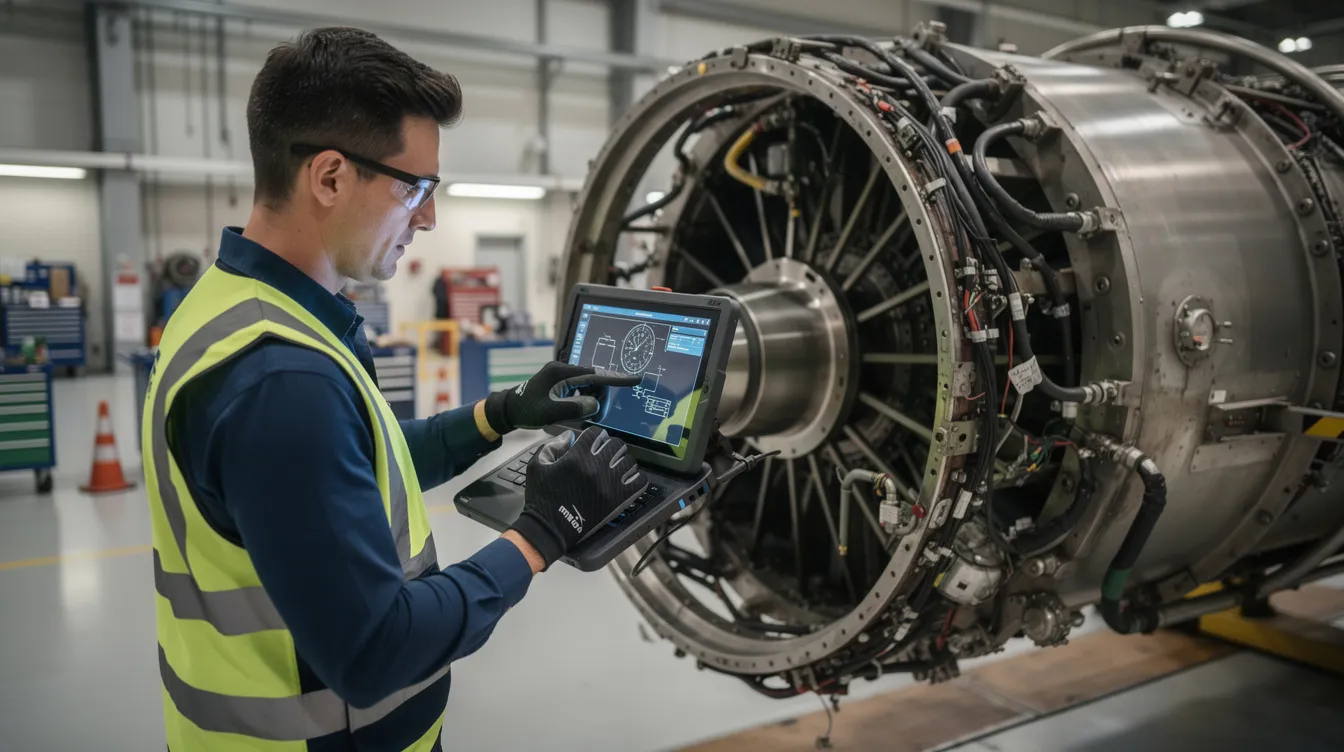
    An aerospace technician is using a tablet device to access digital work instructions while assembling an aircraft in a manufacturing facility. The digital transformation in aerospace and defense manufacturing enhances productivity and quality by providing real-time data and visual aids on the factory floor.

    Connect981 addresses these capabilities specifically for aerospace environments:

    • Embedded digital travelers showing routing and status, tied to each work order and serial number
    • Revision control and approval workflows ensuring only released instructions reach the shop floor
    • Part-level and serial-level traceability recording which operator performed which step, when, with what result
    • Integrated defect logging and nonconformance capture directly from the instruction screen
    • Support for final assembly lines, composite layup rooms, engine MRO cells, avionics repair benches, and supplier facilities
    • Connection to iot devices and torque tools for automatic data collection
    • Visual content including annotated drawings, 3D views, and photos from actual stations

    The glossary terms that recur throughout aerospace digital work instruction systems have specific meanings in practice. A digital traveler is the persistent record of a work order’s journey through manufacturing, holding routing information and collecting data at each operation. Revision control manages multiple versions of instructions, enforcing draft versus released states and documenting approvals. Manufacturing instructions are the procedural documents specifying how products should be manufactured. Process documentation is the broad category encompassing all technical guidance.

    How Digital Work Instructions Reduce Errors and Standardize Work

    Aerospace realities make error reduction essential. Escape defects can ground entire fleets. Concession costs run into millions. Flight safety incidents trigger regulatory scrutiny and program delays. Customer penalties for quality failures compound financial pressure on margins already stretched thin.

    Digital work instructions reduce errors through multiple mechanisms:

    • Guided step sequencing: Operators follow a defined sequence that prevents out-of-order execution. The system blocks progression until current steps are verified complete.
    • Required data entry: Certain fields cannot be left blank. Measurements, observations, and confirmations must be recorded before advancement.
    • Automatic validation: Tolerance checks compare recorded values against spec limits. Out-of-range entries are flagged immediately, before the operator moves on.
    • Tool verification: Connected torque tools, vision systems, and calibrated instruments auto-capture values and confirm correct tool usage.
    • Stop conditions: The system verifies prerequisites before allowing progression. If training records are missing or a previous step requires rework confirmation, execution is blocked.

    Results from aerospace implementations demonstrate the impact. Error rates dropped from 0.12% to zero. Scrap and rework reduced by 64%. Training time for new workers decreased by 50%. First time quality improved because defects were prevented rather than detected after the fact.

    Specific aerospace examples illustrate how this works in practice. Fuselage sections require hundreds of fasteners. Digital instructions can highlight each fastener location on a 3D model, require confirmation of each installation, and block completion until all positions are verified. Composite layup procedures demand precise fiber orientation. Digital systems track each ply, verify orientation, and log cure cycle parameters automatically from connected oven controllers. C-check and D-check MRO events involve hundreds of inspection steps. Digital instructions require evidence for each inspection, whether photos, measurements, or borescope images, ensuring nothing is marked complete without actual execution.

    Integration with inspection and measurement devices eliminates transcription errors. Real time data flows from torque wrenches, digital calipers, CMMs, and borescopes directly into the instruction system. Values are validated against tolerance bands instantly. This creates audit trails that prove not just what was recorded, but what actually happened.

    Standard work becomes enforceable across shifts and factories. Every operator at every site follows the same sequence, uses the same tools, and captures data in the same format. Multi-language and multi-unit variants operate under a single master revision. When instructions are updated, the update is instantly available everywhere. This standardization prevents the procedural drift that accumulates when frontline workers at different locations develop local variations.

    Supporting Compliance: AS9100, FAA/EASA, ITAR, and NADCAP

    Digital work instructions in aerospace are not primarily efficiency tools. They are compliance enablers that encode regulatory requirements and create audit ready records automatically. The documentation demands of aerospace and defense manufacturing make digital systems essential rather than optional.

    Core compliance themes addressed by digital work instructions:

    • AS9100: Clause 8.5.1 mandates controlled conditions for work execution. Digital systems prove control by maintaining revision history, tracking which instructions were used for which serial numbers, and linking execution to operator training and qualification records. Records retention becomes automatic rather than a manual archival project.
    • FAA/EASA: Maintenance documentation requirements demand traceable sign-offs tied to specific technicians and timestamps. Digital instructions capture exactly who performed each step, when, with what result. The complete maintenance history for an aircraft or engine becomes immediately accessible rather than scattered across filing cabinets.
    • NADCAP: Special processes like heat treat, non-destructive testing, and composite curing require parameter capture at the point of execution. Digital systems connected to oven controllers, NDT equipment, and cure monitoring systems log data in real time. The gap between process execution and parameter recording that exists in manual systems is eliminated.
    • ITAR: Defense programs require controlled access, data residency compliance, and role-based permissions that paper cannot provide. FedRAMP-ready cloud deployment or on-premises installation addresses these requirements. Access can be restricted to authorized personnel, with complete audit trails of who viewed or modified instructions.

    Connect981 maintains full audit trails covering who changed what instruction, when changes were approved, where instructions were executed, and which serial numbers were affected. Digital signatures tied to specific operators and timestamps replace handwritten initials that cannot be verified. Mandatory checklists ensure required steps are completed before progression. Automated escalation triggers when required approvals are skipped or when tolerance limits are exceeded.

    Maintaining compliance becomes an output of normal operations rather than a separate documentation exercise. Quality standards are encoded into the instruction workflow itself.

    Integration with ERP, MES, PLM, QMS, and Supplier Systems

    Digital work instructions function as the execution layer that sits on top of existing enterprise systems rather than replacing them. The goal is not to rip out ERP or MES but to create a connected layer that translates high-level work orders into guided shop floor execution and captures granular data for quality and compliance.

    Integration architecture for aerospace operations:

    • ERP sends work orders, part numbers, and due dates. As operators execute work, status updates flow back to ERP for accurate work-in-progress visibility.
    • PLM provides CAD drawings, BOMs, and engineering change data. Instructions reference the latest design, and when changes are issued, affected instructions are flagged for review.
    • MES or legacy systems track high-level routing while Connect981 manages detailed operator steps. The MES dispatches work to a work center; the digital instruction system guides what happens at that center.
    • QMS handles nonconformance workflows and CAPAs initiated directly from the instruction screen. When an operator discovers a defect, a nonconformance record is created automatically with all relevant context attached.

    Digital travelers pull and push data to these systems, creating a single consistent history per serial number. The digital thread connects design, manufacturing, and quality data into a traceable record that follows each part through its lifecycle.

    Multi-tier supplier integration extends visibility across the supply chain. Suppliers receive controlled access to work instructions, specifications, and change notifications through secure portals. As suppliers complete work, data returns to the OEM automatically. This visibility enables early defect detection and ensures supplier-manufactured parts meet the same quality standards as internal production.

    Real-time reporting becomes possible when manufacturing operations data flows from instruction execution. Production dashboards show WIP, bottlenecks, and quality trends without requiring manual data collection. Cycle time analysis, defect correlation, and operator performance tracking emerge from the same data captured during normal work.

    Digital Work Instructions Across Aerospace Use Cases

    Digital work instructions apply across the entire aerospace lifecycle, from prototype builds through rate production and into MRO and retrofit programs. The specific requirements vary, but the core need for controlled, traceable execution remains constant.

    Key aerospace scenarios:

    • New program industrialization: Early flight-test builds require rapid instruction updates as process issues are discovered. Digital systems enable same-day revisions with complete traceability of which serial numbers were built under which instruction version. A/B testing of different approaches becomes possible, with data showing which methods produce better outcomes.
    • Rate increases: Production ramps from 10 units per month to 40 units per month demand standardization across multiple assembly lines and sites. Digital instructions ensure every operator follows the same procedure regardless of location. New hires ramp faster because guided instructions reduce dependence on tribal knowledge and expert knowledge transfer.
    • Defense programs: Configuration control across multiple blocks (Block 1, Block 2, Block 3) requires instructions tied to specific configurations. Long service lives of 40 or more years demand documentation systems that can maintain records indefinitely. ITAR compliance requires controlled access that paper cannot enforce.
    • MRO and heavy checks: C-checks and D-checks involve hundreds of inspection and maintenance steps. Digital routing and instructions create complete maintenance histories tied to aircraft serial numbers. If a defect is discovered in service, the MRO work can be reviewed immediately to determine if the issue existed before maintenance or resulted from it.
    • Supplier manufacturing: Tier 1 and Tier 2 suppliers receive OEM-provided instructions to ensure consistency. Digital delivery with traceable completion data replaces paper packages sent via purchase order. The OEM gains visibility into supplier execution without requiring on-site audits for every operation.

    Connect981 adapts to mixed-model lines and complex options including customer-specific modifications, service bulletins, and retrofit kits. Instructions can be configured by variant, with the system automatically determining which version applies based on work order configuration.

    Designing Effective Aerospace Digital Work Instructions

    Manufacturing engineers and process owners responsible for authoring instructions need practical guidance for creating effective digital work instructions that operators can actually follow.

    Best practices for aerospace instruction design:

    • Start from validated templates tailored to aerospace tasks. Assembly, test, inspection, and rework operations each have common structures that can be standardized and then customized for specific applications.
    • Use clear, operator-focused language rather than pure engineering jargon. Reference spec IDs and drawing callouts accurately, but write for the person executing the work rather than the engineer who designed the process.
    • Include visual aids. Annotated drawings, 3D views, and photos from actual stations reduce ambiguity, especially for complex assemblies and harness routing. Videos demonstrating correct technique can accelerate training for new employees.
    • Build in checks and balances. Required data fields prevent progression without complete information. Automatic tolerance checks validate measurements against spec limits. Stop conditions block advancement when prerequisites are not met.
    • Consider training needs. Design instructions that can serve as on-the-job training content for new operators and cross-training programs. Include explanations of why steps matter, not just what to do.
    • Structure for multi-site deployment. Localizations for language, metric versus imperial units, and local tooling should be variants under one master process. When the master is updated, all variants update simultaneously.

    Connect981 offers drag-and-drop templates and zero-code workflow tools so process owners can design and deploy instructions without heavy IT involvement. This enables rapid iteration during early production when instructions change frequently and eliminates the bottleneck of waiting for IT resources to implement updates.

    Change Management, Revision Control, and Digital Travelers

    Unmanaged change is a primary source of defects in aerospace manufacturing. Engineering changes are frequent, especially during early production. When instructions change but operators use old versions, mixed lots and traceability gaps result. Paper systems cannot reliably control which version is current across distributed operations.

    Proper revision control in digital systems operates through defined states and workflows:

    • Draft vs. released states: Engineers work on draft revisions without affecting the shop floor. Only released revisions are visible to operators, preventing half-finished instructions from reaching production.
    • Approval workflows: Before release, revisions require approval from manufacturing engineering, quality, and sometimes customer representatives. Approval records are timestamped and archived.
    • Automatic archival and comparison: Every revision is stored with full metadata. Comparison tools show exactly what changed between versions.

    Digital travelers in Connect981 are always tied to the correct revision of work instructions for a given work order and serial number. The system enforces this binding automatically.

    Practical mechanisms for managing change:

    • Operators cannot access obsolete documents. The system presents only the current released revision for each work order.
    • Emergency deviations and temporary revisions can be implemented with controlled scope and automatic rollback when the deviation expires.
    • Complete records show which serial numbers were built under each revision. If a defect is traced to a procedural issue, affected units can be identified immediately for inspection or retrofit.
    • Version control prevents the scenario where an auditor asks which procedure was in effect for a specific build and no one can answer definitively.

    Data, Analytics, and Continuous Improvement from Instruction Execution

    Because every step of a digital work instruction is logged with timestamps, operator IDs, and measured values, the system generates granular data that powers continuous improvement and predictive quality. This data exists as a byproduct of normal work rather than requiring separate data collection efforts.

    Analytics capabilities from instruction execution data:

    • Step-level cycle times identify bottlenecks on assembly lines or MRO cells. If one step consistently takes longer than expected, investigation can reveal tooling issues, training gaps, or procedural inefficiencies.
    • Defect correlation connects quality issues to specific steps, tools, shifts, or operators. If a particular assembly step shows elevated defect rates, root cause analysis can focus there. If defects spike during a specific shift, workforce or supervision issues might be the cause.
    • Rework rate tracking by process, program, or supplier prioritizes improvement projects. Increasing rework rates signal growing problems before they become critical.
    • Operator performance monitoring compares execution across operators to identify training needs, skill certifications, and optimal task assignments. New hires can be tracked over time to measure ramp-up effectiveness and accelerate training programs.
    • Tool usage patterns reveal when equipment is drifting out of calibration or approaching end of life.

    Connect981 includes real-time dashboards and AI-assisted root cause analysis focused on aerospace operations data. Artificial intelligence can identify patterns that would take humans hours to spot, accelerating problem resolution.

    These insights directly support audit readiness. When an OEM auditor or FAA inspector asks for evidence that a specific procedure was followed correctly, reports can be generated in minutes rather than weeks. The execution history provides complete, timestamped documentation of every action.

    Analytics tie back to strategic initiatives like rate readiness and smart factory programs. The ability to continuously improve based on actual execution data rather than assumptions transforms digital work instructions from documentation tools into operational intelligence platforms.

    Implementing Digital Work Instructions in an Existing Aerospace Environment

    Implementing digital work instructions in established aerospace operations requires a practical approach that works alongside existing systems rather than forcing a complete infrastructure replacement.

    Phased adoption roadmap:

    • Assessment: Map current travelers, instructions, and compliance requirements across key programs and sites. Identify where paper processes create the most friction and where compliance gaps present the greatest risk.
    • Pilot: Choose a representative line or MRO cell to prove value and refine templates. A complex assembly operation or engine module works well because it exercises the full range of instruction capabilities without putting entire programs at risk.
    • Standardization: Define global templates for common process types and governance rules for authors. Establish who can create and approve instructions, what review processes are required, and how revisions flow to the shop floor.
    • Integration: Connect to ERP, PLM, MES, and QMS systems with focus on a few high-value data flows first. Work order dispatch and status updates typically provide immediate value. Broader integration can follow as the deployment matures.
    • Scale: Roll out to additional lines, sites, and suppliers using lessons learned and standardized training materials. The pilot team becomes champions who can support broader adoption.

    Involving manufacturing engineers, quality, IT, and frontline operators from the outset ensures the system is designed for actual use cases and builds buy-in for adoption. Operators who see the system reduce their daily frustrations become advocates rather than resistors.

    Connect981 is designed to run alongside existing ERP and MES with low IT overhead. The goal is deployment in months rather than the multi-year cycles associated with full system replacements. Digital transformation happens incrementally, proving value at each stage before expanding scope.

    A manufacturing team is collaborating around a digital display that showcases digital work instructions, enhancing their manufacturing operations. This setup emphasizes the importance of visual aids and real-time data in aerospace and defense manufacturing, promoting continuous improvement and reducing errors on the factory floor.

    How Connect981 Supports Digital Work Instructions for Aerospace Teams

    Connect981 acts as a unified operations layer specifically tuned for aerospace and MRO digital work instructions. The platform addresses the unique requirements of aerospace manufacturing, from serial number traceability to configuration control to the documentation structures required by AS9100 and FAA environments.

    Key capabilities that differentiate Connect981 for aerospace operations:

    • Aerospace-native data model: Serial number focus, configuration control, and documentation structures built for aerospace compliance rather than adapted from generic manufacturing systems.
    • Zero and low-code workflow builder: Manufacturing engineers can build and maintain instructions without heavy IT projects. Drag-and-drop templates and visual workflow builders eliminate paper and enable rapid deployment.
    • Cross-factory and cross-supplier visibility: One environment for OEM plants, MRO shops, and external suppliers with appropriate access controls.
    • Integrated quality and traceability: Defect capture, inspection checklists, and full audit trails tied to each instruction step create audit readiness as a byproduct of normal operations.
    • Fast deployment: Pilot to multi-line rollout in months rather than multi-year MES replacement cycles.
    • Mobile devices support: Operators access instructions on tablets and workstations appropriate for their work environment.
    • Connected tool integration: Torque tools, iot devices, and measurement equipment integrate directly for automatic data capture.

    The platform saves time by eliminating manual documentation, paper reconciliation, and the compliance scramble that precedes audits. Efficiency gains compound across operations as standardized processes replace scattered tribal knowledge.

    Next Steps and How to Get Started

    Conclusion digital work instructions: the shift from paper based work instructions to connected digital systems is foundational to consistent, compliant aerospace manufacturing. Error reduction, standardized work, and audit ready documentation emerge naturally when instructions guide operators through validated procedures and capture data at the point of execution. The technology exists today to eliminate paper and transform how aerospace and defense manufacturers control factory floor operations.

    For manufacturing engineers, operations leaders, and quality managers evaluating this transition, start by identifying one pilot area where digital work instructions would provide immediate value. Look for processes with high rework rates, compliance pressure, or reliance on tribal knowledge that does not scale.

    Related content for deeper exploration:

    • Digital travelers and routing management
    • Work instruction version control and approval workflows
    • Operator guidance systems and error proofing
    • MES integration and connected shopfloor architecture
    • Reducing human error through digital guidance

    Request a demo of the Connect981 platform to see how these capabilities apply to your specific programs. Demos can be tailored to commercial, defense, or MRO operations and your existing system landscape. The path from paper to connected digital work instructions is shorter than most organizations expect when the platform is designed specifically for aerospace realities.

  • What is the highest paid job in supply chain?

    There is no single “highest paid” supply chain job across all companies. Pay at the top end is driven less by the job title label and more by scope, P&L impact, regulatory exposure, and scarcity of expertise.

    Roles that typically sit at the top of the pay range

    In industrial, regulated environments, the highest compensation is usually found in roles like:

    • Chief Supply Chain Officer (CSCO) or EVP/VP Supply Chain with global scope and direct influence on P&L, inventory, working capital, and service levels.
    • Head of Operations / COO with supply chain accountability, where manufacturing, logistics, and supplier management sit under one executive.
    • VP/Head of Procurement or Strategic Sourcing in materials-intensive businesses (aerospace, pharma, medical devices, semiconductors, energy) where supplier risk, long lead equipment, and regulatory exposure are high.
    • VP/Head of Planning & Logistics in organizations where supply chain reliability is mission critical (e.g., aftermarket support, defense programs, high-mix low-volume with contractual penalties).

    At the executive level, total compensation is often dominated by bonuses and long-term incentives tied to inventory turns, service levels, cost of goods, and program milestones. In some firms, the COO with strong supply chain scope will earn more than a CSCO in another firm; title alone does not guarantee the pay band.

    Highly paid non-C-suite supply chain roles

    Below the C-suite, some roles can reach very high compensation when tied to high-consequence risk or scarce skills:

    • Senior Director / Director of Supply Chain in a major site or business unit with full responsibility for planning, materials, logistics, and supplier performance.
    • Director of Supplier Quality & Development in aerospace, defense, or life sciences, where supplier issues directly affect certification, recalls, or contractual penalties.
    • Director of Integrated Business Planning (IBP/S&OP) when they orchestrate demand, supply, and financial planning across multiple plants and regions.
    • Director of Logistics & Network Design for complex global networks with trade compliance, cold chain, or hazardous materials constraints.
    • Technical specialist roles (e.g., senior supply chain architect, network optimization expert, advanced planning systems lead) embedded in operations or IT, where deep systems and data integration skills intersect with regulated operations.

    These roles often command high pay because they sit at the intersection of supply continuity, regulatory risk, and major capital or operating costs.

    Key factors that drive the top end of pay

    Compensation at the top end of supply chain roles depends heavily on context:

    • Industry and regulatory burden: Aerospace, defense, pharma, and medical devices often pay more than light manufacturing or distribution because supply failures have higher legal, safety, and contractual exposure.
    • Scope and scale: Global multi-plant networks, complex supplier ecosystems, and high-mix low-volume manufacturing typically pay more than a single local site.
    • P&L and balance sheet impact: Roles directly accountable for inventory, working capital, material cost, logistics spend, and on-time delivery trend higher than “advisory” or narrow functional roles.
    • Exposure to critical programs: Program-critical roles in long-lifecycle equipment (airframes, turbines, therapeutics, fabs) are often paid at a premium because delays or shortages cascade into major financial and contractual impact.
    • Brownfield systems competence: In many plants, leaders who can improve performance without full system replacement, and who understand MES/ERP/QMS/MRP coexistence, are more valuable than those proposing greenfield overhauls with high validation and downtime risk.
    • Talent scarcity: Deep knowledge of export controls, regulated cold chain, advanced planning engines, or multi-tier supplier risk often pushes pay higher.

    Why there is no universal “top job”

    Across regulated, long-lifecycle industries, the highest paid supply chain role could be a CSCO in one company, a COO with integrated supply chain in another, or a highly specialized procurement or logistics executive in a third. Structural differences matter:

    • Ownership: Private equity ownership may drive aggressive incentives tied to working capital and cost reduction. State-owned or family-owned firms may have different bands.
    • Geography: Pay levels vary significantly between regions and even between major hubs within a region.
    • Org design: Some companies centralize planning and procurement; others push responsibility to business units or plants. Pay follows where accountability actually sits, not just title labels.

    As a result, there is no single job title that is always the highest paid in supply chain. The most consistently high-compensation category is senior leadership with end-to-end supply chain accountability and direct impact on financial and regulatory risk.

    Implications if you are planning your career

    If you are deciding where to specialize, focusing solely on the theoretically highest paid job is usually less practical than building toward roles with broad accountability and scarce skills:

    • Seek experience where planning, procurement, logistics, and manufacturing operations intersect, not just one narrow function.
    • Develop fluency in MES/ERP/MRP and QMS integration, and understand change control, validation, and traceability requirements.
    • Take on roles with real accountability for service levels, inventory, and supplier performance, not just analysis or reporting.
    • In regulated environments, build credibility around risk management, audit readiness, and compliance-aligned process improvement.

    Over time, those capabilities are what typically open the door to the better-paid senior director, VP, and C-level supply chain roles.

  • What is the ISA-88 standard?

    ISA-88, often written as S88, is an international standard for batch process control. It provides a common set of models and terminology for describing batch processes, equipment, and control logic so that engineering, operations, quality, and IT can structure and automate batch manufacturing in a consistent way.

    What ISA-88 actually defines

    ISA-88 is not a software product or certificate. It is a set of models and guidelines that you can apply to control systems, MES, and procedures. The core elements are:

    • Physical model: A hierarchy for structuring equipment (enterprise, site, area, process cell, unit, equipment module, control module). This provides a consistent way to describe skids, reactors, packaging lines, and utilities.
    • Procedural model: A hierarchy for defining how batches are run (procedure, unit procedure, operation, phase). This separates “what you want to do” from “what the hardware is.”
    • Process model: A way to describe the process itself, independent of implementation (process, process stage, process operation, process action).
    • Recipe models: Structures for master, site, and control recipes, including parameters, materials, and formulae, with clear separation between product definition and equipment-specific execution.
    • Terminology and data concepts: Common language for batches, campaigns, equipment states, and recipe elements that can be mapped into DCS, batch servers, and MES.

    Why ISA-88 matters in regulated, brownfield environments

    In regulated and long-lifecycle plants, ISA-88 is mainly valuable because it enforces structure and traceability across systems and over time:

    • Traceability and impact analysis: Having a clear mapping from recipes and procedures down to phases and control modules makes it easier to assess the impact of control changes on validated processes and documentation.
    • Separation of concerns: By separating product definition, procedures, and equipment, you can change one layer (for example, add a new unit) with less disruption to others, subject to revalidation.
    • Vendor and system coexistence: The models provide a neutral way to describe batch logic across different DCS, batch engines, and MES vendors, which helps when integrating or upgrading individual components rather than replacing everything.
    • Documentation alignment: Batch records, SOPs, and functional specifications can be written in terms of the same objects (procedure, operation, phase), supporting clearer validation and change control.

    What ISA-88 does not do

    There are important limitations:

    • No compliance guarantee: Adopting ISA-88 terminology or models does not guarantee regulatory compliance, successful audits, or approval of any specific product or system.
    • No mandated architecture: ISA-88 does not force a particular system architecture or vendor. Different plants and control system vendors implement S88 concepts differently, with varying coverage.
    • No automatic interoperability: Two systems that both claim ISA-88 alignment may still require custom integration and careful mapping of models and data structures.
    • No safety or legal guidance: ISA-88 is focused on control structures and batch models, not on process safety, worker safety, or legal obligations.

    How ISA-88 fits with existing systems

    In most plants, ISA-88 is applied into a brownfield landscape rather than a clean-sheet design. Typical patterns include:

    • Layered on existing DCS / PLC logic: Many sites progressively refactor control code into phases and equipment modules that align with ISA-88 during normal upgrade cycles, rather than rewriting everything at once.
    • Aligned with MES batch functionality: MES batch or electronic batch record modules often use S88-like structures for recipes and execution. The practical benefit depends on how accurately the MES layer is mapped to the actual control modules and field equipment.
    • Incremental adoption: Plants may adopt only parts of the standard (for example, physical and procedural models) where they add clear value, and leave legacy sections of the plant on older structures until a major retrofit is justified.
    • Long lifecycle constraints: Full replacement of existing batch systems just to achieve “pure” ISA-88 compliance often fails in practice because of validation cost, downtime risk, and integration complexity. Most organizations instead map legacy models into ISA-88 concepts as far as is practical.

    Key tradeoffs and implementation considerations

    Using ISA-88 effectively involves several tradeoffs:

    • Standardization vs flexibility: A strict ISA-88 model improves consistency and maintainability but can feel rigid for edge-case processes or unusual equipment. Over-standardization can slow changes in high-mix environments.
    • Refactoring cost vs long-term maintainability: Refactoring legacy code into ISA-88 structures can be expensive and may introduce risk if not done carefully. The return is typically realized in easier modifications, clearer validation evidence, and better integration over the equipment lifecycle.
    • Model purity vs operations reality: Some facilities intentionally deviate from “textbook” S88 to handle specific regulatory or operational constraints. The important point is clear documentation of the chosen model and its rationale, not theoretical purity.
    • Validation and change control: Any restructuring of batch logic to align with ISA-88 must pass through normal change control, testing, and validation. The standard can support clearer test plans and traceability, but it does not reduce the need for them.

    In summary, ISA-88 is a foundational standard for batch process modeling and control. Its value in regulated, long-lifecycle manufacturing comes from the structure and common language it provides, not from any guarantee of compliance or automatic interoperability. Real benefits depend on disciplined implementation, careful integration with existing systems, and robust change control.

  • What are the 4 types of CTI?

    In the context of industrial and regulated environments, the “4 types of CTI” normally refers to the four layers of Cyber Threat Intelligence that organizations consume and produce:

    1. Strategic CTI

    Purpose: Support executive and risk-level decisions.

    Typical content:

    • High-level threat landscape for your industry (e.g., targeted ransomware on manufacturing, supply chain attacks on PLC vendors).
    • Adversary motives, capabilities, and trends affecting plants and suppliers.
    • Regulatory and geopolitical factors that change cyber risk for operations (for example export controls impact, OT-focused regulations).

    Primary users: Senior leadership, risk officers, CISOs, and OT governance boards.

    Dependencies and constraints: Strategic CTI only becomes useful when it is tied to your actual asset base, process criticality, and regulatory obligations. Generic reports that do not reflect your brownfield stack (legacy DCS, mixed MES/ERP, vendor-locked PLCs) tend to be accurate but operationally irrelevant.

    2. Operational CTI

    Purpose: Guide security operations and incident response planning.

    Typical content:

    • Campaign summaries for specific threat groups targeting industrial or critical infrastructure.
    • Observed TTPs (tactics, techniques, and procedures) mapped to frameworks like MITRE ATT&CK for ICS or enterprise.
    • Playbook-level guidance on how threats move through IT and OT networks, including pivot paths into MES, historians, engineering workstations, and safety systems.

    Primary users: SOC analysts, incident response teams, and OT security engineers.

    Dependencies and constraints: To apply operational CTI reliably, you need an accurate, maintained asset inventory, current network diagrams, and documented interfaces (MES, ERP, QMS, remote vendor access). Without this, it is hard to map threat scenarios to real attack paths or to design practical containment steps that respect validation and uptime constraints.

    3. Tactical CTI

    Purpose: Inform defensive design and hardening decisions.

    Typical content:

    • Details of specific techniques used against industrial environments (e.g., abuse of engineering tools, backup manipulation, recipe theft, or misuse of remote maintenance channels).
    • Recommended detection and mitigation controls at the control system, network, and identity layers.
    • Guidance on zoning/segmentation, remote access patterns, and monitoring of key OT assets.

    Primary users: OT/IT security architects, control engineers working with security, and infrastructure teams.

    Dependencies and constraints: Tactical CTI must be adapted to your specific control platforms, vendor firmware, and existing network architecture. In regulated plants, changes implied by tactical CTI (such as new monitoring agents or modified firewall rules) often trigger change control, regression testing, and sometimes re-validation. Full “rip-and-replace” re-architecture driven purely by tactical CTI usually fails because of qualification burden, downtime risk, and the long lifecycle of automation assets.

    4. Technical CTI

    Purpose: Feed automated defenses and investigations with concrete indicators.

    Typical content:

    • Indicators of compromise (IOCs): IPs, domains, file hashes, URLs, certificate fingerprints.
    • Signatures and detection rules (e.g., YARA, Suricata/Snort rules, SIEM correlation rules).
    • Artifacts from malware or toolsets used in campaigns targeting industrial environments.

    Primary users: SOC engineers, detection engineers, and security tool administrators.

    Dependencies and constraints: Technical CTI only has impact if your existing tools (firewalls, OT monitoring appliances, SIEM, EDR, log collectors) can ingest and act on the indicators without disrupting operations. In brownfield OT networks, many devices cannot run modern agents or support deep inspection, and downtime windows are tightly controlled. Indicator-based blocking must therefore be tuned carefully to avoid process impact and unintended validation implications.

    How these CTI types fit industrial and regulated environments

    In regulated and long-lifecycle manufacturing environments, all four CTI types need to be integrated with existing processes and systems rather than assumed to drive wholesale replacement:

    • Strategic & operational CTI should inform your risk register, business continuity planning, and vendor management, not just IT roadmaps.
    • Tactical CTI should be implemented through controlled, incremental hardening projects that respect change control, validation, and qualification needs for MES, PLCs, SCADA, and supporting IT systems.
    • Technical CTI must be filtered and prioritized; trying to apply every feed often exceeds SOC and OT team capacity, and can introduce false positives that operators will eventually ignore.

    Across all four types, the value of CTI depends heavily on integration quality, data readiness (asset inventory, topology, baselines), and the maturity of your incident response and change-control processes. It is not a guarantee of security or compliance, but it can materially improve decision making at each level when aligned with plant reality.

  • What is the scope in ISO 27001?

    In ISO 27001, the scope is the formal, written definition of what parts of your organization the Information Security Management System (ISMS) applies to. It sets the physical, organizational, and technical boundaries within which you manage information security risks according to the standard.

    What the ISO 27001 scope must cover

    The scope statement should clearly identify:

    • Organizational boundaries: Business units, legal entities, and functions covered (for example: corporate IT only, or corporate IT plus selected plants).
    • Physical locations: Sites, offices, data centers, and plants that are in scope, including remote or hosted environments.
    • Information and processes: Types of information and the processes that create, process, store, or transmit it (for example: production planning, quality records, engineering data, supplier data).
    • Systems and technologies: Applications, infrastructure, OT/ICS, and cloud services governed by the ISMS.
    • Interfaces and dependencies: How in-scope systems interact with out-of-scope systems, partners, and suppliers.

    The scope must be consistent with your context, risk assessment, and interested parties. ISO 27001 does not dictate a single “correct” scope, but the scope cannot be defined in a way that hides or ignores significant information security risks.

    How scope works in complex manufacturing environments

    In regulated, brownfield operations, the scope decision has practical constraints:

    • Legacy and OT systems: Many plants have SCADA, PLCs, and legacy MES that are difficult to patch or monitor. You must explicitly decide whether these are in or out of scope, and document the rationale and compensating controls if excluded.
    • Mixed vendor stacks: ERP, MES, PLM, QMS, and data historians from multiple vendors typically span IT and OT. If you include one layer in scope (for example, MES), interfaces to out-of-scope layers must still be risk-assessed and controlled.
    • Downtime and change windows: A wider scope can increase the operational impact of required controls (for example, change control for firewall rules on production cells), so scope must be realistic about what can be governed without jeopardizing uptime.
    • Long lifecycle equipment: Some assets will not support modern controls. The scope statement should acknowledge these limitations and point to risk acceptance, isolation, or layered controls instead of implying full technical conformity.

    Typical scope patterns

    In practice, organizations in industrial and regulated environments often choose one of these patterns:

    • Corporate IT only: The ISMS covers corporate networks, business applications, and central services. OT and shop-floor systems are explicitly out of scope, but are recognized as interfaces or dependencies.
    • Selected plants or value streams: The ISMS covers specific sites, lines, or programs, usually where regulatory or customer pressure is highest, with a plan to expand over time.
    • Integrated IT/OT scope: The ISMS covers both corporate IT and defined OT environments (for example, all lines producing a certain regulated product), with explicit recognition of legacy constraints and tailored controls.

    A full “everything, everywhere” scope can be attractive on paper but frequently fails in long-lifecycle environments because it becomes too costly to implement, validate, and maintain controls across all assets and sites, especially where downtime and change control are heavily constrained.

    Key tradeoffs when defining ISO 27001 scope

    • Coverage vs. implementability: A broad scope provides better risk coverage but is harder to operationalize and maintain, especially across multiple plants and vendors.
    • IT vs. OT inclusion: Including OT increases relevance to real production risk, but also increases complexity, integration challenges, and the need for OT-specific controls and competencies.
    • Regulatory & customer expectations: A narrow scope may meet the letter of ISO 27001 but may not satisfy aerospace, defense, or pharma customers if critical production or technical data environments are excluded without a clear rationale.
    • Evidence and traceability burden: A wider scope multiplies the volume of assets, changes, and records you must control and evidence. In environments with strict validation and change control, this can be a major operational load.

    Practical considerations for defining scope

    When you draft your ISO 27001 scope in an industrial context:

    • Base it on a documented understanding of your business processes and information flows, not just org charts.
    • Describe boundaries in terms of processes, sites, and systems so it is clear what is included and excluded.
    • Identify critical interfaces to other systems and partners, and show how those risks are addressed even if the external systems are out of scope.
    • Ensure the scope is stable enough to be maintained over the life of your assets, but flexible enough to extend as you modernize.
    • Keep the scope statement aligned with your risk assessment and Statement of Applicability so auditors and customers can trace your logic.

    The result should be a scope that is realistic for your brownfield environment, transparent about constraints, and supportable over time without implying guarantees you cannot operationally sustain.

  • First Article Inspection Software: Stand-Alone FAIR Tools vs Connected Aerospace Execution Platforms

    First Article Inspection Software: Stand-Alone FAIR Tools vs Connected Aerospace Execution Platforms

    Overview: How This Guide Helps You Choose the Right FAI Software

    First article inspection software automates the verification process to ensure a manufacturing line can produce parts that meet engineering specifications before full production begins. In aerospace and MRO, that decision affects release timing, supplier corrections, audit readiness, and whether article inspection reports can be trusted under pressure.

    This guide compares stand-alone fai software with connected execution platforms like Connect981 that link quality, operations, and system data. The question is practical: when is a basic FAIR tool enough, and when do ERP, MES, QMS, and PLM integrations become critical?

    First article inspection, often shortened to first article inspection fai in buyer documents, depends on a defensible ballooned drawing, clear characteristic accountability, and a compatibility evaluation against the engineering drawing, CAD model, and specification requirements. The article inspection process must show that every design characteristic is properly understood, measured, and recorded.

    Connect981 is a B2B SaaS platform for digital industrial operations, focusing on aerospace manufacturing and MRO workflows. It is not just article inspection software; it connects ERP, MES, supplier data, documentation, and work execution into a unified operations layer.

    Fast Comparison: Stand-Alone FAI Tools vs Connected Execution Platforms

    Use this as a quick buyer snapshot before the detailed examination.

    Stand-alone FAI / FAIR tools

    Connected execution platforms (e.g., Connect981)

    Best for ballooning, form creation, and first article inspection reports.

    Best for end-to-end execution, quality control, routing, and traceability.

    Usually uses manual uploads of PDFs, CAD exports, and measured values.

    Pulls data from ERP, MES, QMS, PLM, supplier portals, and shopfloor execution.

    Traceability often ends at the fai report or shared folder.

    Links FAI, work order, serial number, lot, defect, concession, and material certifications.

    Supplier collaboration is usually email, upload, or net inspect style portal exchange.

    Supports real time collaboration, supplier buy-off, field level comments, and shared status.

    Works well for one site and limited production process change.

    Scales across factories, programs, suppliers, and MRO workflow management.

    Lower cost and faster setup.

    Higher value where compliance exposure, integration, and process control matter.

    Better choice for a few FAIs per month, single site, stable work.

    Better choice for dozens of FAIs, multi-site programs, AS9100/ITAR pressure, and tight OEM turnarounds.

    Many organizations start with stand-alone inspection software, then move to a connected platform when volume, risk, or customer quality requirements grow.

    First Article Inspection Basics: What FAIRs Need to Prove

    First Article Inspection (FAI) is a critical quality assurance process that ensures manufactured parts meet design specifications before full production begins, particularly in industries such as aerospace, automotive, and medical devices. It is also central to the aerospace industry, automotive industry, medical manufacturing, and defense industries where product safety and reliability depend on early proof of capability.

    The fai process involves a detailed examination of the first sample produced from a manufacturing run, known as the first article, and includes checking dimensions, materials, and features against design specifications. FAI is mandated by various industry standards, including AS9102 for aerospace, which requires comprehensive documentation and verification of production methods to ensure compliance and quality. The AS9102 specification, developed by the international aerospace quality group, outlines requirements for first article inspection in the aerospace industry, ensuring that all aspects of design, manufacturing, and inspection are verified and documented.

    An article inspection report documents dimensions, tooling, material specifications, testing processes, product accountability, number accountability, parts lists, routing, process certs, CMM outputs, and customer forms against the technical data package. The FAI report serves as a record for the company, addressing government regulations that require detailed documentation of production methods, tooling, material specifications, and testing processes.

    FAI is mandated as a purchase order requirement in the aerospace and defense industries, ensuring compliance with strict quality standards to prevent safety risks and costly corrective actions. Implementing FAI helps mitigate risks by identifying potential issues before mass production, thus preventing costly corrective actions and ensuring product safety and reliability.

    Example: before a 2025 supplier releases a machined bracket to full scale production, the inspection plan and fai plan should prove every balloon on the bubble drawing has inspection results, measured values, and proper documentation.

    What Stand-Alone First Article Inspection Software Does Well

    Stand-alone first article inspection software is usually a desktop or cloud tool focused on the ballooning process and standardized AS9102 or PPAP output. FAI software digitizes the creation of FAI reports (FAIRs), mandated by industries like aerospace (AS9102) and automotive (PPAP).

    The most effective FAI software options focus on automating drawing ballooning, extracting Geometric Dimensioning and Tolerancing (GD&T) data, and exporting standardized reports like AS9102 or PPAP. Automated Ballooning automatically identifies and numbers dimensions on 2D engineering drawings. Data Extraction in FAI software pulls nominal values, tolerances, and notes from CAD models or PDFs. Modern FAI software automates the extraction of geometric dimensioning and tolerancing (GD&T) characteristics directly from CAD drawings, significantly reducing manual data entry and errors.

    Typical functions include optical character recognition, GD&T capture, AS9102 Forms 1–3, ballooned drawings, limited CMM upload, and export to PDF, Excel, or portals. Digital Measurement Capture imports data directly from calipers, micrometers, and Coordinate Measuring Machines (CMM). Many tools can import cmm data from coordinate measuring machines, cmm software, and modern cmm technology.

    FAI software eliminates human error by removing manual typos when transferring complex dimensions to spreadsheets. It also accelerates the ballooning, measurement, and AS9102 reporting process, significantly reducing human error. FAI software reduces inspection time by cutting drawing ballooning and data entry time by up to 80%, and FAI software can reduce the time required for the First Article Inspection process by as much as 50%, streamlining this crucial process without sacrificing quality or dependability.

    A Tier-3 shop doing 5–10 FAIs per month for AS9102 and PPAP may use a low-cost tool to move from days to hours. Net-Inspect is widely utilized in the aerospace sector for cloud-based supplier collaboration and AS9102 compliance.

    An inspector is closely examining a machined aerospace component while surrounded by various measuring tools, emphasizing the importance of the first article inspection process in the aerospace industry. This detailed examination is crucial for ensuring compliance with specification requirements and maintaining quality assurance throughout the manufacturing process.

    Limits of Keeping FAI Software Disconnected

    Problems appear when first article inspections stay isolated from the quality assurance process and operations stack. FAIRs become static PDFs, weakly tied to work orders, serials, lots, nonconformance records, concessions, and fai data.

    Manual data entry creates transcription errors when teams retype part numbers, rev levels, tolerances, drawing notes, and product specifications from ERP or PLM. If the engineering drawing changes mid-program, a disconnected FAIR may still reference the wrong revision.

    Cross-site work adds more risk. Each plant or supplier may use different formats, different ballooned drawing conventions, and inconsistent characteristic accountability. In 2024, a multi-site aerospace supplier failed an OEM audit because FAIRs could not be tied reliably to work orders, lots, and concessions across three plants.

    Stand-alone tools rarely manage contract review, PO inspection requirements, supplier buy-off, or automatic alerts when a change notice affects an existing fai inspection.

    When a Connected Execution Platform Becomes Essential

    A connected execution platform unifies ERP, MES, QMS, PLM, supplier workflow, shopfloor execution, and quality checks, including FAI. The tipping points are clear: dozens of FAIs per month, multiple sites, complex assemblies, strict AS9100 or ITAR programs, frequent changes, and OEM portals with tight turnaround.

    FAI software catches defects early by validating production processes, tooling, and raw materials on the first run, decreasing scrap, rework, and waste. FAI software speeds up production by allowing faster FAI approval, enabling manufacturing lines to begin full production sooner. FAI software facilitates faster release to full-rate production by accelerating the First Article Inspection Report (FAIR) creation and approval process.

    Integration creates the digital thread. FAI software creates a secure, searchable digital thread of dimensional records and testing. FAI software improves traceability by storing digital records centrally for easy auditing and historical quality tracking. FAI software standardizes workflows by ensuring all inspectors follow the same verification procedures.

    In a 2025 MRO operation, a connected platform can trigger FAI automatically when a repair route or drawing for a flight-critical component changes, then tie the outcome to tail number, serial history, material certifications, and inspection results.

    How Connect981 Supports First Article Inspections End-to-End

    Connect981 embeds first article inspection into production and MRO execution rather than treating it as a disconnected app. FAI steps can sit inside digital work instructions, routing sheets, supplier workflows, quality checks, and defect logging.

    Connect981 can ingest drawings and specifications from PLM, sync part and BOM data from ERP, and anchor FAIRs to work orders and serials in MES or existing systems. This helps ensure accuracy when a design characteristic, lot, or supplier process changes.

    For quality assurance, Connect981 links characteristic accountability to actual measured values, defect records, balloon numbers, certifications, customer correspondence, and fai related documentation. Modern FAI software solutions allow for the electronic review and approval of inspection reports, facilitating quicker corrections and enhancing compliance in industries with stringent standards.

    Connect981 enables real-time reporting, dashboards, and predictive analytics for decision-making in manufacturing workflows. Connect981 supports zero and low-code workflow builder for rapid deployment in aerospace manufacturing environments.

    A technician stands beside an aircraft component in a maintenance bay, using a tablet to access first article inspection software for the inspection process. This scene highlights the critical role of quality assurance in the aerospace industry, ensuring that all specification requirements are met during the manufacturing process.

    Buyer Decision Criteria: Stand-Alone FAI Tool or Connected Platform?

    Use the criteria below with a quality manager, manufacturing engineering, supply chain, IT, program managers, technical professionals, and other technical professionals.

    Criterion

    Stand-alone fit

    Connected platform fit

    FAI volume

    Few per month

    Dozens per month

    Sites

    Single plant

    Multi-site standardization

    Assemblies

    Simple, stable parts

    Complex builds and MRO histories

    Compliance

    Limited customer exposure

    AS9100, AS9102 Rev C, NADCAP, ITAR, FAA, EASA

    System landscape

    Minimal integration need

    ERP, MES, QMS, PLM data continuity

    Supplier network

    Small, mature base

    Multi-tier supply chain

    IT capacity

    Quick win

    Hybrid or phased path

    Ask vendors: how are rev changes from engineering drawings handled; how is characteristic accountability maintained across re-inspections; what ERP/MES/QMS/PLM integrations exist; how is ITAR/CUI data protected; and how are electronically recorded approvals locked?

    High QA is a comprehensive, modular manufacturing quality suite that integrates FAI data into broader operations like Statistical Process Control (SPC) and Non-Conformance Reports (NCR). That category shows why buyers should evaluate whether FAI belongs alone or inside broader quality operations.

    Integration and Traceability: What to Verify Before You Buy

    For aerospace and defense, integration and digital traceability can matter as much as speed when selecting article inspection software. Verify part and lot data from ERP, latest drawings from PLM, nonconformance links in QMS, supplier portal status, and MES work order context.

    A strong digital thread ensures the article inspection report reflects the correct configuration, revision, manufacturing process, and process history for each first article. Digital tools enable the automation of GD&T extraction from CAD drawings, which populates structured audit records and enhances the efficiency of the FAI process.

    Compatibility evaluation should cover APIs, data models, CUI controls, legacy MES constraints, and whether the platform can layer over existing systems. Connect981 is designed as that unified operations layer, not a rip-and-replace MES project.

    Practical Implementation Paths: From Manual FAIRs to a Connected FAI Workflow

    The transition from traditional paper-based methods to digital records has revolutionized the First Article Inspection (FAI) process, significantly reducing errors and speeding up the inspection process.

    Stage 1 is manual FAIRs on spreadsheets, paper packets, and shared folders. Focus on clean templates, revision control, and proper documentation.

    Stage 2 is a stand-alone FAI and ballooning tool. Focus on repeatable ballooned drawings, consistent AS9102 forms, digitally recorded measurements, and fewer spreadsheet errors.

    Stage 3 connects FAI into an execution platform like Connect981. Focus on system integrations, cross-site standards, supplier workflows, automatic change triggers, and audit trails.

    Pilot on one program, such as a 2026 narrow-body airframe package or a high-value engine component. Track FAIR preparation time, rejected FAIs, rework, audit findings, and on-time delivery impact. For many teams, this is a game changer because the inspection process becomes part of execution, not an after-the-fact document task.

    An aerospace production team is gathered on the shop floor, closely reviewing a component as part of the first article inspection process. They are engaged in a detailed examination to ensure that the component meets the specified requirements and quality assurance standards of the aerospace industry.

    Conclusion and Next Steps: Evaluating First Article Inspection Software for Your Operation

    Stand-alone first article inspection software is excellent for accelerating FAIR creation, ballooning, measurement capture, and reporting. Connected execution platforms unlock the integration, traceability, supplier collaboration, and cross-factory consistency now expected in modern aerospace and MRO.

    Base the decision on FAI volume, compliance risk, number of sites, current systems, supplier maturity, and OEM expectations for digital FAIRs. Map your current article inspection process and identify where disconnected files, approvals, or revisions cause delays and prevent errors.

    If your team is ready to connect FAIs with shopfloor execution, supplier collaboration, and ERP/MES/QMS/PLM data, request a Connect981 demo focused on your FAI workflows, article inspection reports, and integration needs.

  • What is an example of data interoperability?

    In regulated manufacturing, a concrete example of data interoperability is when production data created on one system can be consumed and trusted by other systems without manual rekeying, reformatting, or ad hoc interpretation.

    Example: Test stand to MES, ERP, and QMS

    Consider a calibrated test stand running on a vendor-specific controller in a brownfield plant. A single unit moves through this station and generates test data:

    • The test stand records parameter values, limits, and pass/fail results, along with the serialized unit ID and equipment ID.
    • Through a standardized interface (for example, OPC UA or a validated REST API), these results are pushed to the MES in a well-defined data structure that all parties have agreed on.
    • The MES automatically attaches the results to the correct work order, operation, and serialized unit, using shared identifiers and data types that match the ERP and QMS.
    • When a test fails, the MES creates a nonconformance record that the QMS can consume directly, including the same unit ID, lot/batch number, test limits, and timestamps.
    • The ERP can then use the same data for WIP status and capacity reporting, without rebuilding logic to interpret the test stand’s native formats.

    In this example, each system is using data generated elsewhere without:

    • Manual copy/paste or CSV uploads.
    • Custom, one-off scripts that reinterpret fields differently in each system.
    • Loss of traceability from equipment and operator to unit, lot, and work order.

    Data interoperability here means the test results preserve their meaning and structure as they move across equipment, MES, ERP, and QMS, so that quality, operations, and finance are all looking at the same underlying facts.

    What this depends on in real plants

    Whether this works reliably in your environment depends on:

    • Common identifiers and data model: Shared definitions for unit IDs, lot numbers, operation codes, and test parameter names across systems, not just point-to-point mappings.
    • Interface standards and protocols: Use of agreed protocols (for example, OPC UA, ISA-95 style models, structured APIs) instead of undocumented vendor-specific formats.
    • Validation and change control: In regulated settings, integration logic, transformations, and mappings must be specified, tested, and controlled as they change over time.
    • Integration quality: Robust error handling, retries, and monitoring so data loss, duplication, or silent failures are detectable and can be investigated.
    • Data governance: Clear ownership of master data, naming conventions, and versioning, so systems stay aligned as processes and products evolve.

    Brownfield realities and coexistence

    In most regulated, long-lifecycle plants, data interoperability is achieved incrementally between existing systems rather than by replacing everything with a single new platform. Typical patterns include:

    • Wrapping legacy equipment with a gateway that exposes standardized data while leaving the validated controller and code in place.
    • Adding an integration layer between MES, ERP, and QMS that translates to a shared canonical model instead of building custom point-to-point mappings for each pair.
    • Using a common serialization and genealogy scheme across new integrations, while leaving older systems in place until they can be retired without unacceptable downtime or requalification effort.

    Full replacement of MES, ERP, or QMS to “solve interoperability” is rarely practical in aerospace-grade and similar environments because of validation cost, audit impact, downtime risk, integration complexity, and the need to preserve historical data and traceability. Most plants instead focus on carefully scoped, validated integrations that improve interoperability where it delivers clear operational and quality value.

  • What are the 5 P’s of operations management?

    In operations management, the “5 P’s” are a simple way to think about the main elements that drive how work gets done. The exact wording varies by source, but in industrial and regulated manufacturing contexts they are most commonly described as:

    1. People
      Operators, technicians, engineers, planners, quality staff, and supervisors who run and improve the system. This includes skills, training, qualifications, staffing levels, shift patterns, and role clarity. In regulated environments, documented competency, training records, and clear responsibilities are especially important.
    2. Plant
      The physical assets and infrastructure: machines, production lines, tooling, fixtures, utilities, IT/OT hardware, and the facility itself. Constraints here include equipment qualification, maintenance windows, and long asset lifecycles. Any change to plant in a regulated setting typically requires formal change control and, in some cases, revalidation.
    3. Processes
      The defined ways of working: standard work, SOPs, routing logic, inspection plans, data flows, and supporting MES/ERP/QMS workflows. In regulated operations, processes must be documented, version-controlled, and traceable. Changing a process often triggers impact assessment, risk evaluation, and sometimes regulatory notification or re-approval.
    4. Parts
      Materials, components, intermediates, and finished goods, along with their specifications, revisions, and genealogy. This includes supplier quality, incoming inspection, material identification, and traceability. In aerospace, defense, and similar environments, configuration control and lot/serial traceability are typically mandatory expectations.
    5. Planning (sometimes expressed as Productivity)
      How work is scheduled, prioritized, and coordinated: demand signals, MRP, finite capacity scheduling, labor planning, maintenance planning, and coordination with suppliers. Brownfield plants often run planning across multiple systems (legacy ERP, spreadsheets, local tools), which creates integration debt and limits how far you can optimize planning without broader system changes.

    How the 5 P’s are actually used in regulated, brownfield plants

    The 5 P’s are a framing tool, not a standard or compliance model. They can help structure:

    • Root cause discussions: “Have we checked People, Plant, Processes, Parts, and Planning for contributors?”
    • Continuous improvement charters: ensuring countermeasures address more than one dimension when appropriate.
    • Risk reviews for changes: confirming that a proposed change in one P (for example, Plant) is evaluated for its impact on the others (for example, People training, Process documentation, and Planning data).

    In regulated environments, using the 5 P’s effectively depends on:

    • Data availability and traceability: If training records, equipment status, material genealogy, and planning data are fragmented across legacy MES/ERP/QMS and local spreadsheets, you may identify issues through the 5 P’s but struggle to prove them or close them with evidence.
    • Change control maturity: Improvements identified across any of the 5 P’s still must pass formal change control, impact assessment, and (where required) validation. This often constrains how quickly you can act, especially on Plant and Processes.
    • System coexistence: The 5 P’s cut across multiple systems: HR/training, CMMS, MES, ERP, PLM, and QMS. In brownfield environments, alignment among these systems is usually partial. Expect workarounds and manual reconciliations, and factor those realities into any 5 P’s analysis.

    The 5 P’s are useful as a checklist to ensure you do not over-focus on a single dimension (for example, blaming operators while ignoring planning and equipment constraints), but they do not by themselves ensure regulatory compliance or guarantee performance improvements. Their value comes from how rigorously you connect them to your documented processes, validated systems, and evidence trails.

  • What is IEC 62443 for industrial cyber security?

    IEC 62443 is a series of international standards that define how to secure industrial automation and control systems (IACS), including OT networks, control systems, and supporting applications. It provides a common framework for asset owners, integrators, and product suppliers to specify, design, implement, and maintain cybersecurity for industrial environments.

    What IEC 62443 actually covers

    The 62443 standards are organized into four main groups, each aimed at different stakeholders:

    • General (IEC 62443-1-x): Terminology, concepts, and models for IACS security, including zones and conduits, security levels, and lifecycle concepts.
    • Policies & procedures (IEC 62443-2-x): Requirements for an IACS cybersecurity management system (CSMS), including risk assessment, incident response, maintenance, and governance for asset owners.
    • System-level requirements (IEC 62443-3-x): Security requirements and technical measures for designing and integrating secure systems, including segmentation, access control, and security level assignment.
    • Component-level requirements (IEC 62443-4-x): Security capabilities expected from products such as PLCs, DCS, SCADA, HMIs, networking gear, and embedded devices, plus secure development lifecycle practices for vendors.

    Taken together, the series describes:

    • How to structure and segment an industrial network into security zones and conduits.
    • How to define security levels for different parts of the system, based on threats and consequences.
    • What processes asset owners should have in place to manage cyber risk over the lifecycle.
    • What security functions industrial products and systems should implement.

    Why IEC 62443 matters in regulated manufacturing

    In regulated and high-consequence environments (aerospace, medical devices, pharmaceuticals, defense), IEC 62443 is used as a reference framework for:

    • Structuring OT cybersecurity programs in language that engineering, operations, and IT can all work with.
    • Justifying design decisions for network architecture, remote access, patching policies, and access control.
    • Aligning vendor and integrator expectations when specifying or upgrading equipment and control systems.
    • Supporting risk assessments, validation activities, and audit narratives regarding industrial cybersecurity.

    However, using IEC 62443 does not guarantee compliance with any regulation or any particular audit outcome. Regulators and customers may recognize it as good practice, but suitability always depends on how it is applied, documented, and maintained in your specific environment.

    How it fits in brownfield, long-lifecycle plants

    Most regulated plants run mixed-vendor, multi-generation OT stacks with legacy MES, ERP, PLM, and QMS systems. IEC 62443 explicitly supports incremental, zone-based security rather than assuming full replacement:

    • You can apply zones and conduits to existing networks, even when equipment cannot be patched or reconfigured, by adding compensating controls such as firewalls, one-way links, or proxy services.
    • You can assign security levels by consequence and feasibility, rather than trying to make every asset meet the highest level.
    • You can tighten procedural controls (access approvals, remote support workflows, change control) even when technical controls are limited by legacy systems.

    Attempts to fully replace control systems or MES/SCADA stacks purely for cybersecurity reasons often fail or stall in these environments, because:

    • Qualification and validation burdens for new systems are high and time-consuming.
    • Downtime required for wholesale replacement is rarely acceptable.
    • Integration with existing ERP, PLM, QMS, data historians, and test equipment is complex and brittle.
    • Traceability and change control requirements make large, fast changes risky.

    IEC 62443 is therefore more useful as a way to prioritize and structure incremental hardening than as a justification to rip and replace whole platforms.

    Key concepts that influence implementation

    Several IEC 62443 concepts are particularly important when designing practical improvements:

    • Security levels (SL 1 to SL 4): Define protection against increasingly capable attackers. Not every asset needs the same level, and achieving higher SLs on legacy equipment may require compensating external controls.
    • Zones and conduits: Group assets with similar risk profiles into zones, and strictly control communication between zones. This often aligns with existing production cells, process units, or functional areas.
    • Defense in depth: Combine network, host, and application controls with procedural controls (training, approvals, change control) instead of relying on a single security layer.
    • Lifecycle focus: Address specification, procurement, commissioning, operation, maintenance, and decommissioning, not just initial design.

    Dependencies and limitations

    The effectiveness of applying IEC 62443 depends heavily on:

    • Asset inventory quality: You cannot meaningfully define zones, conduits, or security levels without a reasonably accurate asset and connectivity inventory.
    • Integration maturity: Highly entangled integrations between OT, MES, ERP, and QMS may limit how aggressively you can segment networks or restrict protocols.
    • Vendor support and contracts: Many IEC 62443 requirements (secure development, patching, hardening features) depend on what product vendors and integrators actually provide and maintain.
    • Change control and validation: In regulated settings, each configuration change may need documented assessment, testing, and approval, which constrains how quickly you can roll out technical controls.
    • Operational tolerance for disruption: Some measures (network re-segmentation, protocol changes, authentication enforcement) carry real outage and restart risk.

    IEC 62443 tells you what good looks like in principle, but it does not prescribe exactly how to retrofit individual plants, nor does it remove the need for local risk assessments, testing, and staged rollout.

    How IEC 62443 interacts with other frameworks

    In many organizations, IEC 62443 is used alongside other frameworks and standards:

    • With IT security frameworks (for example, NIST CSF or ISO/IEC 27001) to ensure OT specifics are covered, rather than treating OT as generic IT.
    • With functional safety standards (for example, IEC 61508, IEC 61511) to ensure cybersecurity concerns that affect safety functions are explicitly addressed.
    • With sector-specific regulations (for example, GMP, aerospace and defense requirements, medical device regulations), where IEC 62443 provides structure for the cyber aspect but does not replace sector rules.

    Alignment typically requires cross-functional work between OT engineering, IT security, quality, and compliance teams. IEC 62443 can give OT-focused structure to those discussions, but it will not resolve conflicts automatically, for example between security goals and validation practices.

    Practical use in your environment

    In a brownfield, regulated plant, IEC 62443 is most effective when used to:

    • Define and document current and target security postures for specific lines, cells, or systems.
    • Drive requirements into vendor specifications and RFPs for new or upgraded equipment and MES/SCADA solutions.
    • Prioritize remediation projects (for example, network segmentation, remote access hardening) by security level and consequence.
    • Structure evidence for audits, showing a recognized basis for your cybersecurity controls and risk decisions.

    IEC 62443 is a useful framework and common language for industrial cybersecurity, but benefits depend on realistic scoping, coordination with existing OT/IT architectures, and disciplined change control rather than on the standard itself.

  • Is IEC 62443 mandatory?

    IEC 62443 is not universally mandatory by law, but it is increasingly treated as a de facto reference standard for industrial and OT cybersecurity.

    When IEC 62443 is mandatory

    IEC 62443 (and derivative standards) can become mandatory in several indirect ways:

    • Regulation by reference: Some regulators and national standards bodies reference IEC 62443 (or derived standards like ISA/IEC 62443) in guidance, technical rules, or sector-specific regulations. In a few sectors or countries, parts of it are embedded into mandatory requirements.
    • Customer and prime contracts: Large OEMs and primes (aerospace, defense, energy, pharma) often impose IEC 62443-based requirements on suppliers via contracts, cybersecurity addenda, or supplier qualification programs. In that case, it is mandatory for you, even if not by statute.
    • Corporate policy: Many enterprises adopt IEC 62443 as their internal OT cybersecurity baseline. Once it is written into corporate policy or engineering standards, compliance becomes mandatory within that organization.
    • Standards mapping in critical infrastructure: In some critical infrastructure frameworks, you may be required to demonstrate controls that map closely to IEC 62443, even if the regulation does not name it explicitly.

    Whether this applies to you depends on your jurisdiction, sector (e.g. energy, chemicals, pharma, aerospace, defense), and your upstream customers.

    When IEC 62443 is not mandatory, but still matters

    Even where it is not legally mandated, IEC 62443 is often used as:

    • A recognized good practice benchmark: Auditors, regulators, and insurers increasingly ask how your OT cybersecurity program aligns to IEC 62443 or equivalent.
    • A design and procurement reference: Engineering, IT/OT security, and procurement groups use IEC 62443 concepts (zones, conduits, security levels) when specifying, selecting, or qualifying equipment and systems.
    • A crosswalk for other standards: IEC 62443 maps to NIST CSF, ISO/IEC 27001, and sectoral guidance. Using it helps justify that your controls cover widely accepted requirements, even if your formal certification focus is elsewhere.

    In regulated manufacturing, this typically means you are expected to be explainable: you should be able to show how your OT controls compare to IEC 62443 expectations, even if you are not claiming full conformity.

    Implications for brownfield plants and long-lifecycle equipment

    For existing facilities with mixed legacy OT, MES, ERP, and automation stacks, aiming for full, prescriptive conformance to IEC 62443 across the board is rarely practical in the short term. Challenges include:

    • Legacy assets and protocols: Many installed PLCs, DCSs, CNCs, and instruments were never designed with IEC 62443 in mind and cannot meet some requirements without major retrofits or replacement.
    • Validation and qualification burden: In pharma, aerospace, and similar environments, changes to validated systems (MES, SCADA, batch control) require formal change control, testing, and documentation. Cybersecurity upgrades that align to IEC 62443 may be technically straightforward but operationally heavy.
    • Downtime constraints: Implementing zones/conduits, network segregation, and hardening often requires outages or phased cutovers that are difficult to schedule around production and qualification windows.
    • Integration complexity: Brownfield environments typically include multiple vendors, custom interfaces, and fragile integrations. Applying IEC 62443 network and access control patterns can expose latent integration issues.

    As a result, many plants use IEC 62443 as a roadmap rather than an absolute checklist, prioritizing high-risk areas and changes that are feasible within existing validation and downtime constraints.

    Practical approach in regulated manufacturing

    For most regulated manufacturers, a practical stance is:

    • Clarify obligations: Review applicable regulations, customer contracts, and corporate policies to see if any explicitly reference IEC 62443 or specific security levels.
    • Align rather than claim full compliance: Use IEC 62443 as a reference model for risk assessments, zone/conduit design, access control, and supplier requirements, without asserting blanket conformity you cannot evidence.
    • Integrate with existing standards: Map IEC 62443 elements to NIST CSF/800-82, ISO/IEC 27001, or sector-specific frameworks already used by corporate IT security to avoid duplication and conflicts.
    • Phase improvements: Prioritize controls that reduce material risk while fitting within change control, validation, and downtime limits, then document the roadmap against IEC 62443 concepts.

    This approach acknowledges that IEC 62443 is not automatically mandatory, but is increasingly a reference yardstick for how mature and defensible your OT cybersecurity posture appears to regulators, primes, and auditors.