Overview: What is IATF 16949 and why it matters in 2025
IATF 16949:2016 is the globally recognized quality management system standard for the automotive industry. As of 2025, it remains the foundational framework that original equipment manufacturers and their suppliers use to ensure consistent quality across passenger cars, commercial vehicles, and other on-road automotive applications. The standard applies to organizations involved in the design, development, production, and servicing of automotive production parts and service parts worldwide.
The standard was published in October 2016, formally replacing ISO/TS 16949:2009. It is maintained by the International Automotive Task Force, a consortium of major automotive manufacturers and national trade associations, in continuing liaison committee status with the International Organization for Standardization. This strong cooperation between IATF and ISO ensures continued alignment with broader quality management principles while preserving automotive-specific requirements.
IATF 16949 is not a stand alone document. It must be applied in conjunction with ISO 9001:2015 and follows the same structure established by ISO’s Annex SL framework. Organizations cannot achieve certification to IATF 16949 without simultaneously meeting all ISO 9001 requirements. This relationship means that IATF 16949 functions as an automotive-sector supplement that overlays additional requirements onto the ISO 9001 baseline.
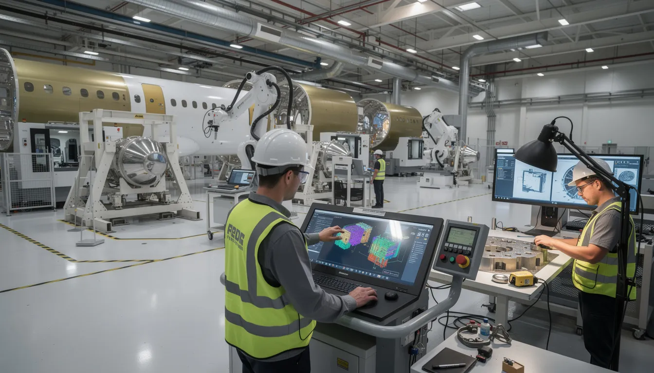
While Connect981 primarily serves aerospace manufacturing and MRO operations, understanding automotive quality management systems provides valuable context for how structured quality frameworks have developed across safety-critical industries. Many of the themes found in IATF 16949, including traceability, supplier oversight, and rigorous process control, parallel requirements in aerospace standards like AS9100.

Purpose and intent of the IATF 16949 automotive quality standard
The central purpose of IATF 16949 is to establish a common, globally harmonized set of quality management system requirements for organizations involved in automotive production and service parts. Before harmonization efforts began, automotive suppliers often faced competing quality requirements from different OEM customers, each with their own certification systems. The IATF standard was originally created to consolidate these expectations into a single framework that serves the entire automotive supply chain.
The core intent focuses on three interconnected objectives: defect prevention, reduction of variation and waste, and robust process control. Rather than treating quality as an inspection-based activity that catches problems after they occur, IATF 16949 emphasizes preventing defects before they reach the production process. This approach acknowledges that in automotive manufacturing, where a single component failure can cascade into recalls affecting millions of vehicles, prevention is far more cost-effective than correction.
IATF 16949 aligns with customer specific requirements from major OEMs including General Motors, Ford, Stellantis, Volkswagen Group, BMW, and Daimler Truck, among others. By providing a shared baseline for quality expectations, the standard reduces redundancy for suppliers who would otherwise need to manage multiple competing systems. The standard emphasizes customer satisfaction, risk-based thinking, and continual improvement as foundational principles, while leaving specific implementation approaches to individual organizations based on their context and resources.
From ISO/TS 16949 to IATF 16949: key changes and replacement history
IATF 16949:2016 formally replaced the previous technical specification, ISO/TS 16949:2009, with the new standard released in October 2016 and transition deadlines set through 2017 and 2018 by IATF and accreditation bodies. The designation change from “ISO/TS” to “IATF” reflects that the document is now owned and maintained directly by the International Automotive Task Force, though it continues to reference ISO 9001:2015 for its base requirements.
The transition was driven by several factors. First, ISO 9001:2015 introduced a significantly updated structure based on risk-based thinking, requiring alignment from sector-specific standards. Second, the automotive sector needed to address new technologies, including embedded software in vehicle systems, that were not adequately covered in the previous edition. Third, there was recognition that supplier quality and product safety requirements needed strengthening to reflect the increasing complexity of global automotive supply chains.
Several high-level areas were strengthened in IATF 16949:2016 compared to its predecessor. Product safety received explicit emphasis, with new requirements for organizations to demonstrate that safety-related products and manufacturing processes are controlled appropriately. Traceability requirements were enhanced to address the need for tracking critical components through complex supply networks. Warranty and field failure analysis expectations were formalized, requiring organizations to establish processes for analyzing field incidents, warranty returns, and customer complaints. The standard also introduced considerations for embedded software in automotive related products, acknowledging that modern vehicles depend increasingly on electronic control systems.
The first edition of the IATF standard represented an innovative document in how automotive quality requirements would be structured and governed globally. Each subsequent update has reflected changes to the underlying ISO 9001 framework while maintaining the automotive-specific emphasis on defect prevention and waste reduction that defines the IATF approach.
Relationship between IATF 16949 and ISO 9001
IATF 16949:2016 is a supplemental automotive QMS standard that must always be used together with ISO 9001:2015. Organizations pursuing certification are evaluated against a combined system, and certificates reflect compliance with both IATF 16949 and the underlying ISO 9001 requirements. There is no option to achieve IATF 16949 certification without meeting ISO 9001 in full.
The structural relationship follows the ISO 9001:2015 High Level Structure, also known as Annex SL, which organizes management system standards into ten clauses. This same structure appears across multiple ISO standards, enabling organizations to align quality management systems ISO 9001 with environmental management under ISO 14001 and occupational health and safety under ISO 45001. The shared architecture reduces complexity for organizations managing an integrated management system across multiple domains.
ISO 9001 baseline requirements establish foundational quality management principles including customer focus, leadership engagement, process approach, and evidence-based decision making. The seven quality management principles embedded in ISO 9001 provide the conceptual foundation that IATF 16949 builds upon.
IATF 16949 automotive additions overlay sector-specific requirements throughout the ten-clause structure. These additions include more detailed control of manufacturing processes, specific requirements for supplier quality management, formalized approaches to product safety, and expectations for automotive-specific tools and methodologies. The automotive requirements do not replace or relax ISO 9001 expectations; they extend them to address the particular risks and operational realities of automotive production.
This relationship enables straightforward integration with other stakeholders’ management system expectations while maintaining the automotive-specific rigor that OEMs require. Organizations already certified to ISO 9001 have a structural foundation in place, though the automotive-specific additions represent substantial additional requirements that reflect the complexity of the automotive sector.
Scope and automotive supply chain context
IATF 16949 applies to organizations involved in manufacturing and servicing automotive production parts, service parts, and accessory parts. This includes direct suppliers to OEMs, as well as organizations throughout the supply chain that provide materials, components, or processing services such as heat treating, plating, or painting. Certification bodies evaluate sites where customer-specified automotive products are manufactured, assembled, or supported.
The standard focuses specifically on serial production for on-road vehicles, including light vehicles, heavy trucks, and buses. Organizations involved in automotive production at any tier level may pursue certification, though the standard explicitly limits applicability to manufacturers. Contract organizations providing only services, distribution, or activities outside direct production are not eligible for IATF 16949 certification.
Certification expectations cascade through the automotive supply chain. Major OEMs typically require their Tier 1 suppliers to maintain IATF 16949 certification, and those suppliers in turn expect certification from their Tier 2 and Tier 3 sources. This creates a quality expectation that extends deep into global supplier networks, establishing IATF 16949 as the common language for quality management across geographic and organizational boundaries.
The global nature of automotive production makes harmonized quality requirements essential. Modern vehicles contain thousands of components sourced from suppliers across North America, Europe, China, Japan, and emerging markets. Just-in-time delivery requirements, distributed manufacturing, and complex logistics create conditions where a quality failure at any point can disrupt production across multiple facilities and geographies. IATF 16949 provides the consistent quality performance expectations necessary to manage these risks across the worldwide automotive supply chain.

Automotive-specific considerations within IATF 16949
This section provides a high-level overview of themes where IATF 16949 goes beyond generic ISO 9001 requirements. The focus is on concepts and their significance to the automotive sector, not on methods for achieving compliance.
IATF 16949 addresses several automotive-relevant topics that reflect the industry’s particular risks and operational demands:
Theme
Significance in Automotive Context
Product Safety
Vehicles carry passengers; failures create direct safety consequences requiring formalized controls
Component Traceability
Recalls may affect millions of units; traceability enables targeted response rather than broad recalls
Manufacturing Process Change Control
Process variations directly impact product quality in high-volume production
Externally Provided Products and Services
Multi-tier supply chains require consistent quality management across organizational boundaries
Field Performance Analysis
Large production volumes generate statistically significant performance data requiring systematic analysis
The standard acknowledges that automotive organizations commonly use specific tools and practices including Advanced Product Quality Planning, Production Part Approval Process, Failure Mode and Effects Analysis, Measurement Systems Analysis, and Statistical Process Control. While IATF 16949 does not prescribe these specific methodologies, they represent expected practices in most OEM-supplier relationships and support the standard’s emphasis on defect prevention and variation reduction.
Warranty data and field failure information receive particular attention in IATF 16949. The combination of high production volumes and extended vehicle lifecycles generates substantial performance data that organizations must analyze systematically. Customer feedback loops, including warranty returns and field incidents, provide essential input for continuous improvement and help identify problems that may not appear in manufacturing quality metrics.
While Connect981 focuses on aerospace and MRO operations, many of these themes parallel requirements in AS9100 and other aerospace standards. Serial-number traceability, supplier oversight, rigorous change control, and systematic nonconformance management appear across both industries, reflecting shared recognition that high quality products in safety-critical applications require structured quality systems.
High-level structure of IATF 16949:2016
IATF 16949 follows the ten-clause Annex SL structure established by ISO 9001:2015. This common architecture makes it straightforward for organizations to align multiple management systems and reduces the complexity of maintaining parallel quality, environmental, and safety frameworks.
The standard’s clause structure provides the organizational framework for automotive QMS requirements:
Clause 4: Context of the Organization establishes requirements for understanding the organization’s context, including the needs and expectations of customers, suppliers, and other stakeholders. Organizations must define the scope of their quality management system and understand the automotive supply chain context in which they operate.
Clause 5: Leadership addresses top management responsibility for the quality management system, including establishing quality policy, assigning roles and responsibilities, and demonstrating commitment to customer focus.
Clause 6: Planning covers quality objectives, actions to address risks and opportunities, and planning for changes. Risk management principles are embedded throughout, reflecting the risk-based thinking introduced in ISO 9001:2015.
Clause 7: Support addresses resources, competence, awareness, communication, and documented information. This includes requirements for infrastructure, manufacturing environment, and the knowledge necessary for effective quality management.
Clause 8: Operation contains the most extensive automotive-specific additions, covering operational planning and control, requirements for products and services, design and development, control of externally provided processes, production and service provision, release of products and services, and control of nonconforming outputs.
Clause 9: Performance Evaluation establishes requirements for monitoring, measurement, analysis, and evaluation, including internal audit and management review. Automotive-specific performance indicators supplement generic ISO 9001 expectations.
Clause 10: Improvement addresses nonconformity and corrective action, emphasizing defect prevention and continual improvement as ongoing organizational priorities.
Automotive-specific additions are embedded throughout these clauses rather than appearing in a separate section. This integration means that organizations must understand both the ISO 9001 base requirements and the automotive additions that apply to each clause.
IATF rules and governance context (including Rules 6th Edition)
The International Automotive Task Force functions as the consortium responsible for maintaining IATF 16949, associated rules, and oversight of the global certification scheme. The IATF membership includes major automotive manufacturers from North America, Europe, and Asia, along with national trade associations representing automotive suppliers in various regions.
The IATF Rules documents govern how certification bodies conduct audits, issue certificates, and maintain the impartiality required for credible third-party certification. These rules establish consistent practices across certification bodies worldwide, ensuring that an IATF 16949 certificate represents the same level of demonstrated compliance regardless of which accredited certification body performed the assessment or where in the world the certified site operates.
The IATF Rules 6th Edition takes effect on January 1, 2025, establishing revised expectations for how IATF 16949 audits and certification processes are managed. These updated rules reflect ongoing refinement of the certification scheme based on experience and feedback from manufacturers, suppliers, and certification bodies. The updates address audit practices, certification requirements, and oversight mechanisms that maintain the integrity of the IATF 16949 certification system.
These rules are directed primarily at certification bodies and auditors rather than at individual manufacturing sites. The successful implementation of IATF 16949 at a manufacturing organization depends on the organization’s quality management system, while the Rules govern how external parties evaluate and certify that system. A recertification audit follows the same fundamental requirements regardless of Rules edition, though specific procedural details may change.
Comparing automotive and aerospace quality frameworks
While IATF 16949 is specific to the automotive sector, aerospace organizations typically follow AS9100, which is also built on ISO 9001’s structure but with aerospace-specific clauses and regulatory considerations. Both standards share the common foundation of ISO 9001 quality management principles, creating conceptual parallels even though the industries face different regulatory environments and customer expectations.
Quality Theme
Automotive (IATF 16949)
Aerospace (AS9100)
Traceability
Component-level for recall management
Serial-number level for airworthiness
Configuration Management
Process change control emphasis
Design and build configuration control
Supplier Oversight
Cascading certification expectations
Flowdown of requirements to supply chain
Nonconformance Management
Systematic corrective action
Root cause analysis and preventive action
Customer Requirements
OEM-specific requirements
Regulatory (FAA, EASA) and customer requirements
Both frameworks emphasize strong traceability, configuration management, supplier quality oversight, and rigorous management of nonconformities and corrective actions. Advanced change control, production process validation, and field performance feedback loops appear as common themes across both industries, even though the specific standards and regulatory bodies differ.
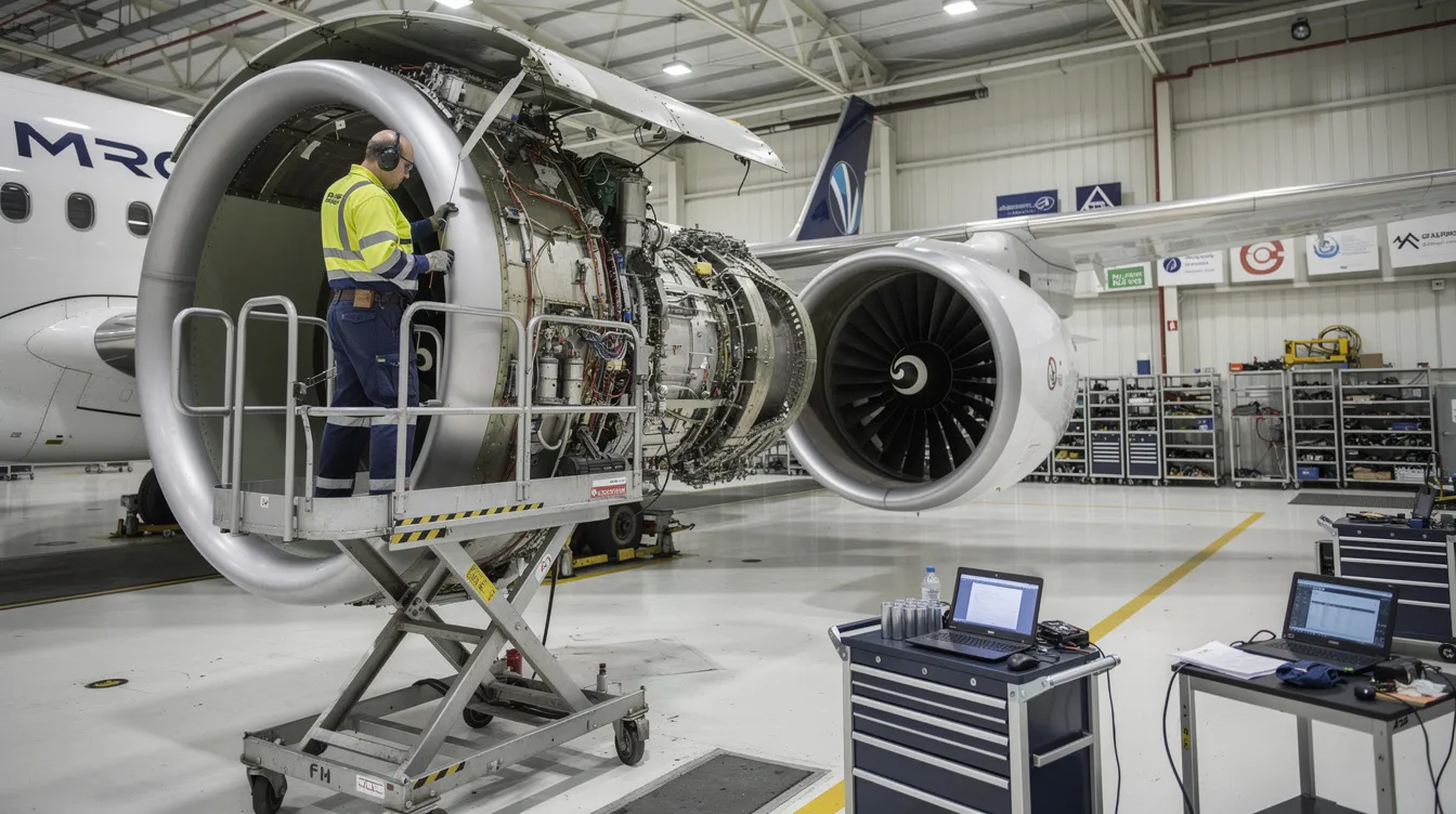
Connect981 is built around aerospace use cases, including AS9100 compliance, FAA and EASA regulatory requirements, and the particular demands of MRO operations. The same digital capabilities that support aerospace workflows, such as work instructions, defect logging, serial-number traceability, and supplier collaboration, reflect the maturity seen in highly structured frameworks like IATF 16949. Understanding how automotive quality management has evolved provides useful context for how these principles apply across safety-critical manufacturing sectors.
Summary: IATF 16949’s role in modern automotive quality management
IATF 16949:2016 remains the globally recognized automotive quality management standard that supplements ISO 9001:2015 and establishes common expectations across the automotive supply chain. The standard replaced ISO/TS 16949:2009 and brought automotive quality requirements into alignment with modern risk-based thinking while strengthening emphasis on product safety, traceability, and supplier quality management. IATF maintains strong cooperation with ISO through its liaison committee status, ensuring that the automotive framework evolves alongside broader international standard developments.
The standard’s primary contributions include harmonized quality management system requirements that reduce redundancy for global suppliers, an emphasis on defect prevention rather than detection-based quality approaches, and automotive-specific controls that reflect OEM expectations and applicable customer specific requirements. These elements work together to support customer loyalty by ensuring that vehicles meet quality and safety expectations across the production lifecycle.
While Connect981 operates primarily in aerospace and MRO environments, understanding IATF 16949 helps frame how advanced quality management and digital traceability have developed across safety-critical manufacturing sectors. The principles of efficiency, waste reduction, and systematic quality control that IATF 16949 embodies are not unique to automotive; they represent baseline concepts for any organization seeking to deliver high quality products in complex production environments.
Structured standards like IATF 16949 will continue to influence expectations for data integrity, supplier collaboration, and end-to-end quality assurance across industrial value chains. As supply chains become more interconnected and production systems more complex, the harmonized approach that IATF 16949 represents provides a model for how industries can establish common quality language and open new markets while managing the risks inherent in globally distributed manufacturing.