RSC Sphere: Buyer Proof and Enablement

The Buyer Proof and Enablement Sphere converts operational authority into decision confidence. It provides ROI models, proof assets, implementation playbooks, and comparison frameworks that buyers can use internally. The content removes ambiguity around outcomes, effort, and risk. This sphere turns credibility into momentum by making decisions easier to justify.

  • digital transformation roadmap

    A digital transformation roadmap is a structured plan for how an organization will move from its current operating model to a more digitally enabled one over time. It commonly lays out target capabilities, major initiatives, sequencing, dependencies, milestones, and decision points across business processes, systems, data, and people.

    In manufacturing and regulated operations, a digital transformation roadmap often covers areas such as MES, ERP, quality systems, data integration, electronic records, operator guidance, traceability, analytics, cybersecurity, and change management. The roadmap is not the transformation itself. It is the planning and prioritization framework that connects strategic goals to staged execution.

    What it usually includes

    • Current-state and target-state operating capabilities

    • Prioritized initiatives or workstreams

    • Dependencies between systems, processes, data, and teams

    • Phases, timelines, milestones, or release waves

    • Resource, governance, and adoption considerations

    • Measures used to track progress at a program level

    A roadmap may be expressed as a time-based plan, a capability maturity sequence, or both. Some organizations use it at the enterprise level, while others maintain separate roadmaps for plant operations, quality, supply chain, or OT and IT convergence.

    Operational meaning

    In day-to-day practice, a digital transformation roadmap helps explain why initiatives are being sequenced in a particular order. For example, a manufacturer might plan master data cleanup before MES deployment, or establish document control and electronic approvals before broader digital work instruction rollout. In this sense, the roadmap helps connect program intent, implementation timing, and cross-functional coordination.

    What it is not

    A digital transformation roadmap is not the same as a project plan, although project plans may sit underneath it. It is also not identical to a technology stack diagram, an IT budget, or a vendor implementation schedule. A roadmap is broader and usually includes operational, organizational, and governance elements in addition to software or infrastructure decisions.

    Common confusion

    Roadmap vs. project plan: a roadmap shows direction, phases, and dependencies at a higher level; a project plan manages detailed tasks, dates, and owners.

    Roadmap vs. digital strategy: strategy explains the desired business outcomes and operating principles; the roadmap translates that direction into a sequenced path.

    Roadmap vs. implementation backlog: a backlog is a working list of detailed items to be delivered; a roadmap groups and prioritizes larger initiatives over time.

  • Digital Work Instructions in Aerospace Manufacturing

    Digital Work Instructions in Aerospace Manufacturing

    Aerospace manufacturing operates under constraints that most industries never face. A single missed fastener on a fuselage section can ground an entire fleet. A procedural gap discovered ten years into production might require retrofitting hundreds of aircraft already in service. When programs run for 20 to 40 years and every serial number must maintain traceable documentation for its entire operational life, the systems that guide shop floor execution become foundational to both safety and business viability.

    Digital work instructions in aerospace are structured, interactive procedures delivered to operators through tablets, workstations, or dedicated HMIs. Unlike static documents or paper build books, these instructions connect directly to ERP, MES, and quality systems, creating a continuous record of what happened, when, by whom, and with what result. This page focuses specifically on aerospace and defense manufacturing and MRO work, covering airframes, engines, structures, and avionics rather than generic factory use cases. The stakes in this environment make the difference between paper based instructions and connected digital systems a matter of compliance, safety, and program survival.

    Digital work instructions improve build consistency, reduce errors, and are central to AS9100, NADCAP, FAA, and EASA compliance. One aerospace manufacturer reduced work instruction creation time from four days to one hour, while another eliminated assembly errors entirely, dropping from a 0.12% error rate to zero. These results reflect what becomes possible when instructions are no longer static documents but active guides that enforce standard work and capture data at the point of execution. Connect981 is built specifically for aerospace and MRO teams, unifying instructions, travelers, ERP and MES data, and supplier workflows in one digital layer. This article serves as the pillar overview, with deeper content available on digital travelers, version control, operator guidance systems, and MES integration.

    From Traditional Paper Work Instructions to Digital Manufacturing Instructions

    Aerospace factories have traditionally relied on layered paper-based systems to control work. Engineering drawing sets filled large binders at each station. Printed work instructions defined sequences, tool requirements, and acceptance criteria. Paper travelers moved physically with work orders, collecting signatures and dates as assemblies progressed through production. This approach emerged when aerospace was built in smaller volumes with longer cycle times per unit, and it worked adequately for that environment.

    The physical artifacts are familiar to anyone who has spent time on an aerospace shop floor. Paper travelers clipped to work orders, printed CAD screenshots with handwritten annotations, binder-based process documentation updated by hand, and tribal knowledge passed during shift handovers. On a narrow-body final assembly line, a work order arrives with a multi-part traveler showing part numbers, serial numbers, work center routing, and space for operator sign-offs. Next to the workstation sits a binder with printed instructions covering fastener installation, torque values, and required tools.

    Concrete examples illustrate how this plays out across different aerospace environments. Final assembly of aircraft sections involves hundreds of fastener holes, with operators manually checking off each location on paper checklists. Composite layup procedures from programs launched in the 2010s still rely on printed ply orientation tables and manual cure cycle logs. Engine MRO shops manage teardown, inspection, reconditioning, and reassembly through stacks of paper travelers that must be manually reconciled before an engine can be released.

    The terminology in this space can be confusing because different organizations use overlapping terms:

    • Work instructions are detailed, step-by-step guides for specific operations, tied to part numbers and configurations
    • Manufacturing instructions often serve as engineering-owned baselines from which site-specific work instructions are derived
    • Digital travelers are the digital equivalent of route cards, tracking work order progress and collecting data at each step
    • Routing sheets define the sequence of work centers and operations
    • Process documentation is the broad category encompassing all technical instructions, drawings, and standards

    Digital work instructions represent the structured, current source of truth that replaces these fragmented paper artifacts with a single controlled system.

    Long certification cycles compound the challenges. Programs spanning 20 or more years accumulate complexity as work instructions undergo dozens of revisions. Supplier changes, design improvements, service bulletins, and lessons learned from in-service issues all drive updates. In paper systems, controlling which version is current across multiple sites and suppliers becomes nearly impossible.

    Limitations of Paper and File-Based Instructions in Aerospace Operations

    Paper-based instructions create concrete operational risks that aerospace and defense manufacturers know well. Rework on major assemblies when a procedural step is discovered missing during final inspection. Concessions to OEMs when deviations from approved instructions are found. Missed first article inspection requirements because documentation cannot demonstrate that procedures were followed correctly.

    The core limitations include:

    • Version confusion: When a revised instruction is issued, it must be printed, distributed to every relevant site and supplier, and old versions must be physically removed from circulation. This rarely happens uniformly. A technician in one MRO facility might work from a 2015 revision while the official current version dates from 2023. There is no enforcement mechanism in paper systems, and auditors cannot definitively answer which version was used for a specific serial number.
    • Disconnected systems: ERP holds work orders and part master data. PLM stores engineering drawings and BOMs. QMS manages nonconformances. Paper travelers exist outside all of these systems. When a defect is discovered, quality must manually transcribe findings. When engineering issues a change, travelers in the field do not automatically update. Data silos proliferate, and no single system knows the complete history of a serial number.
    • Slow change management: Engineering changes are frequent in aerospace, especially during early production. In paper systems, the change process takes days or weeks: engineering issues a notice, manufacturing engineering revises instructions, quality reviews, documents are printed and distributed, operators are briefed, and old versions are collected. For urgent safety issues, this gap is dangerous.
    • Limited traceability: A traveler might show that a part visited a machining center and was signed off, but there is no link to which specific instruction revision the operator used. If a torque value was recorded manually, there is no verification that it was within tolerance. When an FAA auditor requires evidence that a specific process step was performed correctly, paper systems force weeks of manual record searching.

    Compliance gaps are particularly acute. AS9100 clause 8.5.1 requires controlled conditions for work execution, but paper systems cannot prove every operator used the current revision. FAA and EASA require traceable maintenance sign-offs, which paper logs struggle to provide definitively. NADCAP special processes require real-time parameter capture that manual worksheets filled out after the fact cannot deliver. ITAR controls on defense programs demand role-based access that printed documents cannot enforce.

    File-share and PDF-based approaches that appear digital create similar problems. Static pdf documents can be printed, emailed, or edited locally. There is no audit trail showing which version was actually used. Virtual versions stored on shared drives perpetuate the same version confusion as paper. These pseudo-digital systems provide none of the traceability or control that aerospace compliance requires.

    Operational impacts are measurable. Engineering changes reach the line late, causing rework. High-value titanium parts are scrapped due to procedural errors caught too late. Engine MRO turnaround time extends because technicians must call engineering for clarification on unclear instructions.

    Digital Work Instructions: Core Capabilities for Aerospace and MRO

    Modern digital work instructions are structured, interactive procedures delivered to manufacturing workers through connected devices. Each instruction guides the operator through a sequence of steps where actions can be validated, data can be captured automatically, and progression can be blocked when requirements are not met. The system connects directly to ERP, MES, and quality systems, ensuring that every execution is tied to a specific work order and serial number.

    A properly designed aerospace digital work instruction includes step-by-step flow with mandatory checks, embedded images and 3D views showing component locations, torque values with automatic validation against spec limits, and certified tool requirements verified before progression. Operators see guided workflows rather than static documents. The system actively prevents advancement to the next step until the current step is completed correctly.

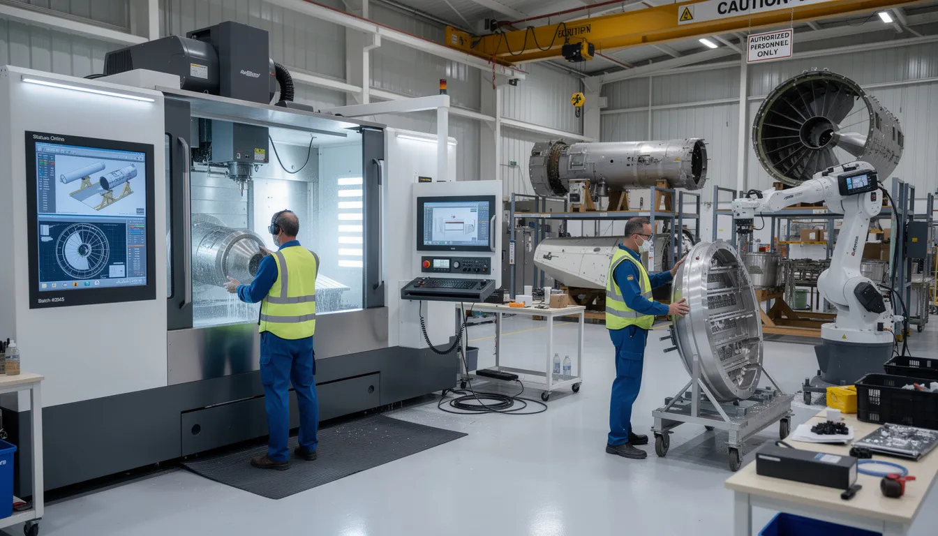
    An aerospace technician is using a tablet device to access digital work instructions while assembling an aircraft in a manufacturing facility. The digital transformation in aerospace and defense manufacturing enhances productivity and quality by providing real-time data and visual aids on the factory floor.

    Connect981 addresses these capabilities specifically for aerospace environments:

    • Embedded digital travelers showing routing and status, tied to each work order and serial number
    • Revision control and approval workflows ensuring only released instructions reach the shop floor
    • Part-level and serial-level traceability recording which operator performed which step, when, with what result
    • Integrated defect logging and nonconformance capture directly from the instruction screen
    • Support for final assembly lines, composite layup rooms, engine MRO cells, avionics repair benches, and supplier facilities
    • Connection to iot devices and torque tools for automatic data collection
    • Visual content including annotated drawings, 3D views, and photos from actual stations

    The glossary terms that recur throughout aerospace digital work instruction systems have specific meanings in practice. A digital traveler is the persistent record of a work order’s journey through manufacturing, holding routing information and collecting data at each operation. Revision control manages multiple versions of instructions, enforcing draft versus released states and documenting approvals. Manufacturing instructions are the procedural documents specifying how products should be manufactured. Process documentation is the broad category encompassing all technical guidance.

    How Digital Work Instructions Reduce Errors and Standardize Work

    Aerospace realities make error reduction essential. Escape defects can ground entire fleets. Concession costs run into millions. Flight safety incidents trigger regulatory scrutiny and program delays. Customer penalties for quality failures compound financial pressure on margins already stretched thin.

    Digital work instructions reduce errors through multiple mechanisms:

    • Guided step sequencing: Operators follow a defined sequence that prevents out-of-order execution. The system blocks progression until current steps are verified complete.
    • Required data entry: Certain fields cannot be left blank. Measurements, observations, and confirmations must be recorded before advancement.
    • Automatic validation: Tolerance checks compare recorded values against spec limits. Out-of-range entries are flagged immediately, before the operator moves on.
    • Tool verification: Connected torque tools, vision systems, and calibrated instruments auto-capture values and confirm correct tool usage.
    • Stop conditions: The system verifies prerequisites before allowing progression. If training records are missing or a previous step requires rework confirmation, execution is blocked.

    Results from aerospace implementations demonstrate the impact. Error rates dropped from 0.12% to zero. Scrap and rework reduced by 64%. Training time for new workers decreased by 50%. First time quality improved because defects were prevented rather than detected after the fact.

    Specific aerospace examples illustrate how this works in practice. Fuselage sections require hundreds of fasteners. Digital instructions can highlight each fastener location on a 3D model, require confirmation of each installation, and block completion until all positions are verified. Composite layup procedures demand precise fiber orientation. Digital systems track each ply, verify orientation, and log cure cycle parameters automatically from connected oven controllers. C-check and D-check MRO events involve hundreds of inspection steps. Digital instructions require evidence for each inspection, whether photos, measurements, or borescope images, ensuring nothing is marked complete without actual execution.

    Integration with inspection and measurement devices eliminates transcription errors. Real time data flows from torque wrenches, digital calipers, CMMs, and borescopes directly into the instruction system. Values are validated against tolerance bands instantly. This creates audit trails that prove not just what was recorded, but what actually happened.

    Standard work becomes enforceable across shifts and factories. Every operator at every site follows the same sequence, uses the same tools, and captures data in the same format. Multi-language and multi-unit variants operate under a single master revision. When instructions are updated, the update is instantly available everywhere. This standardization prevents the procedural drift that accumulates when frontline workers at different locations develop local variations.

    Supporting Compliance: AS9100, FAA/EASA, ITAR, and NADCAP

    Digital work instructions in aerospace are not primarily efficiency tools. They are compliance enablers that encode regulatory requirements and create audit ready records automatically. The documentation demands of aerospace and defense manufacturing make digital systems essential rather than optional.

    Core compliance themes addressed by digital work instructions:

    • AS9100: Clause 8.5.1 mandates controlled conditions for work execution. Digital systems prove control by maintaining revision history, tracking which instructions were used for which serial numbers, and linking execution to operator training and qualification records. Records retention becomes automatic rather than a manual archival project.
    • FAA/EASA: Maintenance documentation requirements demand traceable sign-offs tied to specific technicians and timestamps. Digital instructions capture exactly who performed each step, when, with what result. The complete maintenance history for an aircraft or engine becomes immediately accessible rather than scattered across filing cabinets.
    • NADCAP: Special processes like heat treat, non-destructive testing, and composite curing require parameter capture at the point of execution. Digital systems connected to oven controllers, NDT equipment, and cure monitoring systems log data in real time. The gap between process execution and parameter recording that exists in manual systems is eliminated.
    • ITAR: Defense programs require controlled access, data residency compliance, and role-based permissions that paper cannot provide. FedRAMP-ready cloud deployment or on-premises installation addresses these requirements. Access can be restricted to authorized personnel, with complete audit trails of who viewed or modified instructions.

    Connect981 maintains full audit trails covering who changed what instruction, when changes were approved, where instructions were executed, and which serial numbers were affected. Digital signatures tied to specific operators and timestamps replace handwritten initials that cannot be verified. Mandatory checklists ensure required steps are completed before progression. Automated escalation triggers when required approvals are skipped or when tolerance limits are exceeded.

    Maintaining compliance becomes an output of normal operations rather than a separate documentation exercise. Quality standards are encoded into the instruction workflow itself.

    Integration with ERP, MES, PLM, QMS, and Supplier Systems

    Digital work instructions function as the execution layer that sits on top of existing enterprise systems rather than replacing them. The goal is not to rip out ERP or MES but to create a connected layer that translates high-level work orders into guided shop floor execution and captures granular data for quality and compliance.

    Integration architecture for aerospace operations:

    • ERP sends work orders, part numbers, and due dates. As operators execute work, status updates flow back to ERP for accurate work-in-progress visibility.
    • PLM provides CAD drawings, BOMs, and engineering change data. Instructions reference the latest design, and when changes are issued, affected instructions are flagged for review.
    • MES or legacy systems track high-level routing while Connect981 manages detailed operator steps. The MES dispatches work to a work center; the digital instruction system guides what happens at that center.
    • QMS handles nonconformance workflows and CAPAs initiated directly from the instruction screen. When an operator discovers a defect, a nonconformance record is created automatically with all relevant context attached.

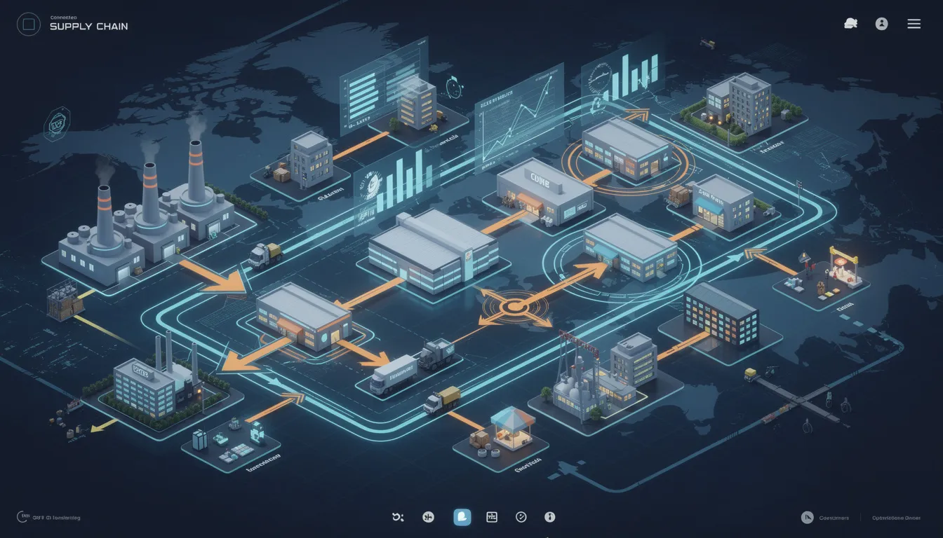
    Digital travelers pull and push data to these systems, creating a single consistent history per serial number. The digital thread connects design, manufacturing, and quality data into a traceable record that follows each part through its lifecycle.

    Multi-tier supplier integration extends visibility across the supply chain. Suppliers receive controlled access to work instructions, specifications, and change notifications through secure portals. As suppliers complete work, data returns to the OEM automatically. This visibility enables early defect detection and ensures supplier-manufactured parts meet the same quality standards as internal production.

    Real-time reporting becomes possible when manufacturing operations data flows from instruction execution. Production dashboards show WIP, bottlenecks, and quality trends without requiring manual data collection. Cycle time analysis, defect correlation, and operator performance tracking emerge from the same data captured during normal work.

    Digital Work Instructions Across Aerospace Use Cases

    Digital work instructions apply across the entire aerospace lifecycle, from prototype builds through rate production and into MRO and retrofit programs. The specific requirements vary, but the core need for controlled, traceable execution remains constant.

    Key aerospace scenarios:

    • New program industrialization: Early flight-test builds require rapid instruction updates as process issues are discovered. Digital systems enable same-day revisions with complete traceability of which serial numbers were built under which instruction version. A/B testing of different approaches becomes possible, with data showing which methods produce better outcomes.
    • Rate increases: Production ramps from 10 units per month to 40 units per month demand standardization across multiple assembly lines and sites. Digital instructions ensure every operator follows the same procedure regardless of location. New hires ramp faster because guided instructions reduce dependence on tribal knowledge and expert knowledge transfer.
    • Defense programs: Configuration control across multiple blocks (Block 1, Block 2, Block 3) requires instructions tied to specific configurations. Long service lives of 40 or more years demand documentation systems that can maintain records indefinitely. ITAR compliance requires controlled access that paper cannot enforce.
    • MRO and heavy checks: C-checks and D-checks involve hundreds of inspection and maintenance steps. Digital routing and instructions create complete maintenance histories tied to aircraft serial numbers. If a defect is discovered in service, the MRO work can be reviewed immediately to determine if the issue existed before maintenance or resulted from it.
    • Supplier manufacturing: Tier 1 and Tier 2 suppliers receive OEM-provided instructions to ensure consistency. Digital delivery with traceable completion data replaces paper packages sent via purchase order. The OEM gains visibility into supplier execution without requiring on-site audits for every operation.

    Connect981 adapts to mixed-model lines and complex options including customer-specific modifications, service bulletins, and retrofit kits. Instructions can be configured by variant, with the system automatically determining which version applies based on work order configuration.

    Designing Effective Aerospace Digital Work Instructions

    Manufacturing engineers and process owners responsible for authoring instructions need practical guidance for creating effective digital work instructions that operators can actually follow.

    Best practices for aerospace instruction design:

    • Start from validated templates tailored to aerospace tasks. Assembly, test, inspection, and rework operations each have common structures that can be standardized and then customized for specific applications.
    • Use clear, operator-focused language rather than pure engineering jargon. Reference spec IDs and drawing callouts accurately, but write for the person executing the work rather than the engineer who designed the process.
    • Include visual aids. Annotated drawings, 3D views, and photos from actual stations reduce ambiguity, especially for complex assemblies and harness routing. Videos demonstrating correct technique can accelerate training for new employees.
    • Build in checks and balances. Required data fields prevent progression without complete information. Automatic tolerance checks validate measurements against spec limits. Stop conditions block advancement when prerequisites are not met.
    • Consider training needs. Design instructions that can serve as on-the-job training content for new operators and cross-training programs. Include explanations of why steps matter, not just what to do.
    • Structure for multi-site deployment. Localizations for language, metric versus imperial units, and local tooling should be variants under one master process. When the master is updated, all variants update simultaneously.

    Connect981 offers drag-and-drop templates and zero-code workflow tools so process owners can design and deploy instructions without heavy IT involvement. This enables rapid iteration during early production when instructions change frequently and eliminates the bottleneck of waiting for IT resources to implement updates.

    Change Management, Revision Control, and Digital Travelers

    Unmanaged change is a primary source of defects in aerospace manufacturing. Engineering changes are frequent, especially during early production. When instructions change but operators use old versions, mixed lots and traceability gaps result. Paper systems cannot reliably control which version is current across distributed operations.

    Proper revision control in digital systems operates through defined states and workflows:

    • Draft vs. released states: Engineers work on draft revisions without affecting the shop floor. Only released revisions are visible to operators, preventing half-finished instructions from reaching production.
    • Approval workflows: Before release, revisions require approval from manufacturing engineering, quality, and sometimes customer representatives. Approval records are timestamped and archived.
    • Automatic archival and comparison: Every revision is stored with full metadata. Comparison tools show exactly what changed between versions.

    Digital travelers in Connect981 are always tied to the correct revision of work instructions for a given work order and serial number. The system enforces this binding automatically.

    Practical mechanisms for managing change:

    • Operators cannot access obsolete documents. The system presents only the current released revision for each work order.
    • Emergency deviations and temporary revisions can be implemented with controlled scope and automatic rollback when the deviation expires.
    • Complete records show which serial numbers were built under each revision. If a defect is traced to a procedural issue, affected units can be identified immediately for inspection or retrofit.
    • Version control prevents the scenario where an auditor asks which procedure was in effect for a specific build and no one can answer definitively.

    Data, Analytics, and Continuous Improvement from Instruction Execution

    Because every step of a digital work instruction is logged with timestamps, operator IDs, and measured values, the system generates granular data that powers continuous improvement and predictive quality. This data exists as a byproduct of normal work rather than requiring separate data collection efforts.

    Analytics capabilities from instruction execution data:

    • Step-level cycle times identify bottlenecks on assembly lines or MRO cells. If one step consistently takes longer than expected, investigation can reveal tooling issues, training gaps, or procedural inefficiencies.
    • Defect correlation connects quality issues to specific steps, tools, shifts, or operators. If a particular assembly step shows elevated defect rates, root cause analysis can focus there. If defects spike during a specific shift, workforce or supervision issues might be the cause.
    • Rework rate tracking by process, program, or supplier prioritizes improvement projects. Increasing rework rates signal growing problems before they become critical.
    • Operator performance monitoring compares execution across operators to identify training needs, skill certifications, and optimal task assignments. New hires can be tracked over time to measure ramp-up effectiveness and accelerate training programs.
    • Tool usage patterns reveal when equipment is drifting out of calibration or approaching end of life.

    Connect981 includes real-time dashboards and AI-assisted root cause analysis focused on aerospace operations data. Artificial intelligence can identify patterns that would take humans hours to spot, accelerating problem resolution.

    These insights directly support audit readiness. When an OEM auditor or FAA inspector asks for evidence that a specific procedure was followed correctly, reports can be generated in minutes rather than weeks. The execution history provides complete, timestamped documentation of every action.

    Analytics tie back to strategic initiatives like rate readiness and smart factory programs. The ability to continuously improve based on actual execution data rather than assumptions transforms digital work instructions from documentation tools into operational intelligence platforms.

    Implementing Digital Work Instructions in an Existing Aerospace Environment

    Implementing digital work instructions in established aerospace operations requires a practical approach that works alongside existing systems rather than forcing a complete infrastructure replacement.

    Phased adoption roadmap:

    • Assessment: Map current travelers, instructions, and compliance requirements across key programs and sites. Identify where paper processes create the most friction and where compliance gaps present the greatest risk.
    • Pilot: Choose a representative line or MRO cell to prove value and refine templates. A complex assembly operation or engine module works well because it exercises the full range of instruction capabilities without putting entire programs at risk.
    • Standardization: Define global templates for common process types and governance rules for authors. Establish who can create and approve instructions, what review processes are required, and how revisions flow to the shop floor.
    • Integration: Connect to ERP, PLM, MES, and QMS systems with focus on a few high-value data flows first. Work order dispatch and status updates typically provide immediate value. Broader integration can follow as the deployment matures.
    • Scale: Roll out to additional lines, sites, and suppliers using lessons learned and standardized training materials. The pilot team becomes champions who can support broader adoption.

    Involving manufacturing engineers, quality, IT, and frontline operators from the outset ensures the system is designed for actual use cases and builds buy-in for adoption. Operators who see the system reduce their daily frustrations become advocates rather than resistors.

    Connect981 is designed to run alongside existing ERP and MES with low IT overhead. The goal is deployment in months rather than the multi-year cycles associated with full system replacements. Digital transformation happens incrementally, proving value at each stage before expanding scope.

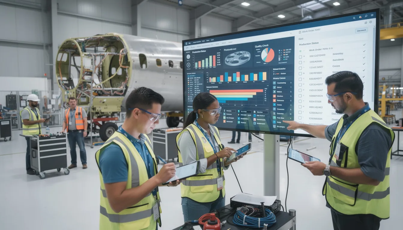
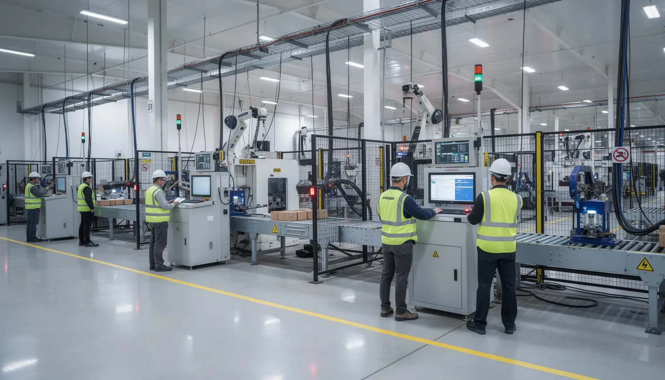
    A manufacturing team is collaborating around a digital display that showcases digital work instructions, enhancing their manufacturing operations. This setup emphasizes the importance of visual aids and real-time data in aerospace and defense manufacturing, promoting continuous improvement and reducing errors on the factory floor.

    How Connect981 Supports Digital Work Instructions for Aerospace Teams

    Connect981 acts as a unified operations layer specifically tuned for aerospace and MRO digital work instructions. The platform addresses the unique requirements of aerospace manufacturing, from serial number traceability to configuration control to the documentation structures required by AS9100 and FAA environments.

    Key capabilities that differentiate Connect981 for aerospace operations:

    • Aerospace-native data model: Serial number focus, configuration control, and documentation structures built for aerospace compliance rather than adapted from generic manufacturing systems.
    • Zero and low-code workflow builder: Manufacturing engineers can build and maintain instructions without heavy IT projects. Drag-and-drop templates and visual workflow builders eliminate paper and enable rapid deployment.
    • Cross-factory and cross-supplier visibility: One environment for OEM plants, MRO shops, and external suppliers with appropriate access controls.
    • Integrated quality and traceability: Defect capture, inspection checklists, and full audit trails tied to each instruction step create audit readiness as a byproduct of normal operations.
    • Fast deployment: Pilot to multi-line rollout in months rather than multi-year MES replacement cycles.
    • Mobile devices support: Operators access instructions on tablets and workstations appropriate for their work environment.
    • Connected tool integration: Torque tools, iot devices, and measurement equipment integrate directly for automatic data capture.

    The platform saves time by eliminating manual documentation, paper reconciliation, and the compliance scramble that precedes audits. Efficiency gains compound across operations as standardized processes replace scattered tribal knowledge.

    Next Steps and How to Get Started

    Conclusion digital work instructions: the shift from paper based work instructions to connected digital systems is foundational to consistent, compliant aerospace manufacturing. Error reduction, standardized work, and audit ready documentation emerge naturally when instructions guide operators through validated procedures and capture data at the point of execution. The technology exists today to eliminate paper and transform how aerospace and defense manufacturers control factory floor operations.

    For manufacturing engineers, operations leaders, and quality managers evaluating this transition, start by identifying one pilot area where digital work instructions would provide immediate value. Look for processes with high rework rates, compliance pressure, or reliance on tribal knowledge that does not scale.

    Related content for deeper exploration:

    • Digital travelers and routing management
    • Work instruction version control and approval workflows
    • Operator guidance systems and error proofing
    • MES integration and connected shopfloor architecture
    • Reducing human error through digital guidance

    Request a demo of the Connect981 platform to see how these capabilities apply to your specific programs. Demos can be tailored to commercial, defense, or MRO operations and your existing system landscape. The path from paper to connected digital work instructions is shorter than most organizations expect when the platform is designed specifically for aerospace realities.

  • Do I need high-frequency sensor data to predict process drift effectively?

    No. You do not always need high-frequency sensor data to predict process drift effectively.

    What you need is data at a frequency that matches how the process actually drifts. If drift happens over hours, shifts, lots, or tool life, minute-level or event-based data may be sufficient. If the process changes in seconds or sub-seconds, then higher-frequency data may be necessary. The right answer depends on process physics, measurement quality, and how early you need to detect change.

    When high-frequency data matters

    Higher-frequency sensor data is more useful when:

    • The process is fast and unstable enough that meaningful variation is missed at lower sampling rates.
    • Short transients, spikes, vibration, pressure fluctuation, or thermal cycling are leading indicators of later quality loss.
    • You are trying to distinguish normal control behavior from emerging equipment or control-loop issues.
    • The cost of late detection is high enough to justify more storage, integration, validation, and model maintenance.

    When it is not necessary

    Many drift problems can be predicted with lower-frequency or non-sensor data, especially in brownfield environments. Useful signals often include:

    • SPC trends and inspection results
    • Batch, lot, or work-order outcomes
    • Tool changes and tool life data
    • Maintenance events and downtime codes
    • Recipe, routing, or setpoint changes
    • Environmental readings at practical intervals
    • Operator observations and exception records

    For slower processes, these sources are often more actionable than raw high-rate telemetry because they are closer to the actual quality and execution context.

    What usually matters more than sample rate

    In practice, prediction quality often depends more on data readiness than on raw frequency. Common limiting factors are:

    • Bad timestamps or weak time synchronization across PLCs, historians, MES, and quality systems
    • Missing context such as product, route, revision, tooling, operator, or material lot
    • Sensor drift, calibration issues, and inconsistent measurement systems
    • Too little history covering both normal operation and true drift events
    • Frequent process changes that invalidate prior model behavior
    • Poor integration between OT signals and MES, ERP, QMS, or maintenance records

    If those issues are unresolved, collecting data faster can increase noise and cost without improving prediction.

    Tradeoffs to evaluate

    Higher-frequency collection is not free. It can increase:

    • Storage and network load
    • Historian and edge infrastructure complexity
    • Cybersecurity and access-control scope
    • Validation effort for regulated use cases
    • Model tuning burden and false positive rates
    • Change-control overhead when tags, equipment, or recipes evolve

    That does not mean you should avoid it. It means the business case should be based on a specific failure mode, not a general belief that more data is automatically better.

    A practical approach

    Start by identifying the drift mechanism you are trying to catch: thermal shift, wear, contamination, calibration loss, material variation, control instability, or something else. Then estimate how quickly that mechanism develops and what signals change first.

    In many plants, the sensible path is staged:

    1. Use existing historian, MES, quality, and maintenance data to establish whether drift is visible at current granularity.
    2. Measure detection performance against known events, scrap, rework, or out-of-control conditions.
    3. Add higher-frequency capture only to the equipment, tags, or periods where lower-frequency data clearly misses important behavior.
    4. Maintain traceability for model inputs, versions, and changes if predictions influence decisions or investigations.

    This staged approach is usually lower risk than trying to instrument everything at maximum rate, especially where legacy systems, validated workflows, and constrained downtime are real constraints.

    Brownfield reality

    In mixed-vendor environments, high-frequency data is often trapped in controllers, OEM tools, or historians that do not map cleanly to MES, ERP, PLM, or QMS context. That integration gap is often the real blocker. Full replacement is rarely the practical answer in regulated, long-lifecycle operations because qualification burden, downtime risk, and traceability impacts can outweigh the benefit. Coexistence with existing systems is usually more realistic, but performance depends on integration quality and disciplined change control.

    So the short answer is: no, not by default. Use the minimum frequency that captures the physics of drift with enough lead time to act, and invest at least as much effort in context, data quality, and system integration as in raw sampling rate.

  • Can MES support formal quality methods like 8D or 5-Why in aerospace programs?

    Short answer

    Yes, most modern MES platforms can support 8D, 5‑Why, and similar formal problem‑solving methods, but typically as configurable workflows and data structures rather than turnkey “8D modules.” In aerospace programs, the practical limit is rarely the MES feature set; it is the need to align with customer‑specific procedures, QMS processes, existing CAPA systems, and validated document controls. You should expect to design, configure, and validate how the method is implemented in the MES and how it interacts with your QMS, not to switch it on like a template and be done.

    What MES can realistically do for 8D and 5‑Why

    MES can provide structured data capture for problem descriptions, containment actions, root cause analysis steps, and corrective actions, mapping them to 8D stages or 5‑Why chains. It can link nonconformances, defects, and work orders to specific investigations, ensuring traceability from shop floor events back to each analysis step. It can also enforce required fields, checklists, approvals, and electronic signatures before an 8D phase is considered complete. In some deployments, MES is also used to store 5‑Why trees, attachments (photos, test reports), and references to external records hosted in QMS or PLM. These capabilities are almost always configuration‑driven and must be aligned with documented procedures if they are to stand up in an aerospace audit.

    Where MES usually stops and QMS/CAPA takes over

    In many aerospace environments, formal 8D and 5‑Why work is owned by the QMS or CAPA system, not by MES. MES typically initiates or feeds the investigation through nonconformance records, scrap/rework data, and process history, while QMS tools manage the official 8D report, customer communication, and CAPA lifecycle. Trying to move the entire formal method into MES can clash with established QMS workflows and customer‑approved templates. As a result, MES is often best used as the operational evidence source (who, what, where, when) and as the trigger for 8D/5‑Why, while the QMS remains the system of record for the formal problem‑solving file. When lines are blurred, you need clear governance about which system owns which records and approvals.

    Integration, traceability, and validation constraints

    To make MES truly useful for 8D and 5‑Why in aerospace, integration with QMS, ERP, and sometimes PLM is more important than individual MES features. You need reliable and traceable links between nonconformances, work orders, serial/lot records, test results, and the corresponding 8D or 5‑Why entries. If integrations are weak, out‑of‑sync, or poorly documented, you risk duplicated records, inconsistent root causes, and audit challenges when you try to reconstruct a full history. Any MES workflows that support formal quality methods must be under change control and validated in line with your quality system and customer expectations. That means configuration changes to forms, fields, routing, or e‑signatures can carry a non‑trivial validation and documentation burden.

    Tradeoffs: MES‑centric vs QMS‑centric problem solving

    Using MES as the primary tool for 8D and 5‑Why can improve access to real‑time production data and make root cause analysis more evidence‑based. However, it can also fragment your quality record set if your QMS remains the required system of record for CAPA and customer reporting. A QMS‑centric approach keeps formal investigations in one place but often requires engineers to manually pull information from MES or rely on reports and exports. In a brownfield aerospace environment, a hybrid model is common: MES captures detailed operational context and enforces containment on the shop floor, while the QMS hosts the formal 8D file and external communication. The right balance depends on your existing validation commitments, your customers’ expectations, and how much integration debt you can tackle without disrupting operations.

    Why “rip and replace with MES problem‑solving” often fails in aerospace

    Replacing existing QMS‑based 8D/5‑Why workflows with a new MES‑embedded solution is rarely straightforward in aerospace. Formal problem‑solving processes are usually embedded in customer requirements, contracts, and long‑standing procedures, all of which require controlled updates and sometimes customer approval. Moving the method into MES effectively creates a new validated workflow that must be documented, tested, and justified to auditors and customers. You also risk breaking established links to document control, training records, risk management, and certification evidence that live outside MES. Because of validation cost, change‑control overhead, and the risk of disrupting ongoing programs, incremental coexistence and integration are usually safer than full replacement.

    Practical implementation considerations for aerospace programs

    When configuring MES to support 8D or 5‑Why, start by mapping your current approved procedure and templates to specific MES fields, workflows, and approval steps. Decide explicitly which system is the system of record for the formal 8D report and which systems only provide supporting evidence. Make sure investigations can be traced from defect detection (e.g., operator reject in MES) through analysis, corrective action, and verification of effectiveness, even if the data spans multiple platforms. Pay special attention to how you handle revisions and re‑opens of 8D and 5‑Why records, since aerospace programs often revisit root causes years later. Finally, involve quality, operations, and IT early to ensure that any MES support for formal methods is compatible with your current QMS, validation strategy, and long‑lifecycle product obligations.

  • What is the highest paid job in supply chain?

    There is no single “highest paid” supply chain job across all companies. Pay at the top end is driven less by the job title label and more by scope, P&L impact, regulatory exposure, and scarcity of expertise.

    Roles that typically sit at the top of the pay range

    In industrial, regulated environments, the highest compensation is usually found in roles like:

    • Chief Supply Chain Officer (CSCO) or EVP/VP Supply Chain with global scope and direct influence on P&L, inventory, working capital, and service levels.
    • Head of Operations / COO with supply chain accountability, where manufacturing, logistics, and supplier management sit under one executive.
    • VP/Head of Procurement or Strategic Sourcing in materials-intensive businesses (aerospace, pharma, medical devices, semiconductors, energy) where supplier risk, long lead equipment, and regulatory exposure are high.
    • VP/Head of Planning & Logistics in organizations where supply chain reliability is mission critical (e.g., aftermarket support, defense programs, high-mix low-volume with contractual penalties).

    At the executive level, total compensation is often dominated by bonuses and long-term incentives tied to inventory turns, service levels, cost of goods, and program milestones. In some firms, the COO with strong supply chain scope will earn more than a CSCO in another firm; title alone does not guarantee the pay band.

    Highly paid non-C-suite supply chain roles

    Below the C-suite, some roles can reach very high compensation when tied to high-consequence risk or scarce skills:

    • Senior Director / Director of Supply Chain in a major site or business unit with full responsibility for planning, materials, logistics, and supplier performance.
    • Director of Supplier Quality & Development in aerospace, defense, or life sciences, where supplier issues directly affect certification, recalls, or contractual penalties.
    • Director of Integrated Business Planning (IBP/S&OP) when they orchestrate demand, supply, and financial planning across multiple plants and regions.
    • Director of Logistics & Network Design for complex global networks with trade compliance, cold chain, or hazardous materials constraints.
    • Technical specialist roles (e.g., senior supply chain architect, network optimization expert, advanced planning systems lead) embedded in operations or IT, where deep systems and data integration skills intersect with regulated operations.

    These roles often command high pay because they sit at the intersection of supply continuity, regulatory risk, and major capital or operating costs.

    Key factors that drive the top end of pay

    Compensation at the top end of supply chain roles depends heavily on context:

    • Industry and regulatory burden: Aerospace, defense, pharma, and medical devices often pay more than light manufacturing or distribution because supply failures have higher legal, safety, and contractual exposure.
    • Scope and scale: Global multi-plant networks, complex supplier ecosystems, and high-mix low-volume manufacturing typically pay more than a single local site.
    • P&L and balance sheet impact: Roles directly accountable for inventory, working capital, material cost, logistics spend, and on-time delivery trend higher than “advisory” or narrow functional roles.
    • Exposure to critical programs: Program-critical roles in long-lifecycle equipment (airframes, turbines, therapeutics, fabs) are often paid at a premium because delays or shortages cascade into major financial and contractual impact.
    • Brownfield systems competence: In many plants, leaders who can improve performance without full system replacement, and who understand MES/ERP/QMS/MRP coexistence, are more valuable than those proposing greenfield overhauls with high validation and downtime risk.
    • Talent scarcity: Deep knowledge of export controls, regulated cold chain, advanced planning engines, or multi-tier supplier risk often pushes pay higher.

    Why there is no universal “top job”

    Across regulated, long-lifecycle industries, the highest paid supply chain role could be a CSCO in one company, a COO with integrated supply chain in another, or a highly specialized procurement or logistics executive in a third. Structural differences matter:

    • Ownership: Private equity ownership may drive aggressive incentives tied to working capital and cost reduction. State-owned or family-owned firms may have different bands.
    • Geography: Pay levels vary significantly between regions and even between major hubs within a region.
    • Org design: Some companies centralize planning and procurement; others push responsibility to business units or plants. Pay follows where accountability actually sits, not just title labels.

    As a result, there is no single job title that is always the highest paid in supply chain. The most consistently high-compensation category is senior leadership with end-to-end supply chain accountability and direct impact on financial and regulatory risk.

    Implications if you are planning your career

    If you are deciding where to specialize, focusing solely on the theoretically highest paid job is usually less practical than building toward roles with broad accountability and scarce skills:

    • Seek experience where planning, procurement, logistics, and manufacturing operations intersect, not just one narrow function.
    • Develop fluency in MES/ERP/MRP and QMS integration, and understand change control, validation, and traceability requirements.
    • Take on roles with real accountability for service levels, inventory, and supplier performance, not just analysis or reporting.
    • In regulated environments, build credibility around risk management, audit readiness, and compliance-aligned process improvement.

    Over time, those capabilities are what typically open the door to the better-paid senior director, VP, and C-level supply chain roles.

  • What does work order mean?

    In industrial and regulated manufacturing environments, a work order is a formal, authorized instruction to perform defined work on a product, component, batch, or asset. It is both a planning object and a control record that ties the work to specific materials, documents, people, equipment, and timestamps.

    Typical purpose of a work order

    A work order is used to:

    • Authorize work to be done (production, rework, maintenance, calibration, or inspection).
    • Specify what must be done (operations, tasks, or steps).
    • Reference how to do it (routes, travelers, work instructions, drawings, specifications).
    • Identify which units are affected (serials, lots, batches, assets, locations).
    • Capture evidence that it was done (signatures, timestamps, data, measurements, nonconformances).

    Common types of work orders in regulated operations

    • Production work order (or shop order): to build a defined quantity of a part or assembly, typically created from MRP/ERP and executed in an MES or on paper travelers.
    • Rework or repair work order: to perform specific corrective work on nonconforming or returned product, often tied to a deviation or nonconformance record.
    • Maintenance work order: to perform preventive or corrective maintenance on equipment, tools, or facilities, commonly managed in a CMMS or EAM system.
    • Calibration work order: to perform calibration or verification on gauges and measurement systems, with results feeding back into metrology and quality records.

    Key information usually contained in a work order

    The exact fields vary by system (ERP, MES, CMMS) and by plant, but most regulated environments include:

    • Identifiers: work order number, revision, plant/area, asset or line.
    • Scope: part number or asset ID, quantity or specific units, type of work (build, inspect, rework, maintain).
    • Linked documents: bill of materials, routing, work instructions, drawings, specifications, permits.
    • Schedule & responsibility: required start/finish dates, assigned department or cell, responsible owner.
    • Materials & resources: required components, tools, fixtures, test equipment, special processes.
    • Execution records: operator or technician identifiers, timestamps, results, measurements, deviations.
    • Approvals: electronic or physical signatures for creation, release, completion, and sometimes QA review.

    How work orders relate to other systems

    In brownfield environments, the work order typically sits at the intersection of multiple systems:

    • ERP/MRP often creates production work orders for planning, costing, and inventory control.
    • MES or line control systems use the work order to drive execution, data capture, and traceability at the operation level.
    • QMS may reference work orders in nonconformance, CAPA, or deviation records, especially for rework and concessions.
    • CMMS/EAM manages maintenance and calibration work orders for assets and equipment.

    In many plants, these are only partly integrated, so the same work order ID might appear across systems, or separate IDs may need to be cross-referenced manually. How cleanly this works depends on integration quality, master data discipline, and change control.

    Constraints and variations

    • Naming differs: some sites use job order, shop order, process order, or batch record for similar concepts.
    • Granularity varies: a single work order may cover an entire build, a specific operation, or only certain serial numbers or lots.
    • Paper vs digital: many regulated plants still rely on paper travelers or mixed paper/digital records, which affects how the work order is created, updated, and archived.
    • Regulatory impact: in aerospace, medical, and similar environments, work orders are part of the permanent quality record and must be controlled, versioned, and retained under formal procedures.

    Because of these variations, when someone says “work order” in your facility, you usually need to clarify whether they mean a production order, maintenance order, rework order, or the combined traveler and record used on the floor.

  • How does MES reduce unplanned downtime?

    What MES can and cannot do about unplanned downtime

    MES reduces unplanned downtime primarily by improving visibility, coordination, and discipline around how equipment is run and maintained. It does not prevent failures by itself and will not eliminate all unplanned stops, especially in mixed, aging equipment fleets. The real benefit comes from detecting issues earlier, reacting faster, and learning systematically from each downtime event. In regulated environments, the effectiveness of MES is limited by validation scope, operator adoption, and how well it is integrated with automation, CMMS, and quality systems.

    An MES is most effective when downtime is caused by avoidable factors like scheduling conflicts, material shortages, changeover errors, or recurring process issues. It is less effective at stopping true random failures such as sudden component breakage with no prior indicators. Even then, it can still shorten the recovery time by providing clear instructions, standard work, and accurate status to maintenance and operations. Plants that treat MES as a silver bullet usually end up disappointed; plants that treat it as a data backbone and enforcement layer for existing reliability processes tend to see more realistic improvements.

    Real-time visibility into equipment status and constraints

    A core way MES reduces unplanned downtime is by giving operations and maintenance near real-time visibility of machine status, causes of stop, and performance trends. Instead of learning about issues when a queue has already built up or an order is at risk, supervisors can see that a line is trending unstable and intervene earlier. This relies on robust connections to PLCs or data historians and on consistent configuration of status codes and reason trees. If these integrations are weak or partially implemented, the MES view may be incomplete or misleading.

    In brownfield environments, some equipment will never be fully integrated, and operators will still enter status manually. This can introduce delays and classification errors, so the MES must be configured to separate auto-captured data from manual entries and make those differences visible. Over time, analyzing this status data helps identify chronic micro-stops, nuisance alarms, and bottleneck machines that drive unplanned downtime. Without a sustained effort to clean up status codes, train operators, and maintain mappings, MES dashboards can become cluttered noise rather than actionable insight.

    Better planning to avoid avoidable stops

    Unplanned downtime is often driven by planning failures masquerading as equipment issues: missing materials, unavailable tools, overlapping changeovers, or operators assigned to two critical tasks at once. MES can reduce this class of unplanned stops by enforcing realistic sequencing, availability checks, and material staging rules at dispatch time. When MES is integrated with ERP, WMS, and tooling systems, it can block or warn on orders that cannot reasonably run, turning what would have been a “surprise” stop into a visible constraint earlier in the process.

    In most brownfield plants, these integrations are partial, and many checks still rely on tribal knowledge and manual verification. MES helps only to the extent that master data (BOMs, routings, resource calendars) are accurate and maintained under change control. If planning data are outdated, MES may push infeasible schedules more efficiently, which can actually increase unplanned downtime. The tradeoff is that tighter MES enforcement can initially surface more late orders and conflicts; dealing with this requires management willingness to fix upstream planning and not just blame the system.

    Faster detection and escalation of emerging problems

    MES can shorten the time between the onset of a problem and effective response by automating alerts, workflows, and escalation paths. When a machine stops or performance degrades below a threshold, MES can trigger notifications to maintenance, quality, or engineering, including relevant context like last good part, active recipe, and environmental data. This shifts the pattern from operators informally “chasing” support to a more structured and traceable response process. However, if alert thresholds and routing are not tuned carefully, teams can quickly be overwhelmed by false or low-value notifications.

    In regulated environments, every change in alarm logic, workflow, or escalation rule may require impact assessment, configuration control, and in some cases re-validation. This can slow down optimization and result in conservative, static configurations that underperform. Plants need to deliberately prioritize which failure modes justify automated MES escalation and which remain manual. Done well, this reduces the mean time to respond and mean time to repair; done poorly, it just shifts the noise from radios and phone calls into on-screen popups and emails.

    Structured capture and analysis of downtime events

    An MES typically provides structured downtime reason codes, comment capture, and reporting, which supports more rigorous root cause analysis. By classifying each event with consistent codes and linking it to product, order, shift, and resource, the plant can move beyond anecdotes and guesswork. Over time, this reveals patterns such as specific SKUs or changeovers that disproportionately trigger stops, or particular machines with recurring, poorly understood failures. The value depends heavily on how disciplined operators and supervisors are in choosing accurate reasons and entering meaningful notes.

    If the reason tree is too granular, operators will guess or pick the first item; if it is too generic, analysis will remain vague and unhelpful. In many brownfield implementations, old habits persist and people treat MES downtime entry as a compliance chore rather than a tool to improve their work. Without management follow-through—reviewing reports, closing the loop with corrective actions, and updating reason structures through change control—the MES becomes a passive logging system rather than an engine for reducing unplanned downtime. The tradeoff is between data accuracy and operator burden; each plant must tune this carefully.

    Supporting maintenance and condition-based interventions

    MES is not a maintenance system, but it can complement CMMS or EAM by providing operating context, runtime counters, and usage-based triggers. For example, MES data can feed maintenance scheduling based on actual operating hours, cycles, or number of changeovers, rather than fixed calendar intervals. This can reduce both over-maintenance and unexpected failures, especially on high-criticality assets. It also helps coordinate maintenance windows with production plans, so that planned interventions do not accidentally cause additional unplanned disruption.

    In practice, these benefits only materialize if MES and CMMS are bidirectionally integrated and both data structures and processes are aligned. In many regulated plants, these integrations are either missing or limited to simple notifications, because deeper coupling increases validation scope and complexity. In such cases, MES may still help by providing better visibility to runtime and stop patterns, but maintenance teams must manually translate that into work orders. The tradeoff is between tight coupling with higher automation (and validation burden) and looser coupling with more manual but flexible workflows.

    Why MES alone will not eliminate unplanned downtime

    No MES can fully compensate for fundamental issues such as aging equipment near end-of-life, poor spare parts availability, inadequate maintenance practices, or chronic under-staffing. In aerospace-grade and similar regulated environments, aggressively replacing legacy controls or systems to enable more automation can actually increase risk by expanding qualification and validation scope, extending downtime for commissioning, and introducing integration failures. MES should be layered on top of existing validated equipment and processes, augmenting them rather than trying to replace them wholesale.

    Full replacement strategies often underestimate not just technical integration complexity, but also the need to maintain traceability, audit trails, and validated states while changing how downtime is captured and acted upon. Every new MES feature or interface that influences product quality or traceability has to be assessed, documented, and verified, which slows rapid iteration. As a result, improvements in unplanned downtime are usually incremental and uneven across lines, not a step-change. A realistic approach is to target the top few downtime drivers with MES-enabled interventions, measure impact, and then expand scope gradually, instead of expecting the system to solve all reliability problems by itself.

  • How fast can a small aerospace shop realistically deploy MES?

    A small aerospace shop can sometimes deploy a narrow MES pilot in about 8 to 16 weeks, but that usually means a controlled scope: one value stream, one product family, limited integrations, and a clear decision about what remains manual. A production-grade MES rollout across the shop more commonly takes several months, and a fully integrated, validated deployment can take 6 to 18 months depending on data quality, process maturity, customer requirements, and legacy system constraints.

    What can be done quickly

    The fastest realistic deployment is usually not a full MES replacement. It is a focused pilot around digital travelers, work instructions, labor capture, basic quality checks, and limited traceability for a defined routing or cell.

    This can move quickly if the shop already has stable routings, part masters, revision controls, operator roles, inspection steps, and a clear owner for process decisions. If the pilot avoids deep ERP, PLM, and QMS integration at first, the technical build may be manageable in weeks rather than months.

    That does not mean the system is fully institutionalized. Training, validation evidence, work instruction governance, exception handling, and supervisor adoption still determine whether the deployment is usable after go-live.

    What usually slows it down

    Small shops are not automatically simple shops. Aerospace work often has serialized parts, revision-sensitive work instructions, AS9100 expectations, AS9102 first article requirements, customer-specific flowdowns, export-controlled data, nonconformance workflows, and long-lived programs. These requirements affect MES design even when headcount is low.

    Common schedule drivers include:

    • Master data quality: routings, operations, BOMs, inspection plans, tooling, skills, and revision links must be reliable enough to execute from.
    • Integration scope: ERP, PLM, QMS, calibration, maintenance, and document control connections add time, especially in brownfield environments.
    • Validation and change control: regulated operations need evidence that the configured process works as intended and that changes are controlled.
    • Exception handling: rework, MRB, deviations, split lots, partial completions, scrap, and customer holds often expose gaps in a simple pilot design.
    • Operator adoption: if the MES adds clicks without removing ambiguity or paper burden, usage quality degrades quickly.

    Why full replacement is rarely the first move

    For most small aerospace shops, replacing ERP, legacy travelers, document control, quality workflows, and production reporting all at once is usually unrealistic. The qualification burden, validation cost, downtime risk, integration complexity, traceability obligations, and long equipment or program lifecycles make big-bang replacement a high-risk path.

    A more realistic approach is staged coexistence. The MES takes over defined execution controls first, while ERP remains the system of record for orders, inventory, purchasing, and finance. PLM or document control remains the authority for released engineering data. QMS remains the authority for formal quality records unless and until an approved integration or process change moves that responsibility.

    A practical planning range

    For planning purposes, a small aerospace shop should treat these ranges as starting assumptions, not commitments:

    • 4 to 8 weeks: discovery, process mapping, data assessment, pilot scope, and configuration design.
    • 8 to 16 weeks: narrow pilot for one area if data and decisions are ready and integrations are limited.
    • 3 to 6 months: first production rollout with controlled integrations, training, governance, and validation evidence.
    • 6 to 18 months: broader shop deployment with ERP, PLM, QMS, nonconformance, inspection, and traceability integration.

    These ranges can expand if the shop has unstable routings, inconsistent revision control, poor inventory accuracy, custom customer reporting, export-control constraints, or unresolved ownership between operations, quality, engineering, and IT.

    The practical answer

    If the goal is a visible MES pilot, a small aerospace shop may be able to move in one quarter. If the goal is a durable, audited, integrated operating system for production execution, plan in phases and expect the work to continue beyond the first go-live. Speed is possible only when scope is narrow, data is ready, interfaces are limited, and change control is treated as part of the deployment rather than an afterthought.

  • What MES data do I need before starting AI projects in aerospace?

    You do not need a perfect MES before starting AI projects in aerospace. You do need data that is usable, governed, and tied to a narrow business question. In practice, the required MES data depends on whether you are trying to predict delays, detect quality risk, reduce rework, improve labor planning, or identify process drift.

    A good rule is this: start with one decision you want to improve, then confirm you have enough historical MES and adjacent system data to reconstruct what happened, when it happened, to which part or assembly, under which revision, at which operation, using which resources, and with what outcome.

    Minimum MES data foundation

    For most aerospace AI use cases, the minimum useful data set includes:

    • Work order, traveler, or routing execution history by operation

    • Part number, serial number, lot, and where applicable full genealogy links

    • Timestamps for operation start, stop, queue, hold, completion, and rework events

    • Resource context such as workcenter, machine, tool, line, or cell

    • Operator or role information, if allowed by policy and handled appropriately

    • Disposition outcomes such as pass, fail, scrap, rework, deviation, or concession status

    • Nonconformance references and defect or symptom codes

    • Recipe, process plan, routing revision, and work instruction revision in effect at execution time

    • Material consumption and component issue records where product risk depends on material lineage

    • Equipment or test results if process capability or condition affects quality or throughput

    If you cannot connect execution records to outcomes, AI will usually produce weak correlations rather than operationally useful guidance.

    What matters more than data volume

    In regulated aerospace operations, data quality usually matters more than raw volume. A smaller, well-controlled history with reliable timestamps and revision context is often more useful than a large, messy export. Before starting, check for these basic conditions:

    • Consistent identifiers across MES, ERP, QMS, and where relevant PLM

    • Stable event timestamps and time zone handling

    • Clear status transitions rather than free-text updates

    • Reason codes that are actually used consistently on the floor

    • Versioned master data for routings, resources, and instructions

    • Enough history to cover normal variation, engineering changes, and atypical events

    If your plant has frequent manual overrides, backfilled transactions, shared generic logins, or uncontrolled free text, say so early. Those are common realities, but they directly limit model reliability and explainability.

    Use-case-specific data needs

    Different AI projects need different MES depth.

    • Delay and bottleneck prediction: queue times, operation durations, dispatch status, resource calendars, holds, shortage status, and rework loops.

    • Quality risk prediction: defect history, inspection/test results, parameter readings, operator steps, material lots, genealogy, and revision history.

    • Scrap and rework reduction: nonconformance codes, disposition paths, prior process conditions, tool or machine context, and process deviations.

    • Knowledge capture and guidance: standard work adherence, step completion records, exceptions, and links to controlled instructions.

    • Scheduling or labor recommendations: route variability, touch time versus elapsed time, skill constraints, and actual vs planned completion by operation.

    If the project touches product quality, airworthiness records, or release-adjacent decisions, expectations for traceability, validation, and change control go up quickly. That does not make AI impossible, but it changes the burden of proof.

    Data you probably need beyond MES

    MES alone is often not enough. In brownfield aerospace environments, useful AI usually depends on stitching MES to nearby systems:

    • ERP: order status, shortages, supplier delays, cost signals, and inventory state

    • QMS: NCR, CAPA, dispositions, audit evidence, and recurring defect patterns

    • PLM: revision effectivity, change history, and engineering context

    • Test and equipment systems: measured values, calibration state, equipment events, and environmental conditions

    • Document control systems: released work instructions and approval history

    This is where many AI programs stall. The issue is usually not model selection. It is unresolved identifier mapping, conflicting timestamps, poor lineage, and missing business rules across systems.

    What you do not need on day one

    You do not need a full digital thread, complete automation, or years of perfectly labeled data to begin. You can often start with one bounded use case if you have:

    • a stable process segment

    • a measurable outcome

    • several months of trustworthy event history

    • basic traceability to revision and outcome

    • a team willing to validate whether outputs are operationally credible

    For many plants, the first sensible step is not a plant-wide AI deployment. It is a data-readiness assessment and a narrow pilot on one product family, line, cell, or recurring quality issue.

    Common failure modes

    • Starting with a generic AI platform before defining the operational decision

    • Assuming MES transaction data reflects actual shop floor behavior without checking workarounds

    • Ignoring engineering change timing and revision effectivity

    • Treating free-text defect descriptions as a substitute for structured cause or disposition data

    • Underestimating rework loops, split lots, and serialized genealogy complexity

    • Trying to replace core MES, ERP, or QMS systems as part of the AI initiative

    That last point matters. Full replacement strategies often fail in regulated, long lifecycle environments because qualification burden, validation cost, downtime risk, integration complexity, and traceability requirements are high. In most aerospace plants, AI has to coexist with existing MES, ERP, PLM, and QMS systems rather than forcing a reset.

    A practical readiness threshold

    You are probably ready to start if you can answer these questions with evidence:

    • Can we reconstruct the execution history for a part, assembly, or work order?

    • Can we link execution events to quality and schedule outcomes?

    • Can we identify which revision, instruction, material lot, and resources were in effect?

    • Can we explain major data gaps, overrides, and manual steps?

    • Can we validate outputs without disrupting production or controlled processes?

    If the answer is no to most of these, the right next step is usually data remediation and integration cleanup, not model development.

    So the short answer is: you need enough MES and adjacent-system data to support traceable, revision-aware, outcome-linked analysis for one specific use case. Not more than that, but also not less.

  • Supplier Collaboration in Aerospace: Digital Systems, Portals, and Workflows

    Supplier Collaboration in Aerospace: Digital Systems, Portals, and Workflows

    Modern aerospace programs depend on thousands of suppliers spread across continents. An A320neo program sources structural components, avionics, engines, and special processes from Tier 1 integrators down to Tier 3 machine shops and heat treaters. A single Boeing 737 MAX involves precision castings from one region, composite layups from another, and NADCAP-certified surface treatments from a third. When any link in this aerospace supply chain breaks down, the consequences cascade through the entire value chain.

    The years between 2020 and 2024 exposed just how fragile manual, email-driven collaboration can be. COVID-19 factory shutdowns delayed deliveries by up to 50% in some cases. The 737 MAX recertification process extended supplier requalification timelines by 12 to 18 months. Persistent LEAP engine delivery delays, attributed to titanium forging bottlenecks, forced production rate adjustments across narrow-body programs. Industry-wide, on-time delivery shortfalls of 20 to 30% became common. These disruptions proved that spreadsheets, scattered email chains, and disconnected file shares cannot support the pace and precision aerospace demands.

    This article serves as a practical guide for aerospace OEMs, Tier 1 suppliers, and MRO organizations evaluating supplier collaboration systems. The focus is on purpose-built aerospace tools rather than generic procurement software or spend analysis platforms. Connect981 is designed specifically for aerospace and MRO workflows, sitting on top of existing ERP, MES, and QMS systems to connect suppliers, factories, and engineering data in one shared layer. The core capabilities covered here include supplier portals, digital RFQ workflows, supplier scorecards, change order management, and supplier documentation systems.

    What “Supplier Collaboration” Really Means in Aerospace Operations

    Supplier collaboration in aerospace extends far beyond purchase orders and invoice processing. It encompasses joint planning for lead times, quality standards, configuration management, and documentation exchange across a tiered network of suppliers. When an OEM and its suppliers are aligned, parts arrive on time, conform to specifications, and carry complete certification records. When alignment fails, programs stall.

    The typical aerospace value chain flows from OEMs through Tier 1 structural and systems integrators, who in turn rely on Tier 2 and Tier 3 specialists in machining, composites, chemical processing, and special processes. A Tier 3 heat treater using an outdated furnace qualification can cascade into airworthiness risks, delaying programs by months and costing millions. The 737 MAX supply chain disruptions post-2019 grounding demonstrated exactly how misalignment at any tier can ripple through the entire network.

    Key collaboration areas in aerospace include:

    • RFQs and sourcing for complex parts with multi-page specifications
    • Order promise and capacity visibility to match production ramps
    • Engineering change propagation across multiple supplier tiers
    • Quality and nonconformance resolution via supplier corrective action request workflows
    • Documentation and certifications tied to specific serial and lot numbers
    • MRO spares and repairs coordination for in-service fleet support

    A regulatory overlay of AS9100, NADCAP, FAA/EASA airworthiness directives, and ITAR export controls makes casual, spreadsheet-based collaboration both risky and difficult to audit. Supplier management processes must generate audit trails that withstand scrutiny from customers, regulators, and internal quality teams. A modern supplier management system ties these touchpoints into unified, automated workflows rather than scattered portals, emails, and file shares.

    Core Capabilities of Modern Aerospace Supplier Collaboration Systems

    An aerospace-ready supplier management platform differs fundamentally from generic vendor management software. The workflows, data models, and compliance requirements are specific to this industry. The following five pillars define what a mature aerospace supplier collaboration system should provide.

    • Supplier portals: Secure access for suppliers to view RFQs, purchase orders, engineering drawings, quality specs, and delivery forecasts in one place
    • Digital RFQ and sourcing workflows: Structured processes for complex aerospace parts that capture specifications, certifications, and evaluation criteria in auditable records
    • Supplier scorecards and performance reviews: Automated tracking of quality, delivery, cost, and responsiveness metrics over the life of the supplier relationship
    • Engineering and change order management: Controlled propagation of design changes, process updates, and configuration revisions across all impacted suppliers
    • Supplier documentation and traceability systems: Digital capture and linkage of certificates, test reports, FAI records, and process documentation to specific parts and serials

    Supporting capabilities include integration with ERP, MES, PLM, and QMS systems, role-based access control for ITAR and export control compliance, and audit-ready logging for AS9100 and FAA/EASA requirements. The sections that follow examine each pillar with aerospace-specific examples and practical implementation guidance.

    The image depicts a bustling industrial aerospace factory floor, where workers are actively assembling various aircraft components. The scene highlights the importance of supplier management processes and efficient supply chain management in the aerospace industry, showcasing a collaborative environment focused on product quality and operational efficiency.

    Supplier Portals for Aerospace: The Front Door to Collaboration

    Supplier portals are often the first visible component of a collaboration system. In aerospace, they must go well beyond basic PO views and invoice uploads. A portal that only shows order status fails to address the real coordination needs of complex programs.

    A modern aerospace supplier portal should allow secure access for suppliers to view RFQs, active purchase orders, quality requirements, the latest revisions of engineering drawings, process specifications, and delivery forecasts. Suppliers maintain their own certification records, upload required documentation, and respond to requests without waiting for emails or phone calls. The portal becomes the single source of truth for the commercial and technical relationship.

    Concrete aerospace use cases demonstrate the value:

    • A NADCAP-accredited heat-treat house uploads furnace run charts tied to specific lot numbers
    • A composite fabricator accesses updated layup sequences for LEAP engine fan blades
    • A precision machinist confirms capacity for a production ramp on A320neo brackets

    Self-service profile and certification management reduces manual follow-ups. Suppliers update their AS9100, NADCAP, and ITAR registration status, insurance certificates, and contact information directly. This approach cuts manual chases by an estimated 60% and eliminates audit surprises from expired certifications.

    Connect981 provides a shared portal that syncs with existing ERP systems like SAP or Oracle and quality management systems. This avoids duplicate data entry for supplier master records and ensures that supplier data remains consistent across systems.

    Designing a Supplier Portal That Aerospace Suppliers Actually Use

    Many suppliers ignore portals that are slow, confusing, or redundant with email. Legacy portal adoption rates often fall below 40% because the systems create more work rather than less. An effective supplier portal requires deliberate attention to usability and value.

    Usability requirements for high adoption include:

    • Simple navigation with clear task queues showing actions like “respond to RFQ” or “upload FAI report”
    • Mobile-ready interface for shop supervisors who work on the floor, not at desks
    • Minimal training needed for occasional users who may interact with the portal monthly
    • Transparent change logs showing what was updated and when

    Permission models must separate commercial data from technical data. ITAR and EAR export-controlled drawings require controls that limit access by user role and geography. A machining supplier in a non-U.S. location should not see controlled drawings unless proper export licenses are in place.

    Features that build trust include shared status trackers for RFQs and change requests, consistent notification rules that avoid email overload, and clear visibility into where a request sits in the approval process. When suppliers see value in using the portal, they engage.

    Connect981 emphasizes low-friction portal design. Small and mid-size machine shops, plating houses, and MRO partners can participate without requiring an IT department. High adoption correlates with 30% faster response times according to industry studies on digital supply chains.

    Digital RFQ and Sourcing Workflows for Complex Aerospace Parts

    RFQs for aerospace parts bear little resemblance to commodity purchasing. A request for landing gear actuators, composite spars, or engine mounts can span dozens of pages detailing materials like Ti-6Al-4V, special processes with NADCAP requirements for welding or coating, qualification cycles running 6 to 12 months for first article inspection, and volumes that may reach thousands of units per year across multiple aircraft programs.

    Managing these RFQs via email and spreadsheets generates predictable problems. Version confusion, lost attachments, and misinterpretation of requirements occur at rates approaching 25%. Digital RFQ workflows eliminate these failure modes.

    A structured digital RFQ workflow allows engineering and sourcing teams to publish controlled packages to pre-qualified supplier lists, solicit structured bids covering price breakdowns, lead times, capability matrices, and risk factors, and then generate automatic comparisons across all responses. A Tier 1 integrator issuing RFQs for A321XLR structural brackets to eight machine shops with different NADCAP coating requirements can streamline award decisions using weighted scoring models.

    Evaluation Criterion

    Weight

    Cost

    40%

    On-time delivery history

    30%

    Capacity and capability

    20%

    Geography and offset requirements

    10%

    The workflow supports iterative RFQs. When design changes occur, re-bids can be issued with updated requirements. Batch updates to due dates, captured clarifications, and Q&A threads remain inside the RFQ record for future audits and reference.

    Connect981 pulls BOM and configuration data from PLM and ERP, packages it into RFQs, and mirrors awarded work into execution workflows. This eliminates re-typing and reduces errors in translating requirements from sourcing into production.

    Standardizing RFQ Data and Evaluation Criteria

    Standard RFQ templates reduce ambiguity and supplier misinterpretation. When every RFQ follows a consistent format, suppliers know what to expect and procurement teams can compare responses directly.

    Mandatory data for aerospace RFQs should include:

    • Part numbers and revision levels
    • Material specifications and process requirements
    • Required certifications such as EN 9100 and specific NADCAP codes
    • Expected annual volumes and program duration
    • Target first article inspection dates
    • Packaging, shipping, and labeling standards

    Evaluation criteria should be visible and consistent across RFQs. Suppliers benefit from understanding how their bids will be scored, and sourcing leaders can justify award decisions to internal stakeholders and auditors using documented scoring models.

    Connect981 embeds these templates and scoring models as reusable, configurable workflows. Separate templates for rotorcraft, business jets, and defense programs ensure that program-specific requirements are captured without starting from scratch each time.

    Supplier Scorecards and Performance Management in Aerospace

    Aerospace supplier relationships often span 10 to 20 years. Supplier performance management must go beyond transactional metrics to encompass long-term capability evaluation, risk management, and collaborative improvement.

    A comprehensive supplier scorecard for aerospace typically tracks:

    Category

    Metrics

    Target

    Quality

    PPM defect rate, escape rate, FAI first-pass yield

    PPM <100, FAI yield >95%

    Delivery

    On-time delivery percentage, schedule adherence

    OTD >98%

    Cost

    Price trends, cost reduction contributions

    Per program targets

    Responsiveness

    Change acknowledgment time, corrective action closure

    <7 days acknowledgment

    Compliance

    Audit findings, certification status

    Zero open findings

    Consider tracking a precision machining supplier from 2021 through 2025 as build rates increased on a narrow-body program. Digital systems automatically pull data from ERP for delivery performance, QMS for nonconformances and SCARs, and MES for scrap and rework rates. This automation avoids the manual effort of spreadsheet scorecards that become stale within days of creation.

    The collaboration platform shares scorecards with suppliers regularly. Quarterly business reviews use shared dashboards to review trends and agree on improvement targets. This approach transforms scorecards from punitive reporting artifacts into joint improvement tools.

    Turning Scorecards into Joint Improvement Programs

    Scorecards should drive corrective and preventive actions rather than serve only as reporting artifacts. Supplier relationship management depends on converting performance data into concrete improvements.

    A structured cadence supports this transformation:

    • Quarterly business reviews with strategic suppliers using shared dashboards
    • Review of OTD, scrap/rework, and change responsiveness trends
    • Agreement on specific improvement targets for the next quarter
    • Documented action plans with owners and due dates

    Scorecard results link directly to improvement projects in the system. These may include process capability studies, additional inspection points, operator certification training, or co-investment in tooling and automation. When a scorecard shows recurring issues, the system generates workflows for root cause analysis and tracks closure of corrective actions.

    Tracking SCARs and 8D/CAPA outcomes against the supplier’s scorecard demonstrates trending improvements or highlights persistent problems. Connect981 logs supplier-specific actions, owners, due dates, and verification steps, creating audit trails that satisfy AS9100 requirements and customer audit expectations.

    Engineering Change and Change Order Management with Suppliers

    Design changes in aerospace programs are inevitable. Weight reduction initiatives, new alloy specifications, updated fastener requirements, and customer configuration requests generate engineering change notices that must propagate accurately across the supply chain. When changes are not controlled, costly deviations result.

    Types of changes relevant to aerospace supplier management include:

    • Engineering change notices from design and engineering teams
    • Change orders to contracts and purchase orders
    • Process changes at supplier facilities
    • Customer-driven configuration changes for specific aircraft tail numbers or operators

    Real programs have demonstrated the risks. The F-35 program experienced supplier-related deviations costing over $100 million when suppliers continued building to obsolete prints after weight reduction changes. Suppliers building to outdated revisions, making unapproved process substitutions, or missing serial-number trace updates following changes create airworthiness risks and delivery delays.

    A robust digital change management workflow notifies impacted suppliers, requires acknowledgment, tracks re-qualification requirements such as new FAIs or special process approvals, and ensures that ERP, MES, and portal data stay synchronized. The system prevents anyone from building or repairing to obsolete information.

    Connect981 serves as a coordination layer linking PLM and engineering changes to on-the-floor work instructions and supplier tasks. When an engineering change is released, the system propagates it to all affected parties with clear task assignments and acknowledgment requirements.

    An engineering team is intently reviewing technical documents displayed on their computer screens, focusing on supplier management processes and compliance monitoring within the aerospace supply chain. The collaborative atmosphere highlights their commitment to maintaining accurate supplier records and enhancing supplier relationships through effective vendor management software.

    Coordinating Multi-Tier Change Propagation

    A change to a single drawing can affect multiple tiers of suppliers. A casting foundry, machining shop, heat treater, and surface finisher may all be impacted by a material specification change. Digital systems must map BOM relationships and supplier assignments so that a single ECN triggers tasks and notifications across all affected parties.

    Workflows for supplier-initiated changes are equally important. Suppliers may propose alternative materials, new machining sequences, or different coating processes. These proposals require formal review and approval via documented processes that maintain accurate supplier records of what was approved and when.

    Full traceability requires recording which serial numbers or lots were built under which revision and change approvals. This data proves critical during FAA/EASA investigations or customer queries about specific aircraft. The digital thread must link changes to physical parts throughout the supply chain.

    Connect981’s audit logs and version control on work instructions and supplier documentation reduce disputes between engineering and suppliers about approval status. When questions arise, the system provides up to date data on exactly what was approved, who approved it, and when.

    Supplier Documentation, Traceability, and Compliance Systems

    In aerospace, documentation carries equal importance to the physical part. Incomplete certifications can ground aircraft or force scrapping of otherwise conforming material. Supplier documentation systems must capture, validate, and link documents to specific parts, serials, and lots.

    Typical supplier documents in aerospace include:

    • Certificates of conformity (CoC)
    • Material test reports (MTRs)
    • Special process certifications
    • First article inspection reports per AS9102
    • Process control records
    • Shipping documentation tied to serial and lot numbers

    Problems with paper and email-based documentation are well documented. Lost certificates, mismatched lot numbers, inconsistent naming conventions, and last-minute “doc hunts” before delivery or audits plague organizations using manual methods. Industry data suggests 10 to 15% loss or mismatch rates with paper-based approaches, causing 2 to 5 day shipment delays.

    A supplier documentation system addresses these issues by requiring suppliers to upload documents directly in the portal, tied to specific POs, parts, and serials. Validation rules and mandatory fields reduce errors at the point of upload. The system rejects submissions with missing information rather than discovering problems at inspection.

    Connect981 is designed around aerospace-grade traceability, linking supplier documents to shopfloor execution, inspection results, and MRO histories. This creates complete digital records that support both production and long-term maintenance requirements.

    Building End-to-End Digital Traceability Across Suppliers and MRO

    The same supplier documentation that supports initial production also supports maintenance and overhaul decisions years or decades later. Serial number tracking must flow continuously from raw material heats through supplier operations, special processes, assembly, installation, and future MRO events.

    AS9100 and customer audits require quick retrieval of all supplier records for a given serial, lot, or event. Auditors expect response times measured in minutes, not days. Organizations still relying on paper archives or scattered electronic files struggle to meet these expectations.

    Digital traceability has prevented major issues in real programs. When a supplier process deviation is discovered, organizations with strong traceability systems can quickly isolate affected serials and limit inspections to specific parts. Organizations without traceability face potential full-fleet inspections and extended groundings.

    Connect981’s shared data model allows both OEM/MRO operations and selected suppliers to see the same digital thread with appropriate access controls. This shared visibility eliminates the data collection overhead of requesting information from suppliers each time a question arises about part history.

    An aircraft is being inspected for maintenance inside a spacious hangar, with technicians carefully examining various components. This scene reflects the importance of compliance management and supplier performance in the aerospace supply chain, ensuring that the aircraft meets regulatory requirements and safety standards.

    Integrating Supplier Collaboration Systems with ERP, MES, PLM, and QMS

    Aerospace organizations already operate SAP, Oracle, legacy MES, and PLM tools like Teamcenter, Windchill, or 3DEXPERIENCE. A supplier collaboration system must integrate with these existing systems rather than attempt to replace them. Rip-and-replace approaches fail in aerospace because regulatory compliance depends on data continuity across production records.

    Key integration points include:

    System

    Integration Purpose

    ERP

    Supplier master data, purchase orders, accounts payable

    PLM

    BOMs, revisions, engineering changes

    QMS

    Quality events, nonconformances, CAPA tracking

    MES

    Work orders, shopfloor execution status

    A unified collaboration layer reduces duplicate data entry and discrepancies. Mismatched supplier codes across systems create compliance risks and operational confusion. When the approved supplier list syncs automatically between systems, procurement teams can trust that sourcing decisions align with quality approvals.

    Specific aerospace integration scenarios include synchronizing approved supplier lists by special process code, feeding supplier scorecard metrics back into sourcing approval workflows, and aligning engineering changes between PLM and supplier portal data. When these connections work, supplier information flows without manual effort.

    Connect981 operates as a lightweight, zero and low-code layer that bridges existing systems. The platform enables cross-factory and cross-supplier workflows without requiring a full MES or ERP replacement. Integration via APIs and configurable connectors allows IT teams to establish connections incrementally.

    Implementing Supplier Collaboration in Aerospace: Practical Steps

    Many aerospace suppliers still rely on fax, email, and paper for daily coordination. Rollout of digital collaboration systems must be staged and realistic. Attempting to onboard hundreds of suppliers simultaneously typically fails.

    A phased approach reduces risk and builds momentum:

    1. Pilot scope: Select a single airframe or engine program and a small group of strategic suppliers for initial deployment
    2. Process mapping: Document existing RFQ, change, and documentation workflows before configuring the platform
    3. Standard workflows: Define templates and approval workflows for the pilot scope
    4. Platform configuration: Set up the collaboration system with pilot-specific configurations
    5. Supplier onboarding: Train pilot suppliers with clear messaging on benefits and provide ongoing support
    6. Baseline measurement: Establish metrics for RFQ cycle time, supplier OTD, and documentation accuracy before and after

    Supplier engagement determines success. Training sessions should emphasize benefits that suppliers value: fewer email chains, faster approvals, clearer requirements, and reduced time spent answering the same questions repeatedly. New suppliers joining the program see a clear onboarding path rather than a confusing mix of emails and phone calls.

    Connect981’s low-code workflows and aerospace templates reduce IT dependence. Process owners in supply chain, quality, and MRO can iterate on workflows without waiting for development resources. This operational efficiency accelerates adoption and allows continuous improvement based on real usage patterns.

    Measuring the Impact of Supplier Collaboration Systems

    Digital collaboration investments should connect to tangible business outcomes. Generic claims about digital transformation provide little value. Concrete KPIs demonstrate whether the investment delivers results.

    Metrics to track include:

    Metric

    Baseline Comparison

    RFQ cycle time

    Days or weeks before vs. after implementation

    Supplier OTD percentage

    Trend over 6-12 months

    Supplier-related nonconformances

    Count and severity trends

    Documentation-related shipment holds

    Frequency and duration

    FAI right-first-time rate

    Before and after comparison

    Engineering change implementation time

    Days to full supplier acknowledgment

    Audit finding closures

    Time to resolve supplier control findings

    Before-and-after comparisons on a specific program build internal business cases. When a narrow-body production line demonstrates 15% improvement in supplier OTD and 25% reduction in RFQ cycle time, expansion to other programs follows naturally.

    Connect981 provides real-time dashboards and AI-assisted analytics to surface bottlenecks and recurring supplier issues proactively. Data driven decision making replaces reactive fire-fighting when leadership has visibility into compliance monitoring and supplier quality trends.

    How Connect981 Supports Aerospace Supplier Collaboration

    Connect981 unifies supplier portals, RFQs, scorecards, change workflows, and documentation in one aerospace-oriented management platform. Unlike generic procurement software or SAP Ariba implementations focused on indirect spend, Connect981 is built around the realities of aerospace production and MRO operations.

    Key differentiators include:

    • Built specifically for aerospace and MRO compliance requirements
    • Fast deployment via zero and low-code configurable workflows
    • Deep focus on traceability, digital work instructions, and audit readiness
    • Integration layer that connects ERP, MES, PLM, and QMS without replacement
    • Automation capabilities that reduce manual effort across internal teams and suppliers

    Example workflows demonstrate practical application:

    1. Supplier FAI submission and approval: Supplier uploads first article inspection report in the portal, tied to specific part numbers and serials. Quality team reviews and approves or requests corrections. Full audit trail captured automatically.
    2. Digital RFQ for complex machined assembly: Engineering packages BOM and specifications from PLM, sourcing distributes to qualified suppliers, structured responses enable comparison, and awarded work flows into execution workflows.
    3. Supplier-initiated process change request: Supplier proposes alternative machining sequence through formal channel. Engineering reviews, approves with conditions, and system tracks implementation across affected orders.
    4. MRO shop requesting supplier support: Maintenance organization identifies recurring field failure linked to supplier process. System links field data to supplier records and initiates joint analysis workflow.

    Aerospace manufacturers facing supply chain disruptions, compliance issues, or operational inefficiencies from disconnected systems can evaluate how Connect981 addresses their specific challenges. The platform supports compliance tracking, ongoing monitoring of supplier performance, and procurement operations that meet regulatory requirements.

    Request a demo to see supplier collaboration workflows applied to your programs and supplier network. The Connect981 team can demonstrate how the platform integrates with your existing systems and supports your specific aerospace and MRO requirements.