RSC Sphere: Data Integration, Security and Trust

The Data Integration, Security and Trust Sphere establishes the governance layer that makes everything else credible. It focuses on system interoperability, data mapping, version control, audit trails, and security alignment for regulated environments. The content makes clear how execution data can move safely across ERP, MES, QMS, PLM, and supplier systems without compromising control. This sphere proves that interoperability and security can coexist in aerospace ecosystems.

  • What are the most common ISO 27001 findings in manufacturing?

    In manufacturing, ISO 27001 findings usually cluster around a few patterns: incomplete scoping, weak basic controls on the shop floor, and poor evidence that controls actually operate as designed. The specific findings vary by plant, auditor, and integration maturity, but the themes below come up repeatedly.

    1. Incomplete or fuzzy scope for OT, MES, and test equipment

    Many manufacturing organizations define an ISO 27001 scope focused on corporate IT while leaving operations technology (OT) and production data only partially covered.

    • Common findings:
      • Production lines, test stands, PLC networks, and lab systems not clearly included or excluded in the Statement of Applicability.
      • Ambiguity about whether MES, historians, and QMS are in-scope when they run in plants but are hosted centrally.
      • No clear mapping of information security requirements to product, process, and quality data in OT systems.
    • Why it happens: Brownfield environments with legacy equipment, mixed vendors, and long asset lifecycles make scoping politically and technically difficult.

    2. Incomplete asset and information inventory

    Accurate inventories are a core ISO 27001 expectation, but plants often have large blind spots.

    • Typical gaps:
      • No consolidated inventory of OT assets (PLCs, HMIs, industrial PCs, data loggers, machine controllers).
      • Test benches, programming laptops, and engineering workstations missing from the asset list.
      • Information assets such as NC programs, routings, recipes, test data, and calibration records not classified or even listed.
      • Shadow systems (access databases, local spreadsheets, scripts) used for production decisions with no registration.
    • Manufacturing nuance: Many assets are embedded in machines that cannot easily be scanned or taken offline for discovery, and OEM support contracts sometimes constrain configuration visibility.

    3. Weak access control on shop floor and engineering systems

    Access control findings are very common, especially where IT identity practices did not extend into OT.

    • Common findings:
      • Shared generic accounts on HMIs, industrial PCs, test stations, and maintenance laptops.
      • No individual authentication for changes to machine parameters, PLC logic, or NC programs.
      • Inconsistent revocation of access for contractors, temp workers, and transferred employees.
      • Uncontrolled local admin rights on engineering workstations and programming tools.
      • Remote access to vendors without strong authentication, time-bound access, or robust logging.
    • Typical root causes: Legacy devices that do not support modern authentication, cultural resistance on the shop floor, and incomplete integration between corporate identity systems and plant assets.

    4. Insufficient change control for OT, MES, and automation

    ISO 27001 expects controlled changes to information systems. In many plants, IT change management is formal, but OT and automation changes are handled informally.

    • Frequent findings:
      • No formal process for changes to PLC code, robot programs, test sequences, or recipes.
      • Inadequate versioning and rollback capability for automation and MES configuration.
      • Security impact not assessed when process changes are implemented (for example, adding networked sensors, remote diagnostic access, or new data exports).
      • Poor linkage between change records, validation/qualification records, and security risk assessments.
    • Brownfield challenge: Upgrading or revalidating production systems can be expensive and downtime-constrained, so plants often defer security-motivated changes until auditors highlight the risk.

    5. Inadequate backup, recovery, and configuration management

    Backups exist for central IT systems, but production environments often have partial or inconsistent coverage.

    • Common issues:
      • No tested backups of PLC programs, recipes, or machine parameter sets.
      • Backups stored only locally on the same network segment or in ad hoc engineer-managed archives.
      • Lack of documented, tested recovery procedures for MES, SCADA, or key plant databases.
      • Recovery objectives (RPO/RTO) not defined or not realistic relative to production impact.
    • Impact on findings: Auditors often flag the gap between documented policies (for example, enterprise backup standards) and the actual state of OT and plant-level systems.

    6. Weak logging, monitoring, and incident handling in OT environments

    ISO 27001 requires detection and management of security events. OT environments frequently lag behind IT in this area.

    • Typical findings:
      • Limited or no central logging from PLCs, industrial PCs, and OT network devices.
      • No clear incident response process that covers production systems and cross-functional roles (operations, maintenance, IT, quality, EHS).
      • OT events not integrated with SIEM or monitored only through OEM tools that plants rarely review.
      • No correlation between cyber incidents and quality/nonconformance investigations.
    • Dependency: Achieving robust monitoring in OT often depends on vendor support, network segmentation quality, and the tolerance for adding monitoring tools without requalification.

    7. Removable media and data transfer controls

    Removable media are still widely used in manufacturing for NC programs, firmware, and recipes, and are a common source of findings.

    • Common findings:
      • No consistent controls for USB sticks used to move programs into CNC machines, printers, or testers.
      • Personal or unvetted media used to load software or diagnostics tools onto industrial PCs.
      • Lack of scanning procedures or quarantine steps before media is connected to OT assets.
      • No logging or traceability of how critical programs and data are moved between systems.
    • Brownfield reality: For older machines without network connectivity, removable media may be the only practical option, so organizations must design controls that work despite this constraint rather than assuming full elimination.

    8. Supplier, integrator, and OEM security oversight

    Manufacturing relies heavily on OEMs, system integrators, and outsourced services for systems that affect information security.

    • Typical auditor observations:
      • Supplier security requirements not aligned with ISO 27001 controls, especially for MES, OT integrators, and equipment OEMs that provide remote access.
      • No formal review of third-party access to production networks (for example, VPN tunnels, remote monitoring boxes).
      • Unclear ownership of patching and hardening responsibilities for vendor-supplied systems.
      • Limited due diligence for cloud services used to process production, maintenance, or quality data.
    • Constraints: Changing OEM practices or renegotiating contracts can be slow and may trigger requalification of validated systems.

    9. Policy, training, and awareness not adapted to plant realities

    Policies often exist on paper but are written for office staff, not for operators, technicians, and engineers.

    • Common findings:
      • General information security policies that do not mention OT, MES, or production-specific scenarios.
      • Training that covers phishing but not practical issues like handling USB drives for CNC programs or vendor remote access.
      • Operators and maintenance staff unaware of their specific responsibilities under ISO 27001 controls.
      • No evidence that training effectiveness is evaluated in production settings.
    • Tradeoff: Tailored training takes time away from production and often competes with safety and quality training, so it must be prioritized deliberately.

    10. Risk assessment and treatment not reflecting real plant risks

    ISO 27001 is risk-driven. Many findings arise because the risk assessment does not match operational reality.

    • Typical gaps:
      • Risk assessments performed centrally without plant input, missing realistic threat scenarios (for example, impact of OT ransomware on batch traceability or calibration data).
      • Underestimation of dependencies on single critical systems such as legacy MES, historians, or license servers for engineering tools.
      • No linkage between information security risks and existing risk frameworks used for safety, process, or quality.
      • Treatment plans not aligned with validation constraints, downtime restrictions, or OEM limitations, making them hard to implement.

    11. Documentation and evidence gaps

    ISO 27001 places strong emphasis on documented information and evidence that controls operate. In manufacturing, this often exposes inconsistencies between what is written and what happens during production.

    • Recurring findings:
      • Procedures updated for ISO 27001 on paper but not rolled out or followed in plants.
      • Missing or incomplete records for periodic reviews, access recertifications, and log reviews.
      • Security considerations not integrated into existing document control, change control, and validation processes.
      • Legacy systems operating outside formal documentation, for example, old test stands kept in service.
    • Dependency: Closing these gaps often depends on aligning ISO 27001 documentation with existing QMS, MES, and engineering document control, rather than creating stand-alone security documents.

    How brownfield constraints shape typical findings

    Most manufacturing plants operate brownfield environments with mixed generations of equipment, various MES and SCADA platforms, and heavy validation burdens. This shapes findings in several ways:

    • Some controls (for example, strong authentication, centralized logging) are difficult to retrofit into old equipment without major redesign or requalification.
    • Downtime windows are short, so remediation plans must be phased, and auditors may cite findings about slow implementation, not just initial gaps.
    • Full replacement of legacy systems purely for security reasons is rarely realistic; auditors look instead for documented risk acceptance, compensating controls, and clear roadmaps.

    Overall, the most common ISO 27001 findings in manufacturing are less about the absence of policies and more about inconsistent extension of those policies into OT, MES, and production data, constrained by long equipment lifecycles and integration debt.

  • Configuration versioning

    Configuration versioning is the practice of assigning identifiable versions to a system, application, device, process, or equipment configuration as it changes over time. It commonly refers to keeping a controlled history of settings, parameters, logic, mappings, templates, and other non-code configuration items so current and prior states can be identified and compared.

    In industrial and regulated environments, configuration versioning is used to understand what configuration was active at a given time, who changed it, when it changed, and what changed between versions. This can apply to MES rules, ERP integration mappings, PLC or SCADA parameters, electronic forms, work instruction settings, quality workflows, user-role configurations, and similar controlled setup data.

    Configuration versioning does not mean any change is automatically approved or released. It is about maintaining version identity and history. Approval workflows, change control, and document control may be related, but they are separate controls.

    What it typically includes

    • Version numbers, revision IDs, or other unique identifiers for a configuration state

    • Records of additions, removals, or edits to configuration items

    • Date, time, and user attribution for changes

    • Comparison between versions

    • Rollback or restoration to a prior known configuration, where supported

    • Linkage to deployment, release, or change records in broader governance processes

    Common confusion

    Configuration versioning is often confused with document version control and source code version control. Document version control applies to files such as SOPs, specifications, or controlled forms. Source code version control applies to software code. Configuration versioning focuses on operational settings and structured system behavior that may exist outside code files or formal documents.

    It is also distinct from a full audit trail. An audit trail may record every event or field-level change. Configuration versioning usually emphasizes named, recoverable configuration states and their revision history.

    Manufacturing context

    In manufacturing systems, configuration versioning commonly appears where system behavior must remain stable and explainable across production runs, quality events, or integration updates. Examples include versioned routing parameters in MES, revised inspection plan settings, changes to label templates, or updates to ERP-to-MES field mappings. The goal is to preserve a reliable record of which configuration was in effect for a given operation or period.

  • low-code platform

    A low-code platform is a software platform used to build applications, workflows, forms, dashboards, and integrations mainly through visual configuration rather than traditional hand coding. It commonly provides drag-and-drop design tools, reusable components, workflow logic, data models, and connectors to other systems.

    In manufacturing and regulated operations, a low-code platform is often used to create internal business applications such as deviation workflows, digital forms, approvals, maintenance requests, issue tracking, supplier collaboration steps, or simple MES-adjacent and quality processes. It can sit above existing systems like ERP, MES, QMS, or document control tools, or connect to them through APIs and integration services.

    What it includes and what it does not

    A low-code platform usually includes:

    • Visual application and workflow design
    • Prebuilt UI components and templates
    • Rules, logic, and approval routing
    • Data capture forms and basic reporting
    • Connectors or APIs for system integration
    • Security, roles, and deployment controls defined by the platform

    It does not automatically replace core transactional systems such as ERP, MES, PLM, or QMS. It is also not the same as custom software development, even though many low-code platforms allow some scripting or code extensions when needed.

    Operational meaning

    Operationally, a low-code platform is often the layer used to digitize manual or spreadsheet-based processes without building a full custom application from scratch. For example, a manufacturer might use one to create an operator escalation form, an NCR intake workflow, a training acknowledgment app, or a process exception review flow that exchanges data with ERP or MES.

    Where controls matter, organizations typically evaluate how the platform handles access, versioning, change management, audit trails, integrations, and data ownership. Those capabilities vary by product and configuration.

    Common confusion

    Low-code platform is commonly confused with no-code platform. No-code tools are generally aimed at users with little or no programming and rely more fully on configuration only. Low-code platforms usually still support technical users and may allow code for advanced logic, integrations, or user interface behavior.

    It is also commonly confused with an application platform or BPM/workflow tool. A low-code platform may include workflow and application functions, but the term refers more broadly to the development approach and tooling model, not only process automation.

  • industrial automation and control systems

    Industrial automation and control systems (IACS) are the combined hardware, software, networks, and related infrastructure used to monitor, control, and automate industrial processes and equipment. They are central to operational technology (OT) environments in manufacturing, energy, utilities, and other industrial sectors.

    IACS typically include sensors, actuators, controllers, human-machine interfaces, engineering workstations, and the communication networks that connect them. They may operate as stand-alone systems or be integrated with higher-level systems such as MES, SCADA, ERP, and quality management systems.

    Typical components of IACS

    While specific architectures vary, industrial automation and control systems commonly include:

    • Field devices such as sensors, transmitters, drives, and actuators that measure process conditions and execute control actions.
    • Controllers such as PLCs, DCS controllers, and RTUs that execute control logic and sequencing.
    • Supervisory systems such as SCADA, HMI, and historian servers that visualize, log, and coordinate process data and alarms.
    • Engineering and maintenance workstations used to configure control logic, update firmware, and manage system configuration.
    • Industrial networks and communication protocols that connect devices, controllers, and supervisory systems.
    • Supporting infrastructure including time synchronization, authentication services, and sometimes interfaces to IT systems.

    Use in manufacturing and regulated environments

    In manufacturing plants and other regulated operations, IACS are used to control production lines, utilities, and supporting processes. They influence product quality, equipment performance, data integrity, and worker safety. Example uses include:

    • Automated control of mixing, filling, packaging, and assembly operations.
    • Monitoring of critical parameters such as temperature, pressure, and flow.
    • Interlocks, safety functions, and shutdown logic at the control level.
    • Data collection for batch records, traceability, and audit trails when integrated with MES or quality systems.

    Because IACS directly affect physical processes, changes to configuration, software, or topology are often subject to formal change control, validation, and documented testing, especially in regulated industries.

    Relationship to cybersecurity and IEC 62443

    Industrial automation and control systems are a primary focus of industrial cybersecurity standards such as IEC 62443. In that context, IACS are treated as cyber-physical systems that require:

    • Identification and segmentation of control system assets and zones.
    • Defined roles and responsibilities for asset owners, integrators, and product suppliers.
    • Controls for secure development, configuration, operation, and maintenance over the system lifecycle.

    Cybersecurity for IACS considers not only confidentiality and integrity of data, but also availability and correct, timely control of the physical process.

    Scope and boundaries

    The term industrial automation and control systems commonly includes:

    • Process control systems (PCS) and distributed control systems (DCS).
    • Programmable logic controllers (PLCs) and their associated networks.
    • Supervisory control and data acquisition (SCADA) systems.
    • Building automation or utility control systems when they are part of industrial operations.

    It typically excludes general office IT systems (email, office productivity tools), business-only applications (CRM, HR), and consumer automation devices, even when they share similar technologies.

    Common confusion

    • IACS vs IT systems: IACS are focused on controlling physical processes in real time; IT systems are focused on information processing, storage, and business workflows. In many plants, the two are interconnected but governed differently.
    • IACS vs SCADA/PLC: SCADA or PLCs are specific system types or components. IACS is a broader term that covers the full set of industrial control equipment, software, and networks.
    • IACS vs OT: OT (operational technology) is a broad category of technologies that monitor or control physical devices and processes. IACS are a major subset of OT, focused specifically on automation and control.
  • OPC UA Industrial Interoperability

    OPC UA Industrial Interoperability

    Answering the Core Question: What Is OPC UA and Why Does Interoperability Matter?

    OPC UA, or OPC Unified Architecture, is an interoperability standard developed by the OPC Foundation and first released around 2008. Formalized as IEC 62541, it provides a vendor-neutral, platform independent framework for exchanging industrial data between controllers, equipment, software applications, and enterprise systems. Unlike earlier approaches that tied data exchange to specific operating systems or hardware, OPC UA was designed from the start to work across diverse systems, from embedded controllers running on ARM processors to cloud platforms handling enterprise analytics.

    OPC UA is not just a protocol. It combines communication services with information modeling, defining both how data moves between systems and what that data means. This distinction matters. Many protocols can transfer bytes between two endpoints, but OPC UA goes further by providing a structured way to describe the context, relationships, and semantics of the data value being exchanged. A temperature reading, for example, carries not just a number but metadata about its source, units, quality, and timestamp.

    Industrial interoperability refers to the ability of heterogeneous systems, including PLCs, DCS, scada systems, MES, ERP, analytics platforms, and cloud platforms, to understand and use each other’s data without requiring custom one-off interfaces. In modern industrial contexts such as Industry 4.0 and the industrial internet of things, this capability has become essential. OPC UA’s main conceptual contribution is a common language for data across operational technology and it systems. For aerospace and MRO operations, where reliable traceability, quality, and regulatory compliance are non-negotiable, interoperability is not a convenience but a prerequisite.

    The image depicts a modern industrial factory floor bustling with various automated machines and advanced control systems, showcasing the integration of OPC UA technology for reliable data exchange and industrial automation. The scene highlights the use of diverse systems and sensors, reflecting the principles of Industry 4.0 and the importance of standardized data in process control.

    From OPC Classic to OPC UA: Evolution Toward Interoperability

    The original OPC standard, sometimes called OPC Classic, emerged in the mid-1990s. At that time, “OPC” stood for “OLE for Process Control,” reflecting its roots in Microsoft’s OLE and COM technologies. OPC Classic was designed primarily to connect Windows-based HMIs and scada systems to process control equipment. For its era, it solved a real problem: before OPC, every integration between a PLC and a visualization system required custom drivers.

    Limitations of OPC Classic:

    Constraint

    Impact

    Windows dependency

    Could not run on Linux, embedded devices, or non-Windows platforms

    COM/DCOM complexity

    Firewall configuration and network security were difficult

    Fragmented specifications

    Separate standards for data access (opc da), historical access, and alarms

    Weak security model

    Not aligned with modern expectations for encryption and authentication

    By 2003, industry groups and the OPC Foundation recognized that a new approach was needed. The goals were clear: cross-platform support for ARM, x86, Windows, Linux, and embedded systems; secure communications with encryption and user authentication; and richer context for industrial data. The result was OPC UA, which unified earlier OPC specifications into one extensible architecture and introduced a modern, service-oriented design.

    OPC UA marked a shift from signal-level connectivity to information-level interoperability. Rather than simply moving data points between two systems, OPC UA enables those systems to understand the structure and meaning of what they exchange. Today, OPC UA support is embedded in industrial devices and software products across discrete manufacturing, process industries, energy, and building automation, making it a de facto reference for reliable data exchange.

    Core Concepts of OPC UA: Services, Models, and Neutrality

    Understanding OPC UA requires grasping a few foundational ideas that distinguish it from simpler protocols.

    Service-Oriented Architecture

    OPC UA defines a set of standardized services that any compliant implementation must support. These services include reading and writing data, subscribing to changes, browsing structures, calling methods, and publishing events. The specification describes what each service does, not how a particular vendor must implement it internally. This approach allows opc ua clients and opc ua server implementations from multiple vendors to communicate without requiring custom adapters.

    Information Modeling and Address Space

    Everything in OPC UA is represented as nodes within a structured address space. Nodes can be objects, variables, methods, or data types, and they are connected by typed relationships. This object-oriented approach allows both simple tags (like a single sensor value) and complex assemblies (like an entire machine with subsystems) to be modeled consistently. The information models describe not just the data source but the context and semantics of the data.

    Separation of Model and Transport

    OPC UA separates the logical information model from the transport layer. The same model can be carried over different encodings and transports, including binary TCP/IP, HTTPS, WebSockets, and even the user datagram protocol in certain contexts. This means the underlying system used for communication can change without altering the meaning of the opc ua data being exchanged.

    Vendor Neutrality

    The OPC Foundation governs OPC UA as an independent body. The opc ua specifications are publicly documented, and any vendor, integrator, or end user can implement servers and clients without proprietary lock-in. This neutrality is central to OPC UA’s value proposition. It does not favor specific products or platforms.

    Coexistence with Legacy Systems

    OPC UA is designed to coexist with legacy fieldbuses, PLC protocols, and higher-level business systems. It does not replace these other systems but provides a shared layer that can expose their data in a consistent, standardized form. For organizations with decades of installed equipment, this coexistence is practical and necessary.

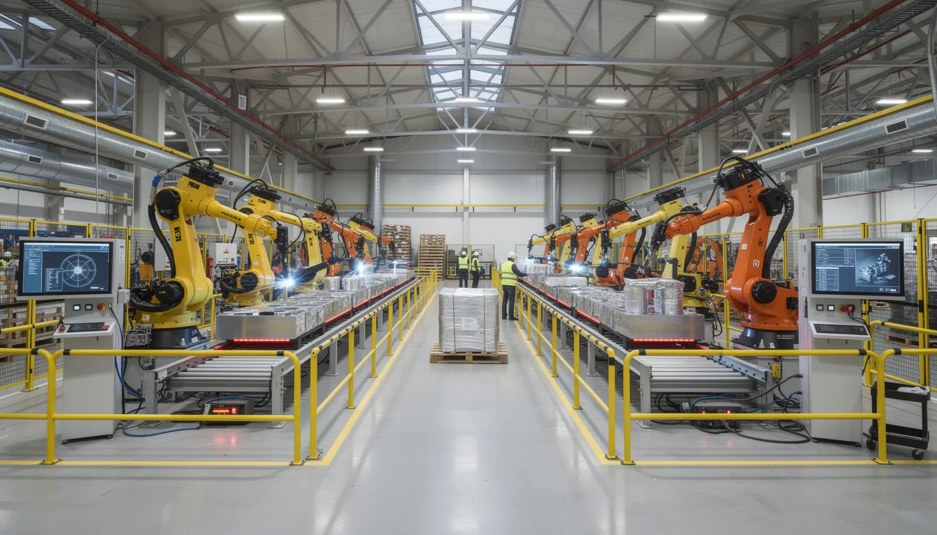
    The image depicts a manufacturing environment featuring advanced industrial automation equipment, including robotic arms and control panels. This setup highlights the integration of OPC UA technology for reliable data exchange and process automation in modern industrial systems.

    Why Industrial Interoperability Is a Strategic Issue

    Between 2010 and 2020, industrial operations became increasingly data-driven. The proliferation of sensors, the rise of MES and analytics platforms, and the push toward digital transformation created new demands for connectivity. At the same time, the heterogeneity of industrial systems became more pronounced.

    A typical plant today might include:

    • PLCs from multiple vendors with different native protocols
    • Specialized test stands and inspection equipment
    • Legacy historians from previous automation projects
    • Different MES deployments across sites or acquired companies
    • Multiple ERPs following mergers or global expansion

    Without standards, each connection becomes a custom interface. This increases project risk, maintenance cost, and the chance of misinterpretation of standardized data.

    Interoperability operates at three conceptual levels:

    Level

    Description

    OPC UA’s Role

    Physical connectivity

    Networks, cables, protocols

    Supports standard TCP/IP and web transports

    Syntactic interoperability

    Data formats and data types

    Defines structured data formats and encodings

    Semantic interoperability

    Shared meaning and context

    Provides information models with defined semantics

    OPC UA addresses primarily the syntactic and semantic levels. It defines standard structures so that data about temperature, torque, or serial numbers conveys the same meaning across industrial systems. For operations leaders, this translates into consistent quality records, reliable OEE metrics, unified traceability, and coherent root-cause analysis across production lines and sites.

    The Role of Open Standards in Industrial Data Exchange

    Open standards like OPC UA serve as long-term infrastructure for industrial data. Their value lies not in any single product but in the common ground they establish for an entire ecosystem.

    What “open” means in practice:

    • Publicly documented specifications (IEC 62541) available for review
    • Governance through a neutral foundation rather than a single vendor
    • Community involvement in developing and extending the standard
    • No licensing barriers to implementation

    Open standards reduce dependence on proprietary gateways and custom integrations. When every participant has a reference for how to structure and interpret industrial data, the engineering effort for each new connection decreases. The opc standard becomes shared infrastructure rather than a competitive differentiator.

    In complex environments, OPC UA commonly coexists with other standards. Industrial Ethernet variants, message queues, and fieldbuses all have their place. Interoperability often comes from combining these technologies rather than replacing one with another. OPC UA’s role is to provide a consistent, higher-level abstraction for data acquisition and exchange.

    Companion specifications, developed by industry working groups, extend the base OPC UA specification with domain-specific information models. These models capture shared concepts for machine tools, robots, energy systems, injection moulding machines, and other assets. When two systems implement the same companion specification, they can understand each other’s structures and semantics without custom mapping.

    For aerospace, energy, and process industry assets that operate for decades, a stable, vendor-neutral data description outlives individual software versions and hardware generations. This long lifecycle support is a strategic advantage of open standards.

    OPC UA Information Modeling and Companion Specifications

    Information modeling in everyday terms means describing what something is, what properties it has, and how it relates to other things. In industrial contexts, this might mean describing a CNC machine with its spindles, axes, tool changers, and the parameters each reports.

    OPC UA represents devices, subsystems, and processes as object-oriented structures. Each element is a node with typed relationships, attributes, and behaviors. A machine might be modeled as an object containing sub-objects for each major component, with variables representing temperatures, speeds, and states.

    How Companion Specifications Work:

    Domain

    Example Models

    Benefit

    Factory automation

    Machine tools, robotics

    Standardized structure for common equipment

    Process automation

    Pumps, valves, reactors

    Consistent representation across vendors

    Energy

    Power meters, inverters

    Comparable data across installations

    Packaging

    PackML state machines

    Interchangeable machine interfaces

    Companion specifications enable plug-and-play style interoperability. When two systems implement the same model, a client can browse and understand their structures without custom development. The opc ua technology carries not just raw data but the context needed to interpret it correctly.

    Different industries are converging on OPC UA-based information models. This reduces engineering effort and ambiguity when connecting assets from multiple vendors. For aerospace and MRO contexts, standardized models for equipment, test benches, quality checks, and asset health can make cross-site data comparison and supplier collaboration more straightforward.

    Security as a Foundation for Trustworthy Interoperability

    Interoperability without protection is risky. Once data flows across departments, networks, and partners, integrity and authenticity become as important as connectivity. The ability to exchange data creates exposure if that exchange is not secured.

    OPC UA addresses this by defining security features as part of the core specification, not as optional add-ons.

    Security mechanisms in OPC UA:

    • Secure sessions with encryption
    • Message signing to ensure integrity
    • Application authentication (certificates)
    • User authentication at multiple security levels
    • Fine-grained authorization for access control

    These mechanisms are built into the specification, enabling consistent approaches across different implementations. This reduces the need for ad-hoc security layers per integration. When an opc ua server and client establish a session, they negotiate security levels appropriate to the sensitivity of the data and the network environment.

    Security in OPC UA is designed to be end-to-end between communicating applications. This is important for systems that bridge operational technology and it systems or span multiple sites. The protection travels with the data, not just at network boundaries.

    Effective security still depends on correct implementation, certificate management, and operational practices. The opc ua protocol provides the tools, but their effectiveness depends on how organizations deploy and maintain them. Secure and reliable communication requires both good standards and good practices.

    Vendor-Neutral Interoperability Across Industrial Systems

    OPC UA conceptually sits between equipment on the shopfloor and higher-level systems. It provides a neutral interface that allows data to flow without tying organizations to a single vendor’s ecosystem.

    Typical system relationships:

    Layer

    System Types

    OPC UA Role

    Field level

    PLCs, CNCs, field devices, various sensors, edge devices

    OPC UA servers expose data

    Control level

    SCADA, DCS, control systems

    Consume and aggregate data

    Operations level

    MES, QMS, workflow platforms

    Use data for execution and quality

    Enterprise level

    ERP, PLM, analytics, cloud platforms

    Consume data for planning and analysis

    An opc ua server acts as a source of standardized information about assets and processes. Opc ua clients are consumers that might be visualization tools, workflow engines, historians, or analytics platforms. The relationship is flexible: a single server can serve many clients, and a single client can connect to many servers.

    This vendor neutrality allows organizations to introduce new components, such as a new analysis tool or a digital work instruction system, without redesigning every interface. As long as the new component speaks OPC UA consistently, it can access the data it needs.

    For long-lived capital environments like aerospace, energy, and process control, choosing a single-stack vendor for every layer is neither practical nor desirable. Equipment from different eras and suppliers must coexist. OPC UA makes it easier for these ot systems and it systems to exchange data in a well-defined way. It does not prescribe operating models, workflows, or business logic. Those remain the domain of the platforms and practices organizations choose.

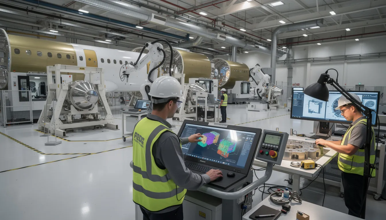
    The image depicts an aerospace manufacturing facility bustling with workers operating precision equipment, showcasing a blend of advanced technology and industrial automation. The environment highlights the importance of reliable data exchange and the integration of OPC UA protocols for effective communication within industrial systems.

    OPC UA and Aerospace/MRO Digital Operations (Connect981 Perspective)

    Aerospace manufacturing and MRO operations depend on precise traceability, structured documentation, and consistent quality records across factories and suppliers. Serial numbers, batch data, repair histories, and inspection results must be accurate, accessible, and auditable. The regulatory environment, including AS9100, NADCAP, and FAA requirements, makes this non-negotiable.

    We see OPC UA’s standardized information models as a stable way to represent machine states, process parameters, measurements, and asset identifiers. When test cells, assembly equipment, and inspection stations expose their data through OPC UA, we can consume that data and relate it to work orders, build packages, and inspection records within our platform.

    In our view, OPC UA is one of the key mechanisms for bridging operational technology data with higher-level systems like ERP, PLM, and QMS. Connect981 focuses on creating that unified operations layer, linking shopfloor execution, supplier workflows, and compliance documentation. We rely on standards like OPC UA to bring structured, vendor-neutral equipment data into that environment without forcing custom integrations for every asset.

    This approach offers several practical advantages:

    • Reduced reliance on custom integrations and spreadsheets for data acquisition
    • Support for AS9100 and regulatory evidence chains through consistent data capture
    • Easier comparison of performance and quality indicators across sites and suppliers
    • Long-term data continuity as equipment and software evolve over decades

    We do not claim that OPC UA alone solves interoperability challenges. The value comes from pairing the standard with domain-specific platforms and operational design that understand aerospace realities.

    Conceptual Benefits of OPC UA-Driven Interoperability

    Standardized, vendor-neutral data exchange can make it easier to integrate new assets, evolve system architectures, and maintain long-term compatibility in changing industrial landscapes. These are conceptual enablers, not guaranteed outcomes.

    Potential benefits:

    Area

    Conceptual Advantage

    Integration

    Easier to add new equipment or software without redesigning interfaces

    Architecture

    Flexibility to evolve systems over time without vendor lock-in

    Communication

    Clearer data exchange between engineering, operations, IT, and suppliers

    Analysis

    Better-aligned data supports more reliable reporting and decision-making

    Longevity

    Standards outlive individual product versions and hardware generations

    Consistent information models support clearer communication by giving all parties a shared view of what data means. When a production engineer, an IT analyst, and a supplier quality manager all reference the same structured data, misinterpretation decreases.

    Better-aligned data from equipment and industrial systems can support more reliable analysis, real time monitoring, and predictive maintenance. Combined with workflow platforms and analytics tools, this data becomes actionable rather than dormant.

    Actual results depend on design choices, implementation quality, change management, and how organizations align OPC UA with existing processes and governance. OPC UA offers an architectural building block for future-ready industrial operations, not a standalone solution. The standard provides increased efficiency and valuable insights only when paired with thoughtful deployment.

    Looking Ahead: OPC UA in the Broader Interoperability Landscape

    The trajectory for OPC UA points toward continued expansion and refinement. Ongoing developments include expanded companion specifications for new domains, harmonization efforts across industries, and growing use of OPC UA in conjunction with message brokers, edge computing, and cloud-native architectures.

    Emerging trends:

    • Integration with time sensitive network for deterministic communication
    • Functional safety extensions for safety-critical applications
    • Expanded models for process industry and discrete manufacturing
    • Alignment with edge devices and cloud-native patterns

    As factories and MRO networks become more distributed and data-centric, OPC UA’s role as a neutral, model-driven exchange layer is likely to remain relevant. Transport technologies and computing platforms will evolve, but the need for consistent data models and reliable communication will persist.

    Governance matters. Organizations that benefit most from OPC UA-based interoperability will need clear ownership of information models, versioning policies, and cross-site conventions. Without this governance, the technical capability of the standard can be undermined by organizational fragmentation.

    OPC UA provides a common conceptual framework for industrial data, one that, when combined with platforms like Connect981 and thoughtful operational design, can support long-lived, adaptable, and auditable industrial ecosystems. For aerospace operations where compliance, traceability, and multi-site coordination are daily realities, this foundation is increasingly essential.

    For organizations looking to connect shopfloor data with work instructions, quality records, and supplier workflows in a structured, vendor-neutral way, exploring how these standards integrate with a unified operations platform is a practical next step. Request a demo to see how Connect981 approaches this challenge.

  • Drill-down

    Drill-down commonly refers to navigating from a high-level summary into progressively more detailed information. In manufacturing and industrial software, it is used to investigate a metric, event, record, or exception by moving from dashboards or aggregated reports into the underlying data.

    The term usually applies to reporting, analytics, MES, ERP, quality, and traceability systems. For example, a user might drill down from plant-level throughput to a production line, then to a work order, and then to a specific machine event or operator entry. The core idea is structured detail navigation, not just opening another screen.

    Drill-down includes hierarchical or linked exploration of related data, such as moving from:

    • a KPI to the transactions or events behind it
    • a nonconformance count to individual NCR records
    • a batch summary to lot, material, or genealogy details
    • an equipment alarm total to time-stamped alarm history

    It does not usually mean root cause analysis by itself, although drill-down is often a step used during investigation. It also does not necessarily imply write access or workflow action; many drill-down paths are read-only views for analysis and verification.

    Common confusion

    Drill-down is often confused with filtering, sorting, and search. Filtering narrows a data set by conditions. Sorting changes display order. Search locates matching records. Drill-down specifically means moving from summary information to the lower-level details behind that information.

    It can also be confused with traceability. Traceability focuses on lineage and relationships across materials, processes, and records. Drill-down is a navigation method that may be used to access traceability data, but it is not the same concept.

    How it appears in operations systems

    In regulated and quality-sensitive environments, drill-down is commonly used to review exceptions, reconcile data between systems, and inspect evidence behind reported metrics. Typical examples include moving from an ERP production summary into MES execution records, or from a quality dashboard into inspection results, deviations, or CAPA-linked records.

  • Model card

    A model card is a structured document that summarizes what an artificial intelligence or machine learning model is, what it was designed to do, how it was evaluated, and what limits or risks should be understood before use. It commonly refers to a human-readable description that travels with the model or is linked to it in a repository, application, or governance workflow.

    In industrial and regulated environments, a model card is typically used as supporting documentation for transparency and internal review. It can help teams understand the model’s purpose, input and output expectations, training or reference data characteristics at a high level, performance measures, known constraints, and operational assumptions. It is documentation about the model, not the model itself.

    What it usually includes

    • The model’s name, version, and owner or maintaining team

    • Intended use cases and users

    • Out-of-scope or prohibited uses

    • Input data expectations and output format

    • Summary of how the model was trained or configured

    • Evaluation approach and reported performance metrics

    • Known limitations, failure modes, or bias considerations

    • Operational dependencies such as data quality, thresholds, or human review requirements

    How it appears in operations

    Model cards often appear in AI governance records, MLOps repositories, validation packages, supplier documentation, or approval workflows tied to analytics and decision-support tools. For example, a manufacturer using a machine learning model for visual inspection or maintenance prediction may keep a model card alongside version-controlled deployment records so quality, engineering, and IT stakeholders can review the model’s stated purpose and limits.

    Common confusion

    A model card is often confused with related artifacts, but they are not the same:

    • Data sheet or dataset documentation: describes the dataset rather than the model.

    • System documentation: covers the broader application, workflow, or architecture, not just the model.

    • Validation report: provides evidence from testing or qualification activities, while a model card is a summary-oriented description.

    • Algorithm specification: may describe logic or mathematics in depth, whereas a model card is usually broader and more operational.

    Boundary of the term

    The term commonly refers to documentation for AI or machine learning models, including predictive, classification, detection, or generative models. It does not by itself imply regulatory approval, production readiness, cybersecurity assurance, or fitness for a specific quality-critical decision. Those determinations depend on the surrounding governance, validation, and operational controls.

  • API-based KPI access

    API-based KPI access commonly refers to the ability to retrieve key performance indicator data through an application programming interface (API) rather than only through dashboards, spreadsheets, or manual exports. In manufacturing and regulated operations, this usually means systems such as MES, ERP, quality, historian, or analytics platforms expose KPI values, counts, rates, or trends in a machine-readable form for other software to consume.

    The term includes both direct access to calculated KPIs and access to the underlying operational data used to calculate them, depending on how a system is designed. It does not by itself mean that the KPI definitions are standardized, that the data is real-time, or that different systems calculate the same metric in the same way.

    Where it applies

    API-based KPI access appears in workflows where performance data needs to move between systems, teams, or reporting layers. Examples include pulling scrap rate from MES into an enterprise analytics tool, reading schedule attainment from ERP into a plant dashboard, or exposing quality trend data to a reporting application.

    • Operational dashboards and BI tools
    • MES and ERP integration
    • Quality and compliance reporting
    • Data lakes, analytics platforms, and custom applications
    • Cross-site or enterprise performance rollups

    What is typically exposed

    Depending on the platform, API-based KPI access may provide:

    • Current KPI values such as OEE, yield, scrap rate, downtime, or on-time completion
    • Time-series KPI history by shift, work order, line, machine, or site
    • Dimensions and filters such as product, operation, lot, or date range
    • Metadata such as units, timestamps, calculation windows, and data source references

    Common confusion

    API-based KPI access is often confused with KPI visualization. A dashboard shows KPIs to a person, while an API exposes KPI data to another system or script.

    It is also different from general data integration. Data integration may move raw transactions, events, or master data; API-based KPI access is specifically about making performance indicators available programmatically.

    Another point of confusion is real-time access. An API can expose near-real-time, batch-refreshed, or historical KPI data. The term does not guarantee update frequency.

    Operational meaning

    In practice, API-based KPI access supports automated retrieval of operational signals without relying on manual extraction. In regulated manufacturing, this matters when KPI data is reused across reporting, investigations, quality review, or performance monitoring processes, because the source system, timestamps, and calculation logic may need to be understood clearly even when the API access itself is technically simple.

  • RAMI 4.0 Reference Architecture: A Structured Explanation

    RAMI 4.0 Reference Architecture: A Structured Explanation

    Overview: What RAMI 4.0 Represents

    RAMI 4.0, the Reference Architectural Model for Industry 4.0, was initially standardized as DIN SPEC 91345:2016 and later aligned with IEC PAS 63088. It emerged from German industry efforts to provide a structured way of describing the components, relationships, and data flows that characterize modern manufacturing systems. The model is a conceptual, three-dimensional reference architecture, not a concrete system blueprint or implementation method.

    The purpose of RAMI 4.0 is to serve as a shared mental model and common language for describing Industry 4.0 systems, physical assets, and data flows across disciplines. Engineers, software vendors, automation specialists, and standards bodies can use the same coordinate system to discuss where a given technology, standard, or function belongs within a broader manufacturing context. This is particularly valuable in environments where information technology and operational technology must converge.

    The model helps position technologies such as digital twin implementations, OPC UA communication protocols, and smart sensors within a consistent architectural frame. However, RAMI 4.0 remains technology-agnostic. It does not mandate specific products, platforms, or integration patterns. This article is written from Connect981’s perspective as an aerospace and MRO operations platform, using RAMI 4.0 purely as a reference explanation without prescribing adoption or implementation steps.

    The image depicts a modern industrial factory floor featuring robotic arms and various automation equipment, illustrating the principles of smart manufacturing and industrial automation. This environment reflects the integration of emerging technologies and communication protocols within the framework of the RAMI 4.0 reference architecture, emphasizing efficiency in manufacturing processes.

    Industry 4.0 Context and Motivation

    The term Industry 4.0 situates current manufacturing transformation within a historical sequence. The First Industrial Revolution brought mechanization through water and steam power. The Second introduced mass production and electrical engineering. The Third applied electronics and information technology to automate industrial processes. The fourth industrial revolution, emerging around 2011 onward, centers on cyber physical systems, the Industrial Internet of Things, and data-driven automation.

    Germany’s “Plattform Industrie 4.0” served as a central driver for this movement. The initiative brought together representatives from mechanical engineering, electrical engineering, and information and communication technology sectors to define a coherent vision for networked production. The goal was not merely to introduce advanced technologies but to enable manufacturing companies to operate with greater efficiency through connected, intelligent systems.

    The complexity of heterogeneous technologies, standards, and domains made a reference architecture necessary. Enterprise IT systems, shopfloor control systems, field devices, and products each brought their own conventions and protocols. Prior models like ISA-95 and IEC 62264 addressed automated interfaces between enterprise and control systems. Life cycle management standards such as IEC 62890 covered industrial system lifecycles. However, neither offered a unified view of Industry 4.0 that could span all these concerns.

    For sectors like aerospace manufacturing and MRO, clear reference models help reason about traceability, digital documentation, and multi-tier supply chain integration. Even if RAMI 4.0 itself does not dictate concrete automation solutions, it provides a vocabulary for discussing where different systems and functions belong in a broader architecture.

    Origins and Standardization of RAMI 4.0

    The development of RAMI 4.0 began around 2013-2015 through the collaborative efforts of German “Plattform Industrie 4.0” working groups, together with VDI (Association of German Engineers) and ZVEI (the German Electrical and Electronic Manufacturers Association). These organizations recognized that without a common framework, Industry 4.0 efforts would fragment into incompatible implementations.

    Key milestones in the standardization process include:

    Milestone

    Year

    Significance

    Initial RAMI 4.0 concept publication

    2015

    ZVEI status report establishing the three-dimensional model

    DIN SPEC 91345

    2016

    German national standard formalizing RAMI 4.0

    IEC PAS 63088

    2017

    International alignment through IEC Publicly Available Specification

    The purpose of RAMI 4.0 from the outset was to harmonize existing and emerging standards, not to replace them. The model gives stakeholders a shared three-dimensional map for positioning international standards and use cases. Government-backed initiatives in Germany aimed to avoid fragmentation by promoting RAMI 4.0 as a common reference, especially for machine builders, automation vendors, and software providers.

    The industrial internet reference architecture (IIRA), developed by the Industrial Internet Consortium, emerged in parallel for broader IIoT contexts. RAMI 4.0 focused specifically on manufacturing and industrial production, reflecting its German manufacturing origins and strong anchoring in European standardization for various industries.

    RAMI 4.0 as a Three-Dimensional Reference Architecture Model

    RAMI 4.0 uses a three dimensional coordinate system to map any Industry 4.0 concept, component, or function. The three axes are:

    • Layers (vertical axis): Representing IT representation of assets
    • Life Cycle & Value Stream (horizontal axis): Representing evolution over time
    • Hierarchy Levels (depth axis): Representing scale from products to connected enterprises

    The visual mental model resembles a three dimensional layer model or grid. Any element can be located by specifying its coordinates on these axes. A sensor’s OPC UA communication function at the work center level during the production phase occupies a specific position within this coordinate system, distinct from an enterprise planning function at the business layer during the design phase.

    The image depicts an abstract three-dimensional grid structure that illustrates a coordinate system with multiple intersecting planes, representing a complex framework for industrial internet reference architecture. This visual metaphor captures the integration of different systems and layers, essential for smart manufacturing and digital transformation in the context of industry 4.0.

    The axes are grounded in existing international standards. The Layers axis arises from IT architecture practice. The Life Cycle & Value Stream axis builds on IEC 62890 principles for life cycle and value chain management. The Hierarchy Levels axis extends IEC 62264 and ISA-95 automation levels, adding a “Product” level at the bottom and “Connected World” at the top.

    The model is descriptive and classificatory. It helps organize thinking and documentation in a structured manner, but it does not prescribe how to build software, design networks, or select technologies. In Connect981’s context, RAMI 4.0 serves as a reference lens to discuss where functions like digital work instructions, traceability, and supplier collaboration would sit in a broader Industry 4.0 architecture.

    Axis 1: Layers (Vertical IT Representation)

    The Layers axis, sometimes called the vertical axis or left horizontal axis in certain visualizations, decomposes how a physical asset is represented and handled in IT systems. The progression moves from physical properties up through data management and business processes. RAMI 4.0 defines six layers, each with distinct responsibilities.

    Asset Layer

    The asset layer focuses on physical entities. These include machines, fixtures, tools, and products with their mechanical and electrical characteristics. In aerospace manufacturing, this might include a serialized composite part, a torque-controlled assembly tool, or a CNC machine. The layer encompasses the physical world, including metal parts, circuit diagrams, QR codes, and documents that represent tangible reality.

    Integration Layer

    The integration layer couples physical assets to the digital world. This is where sensors, controllers, fieldbus interfaces, and initial data acquisition mechanisms reside. For assets that cannot communicate on their own, such as human operators or purely mechanical components, the integration layer provides interfaces like HMIs or barcode scanners. The digital twin concept begins here, creating IT representation of physical assets.

    Communication Layer

    The communication layer provides standardized communication protocols and services for interoperable data transport. Examples include OPC UA, MQTT, and fieldbus gateways. This layer ensures that communication technology enables different systems to exchange data in common formats, regardless of vendor or origin.

    Information Layer

    The information layer structures, contextualizes, and assigns semantic meaning to raw communication data. Data management practices ensure consistent interpretation across systems. Quality attributes, maintenance histories, and production parameters receive formal definitions at this level, supporting semantic interoperability essential for smart manufacturing.

    Functional Layer

    The functional layer defines services, logic, and behaviors. Functions like routing selection, condition monitoring, predictive maintenance rules, and quality check logic reside here. Formal function descriptions support decision logic execution and service-oriented architecture patterns.

    Business Layer

    The business layer models organizational business processes, compliance rules, and economic decisions. In aerospace contexts, requirements from AS9100, FAA, or ITAR regulations would be represented at this level. The layer links manufacturing processes to legal, regulatory, and business objectives, operating above purely technical implementation.

    The Layers axis separates concerns, allowing standards and solutions to focus on specific layers while still fitting into a coherent whole. This supports loose coupling between layers while maintaining high cohesion within each layer.

    Axis 2: Life Cycle & Value Stream (Horizontal Development and Operation)

    The right horizontal axis, or Life Cycle & Value Stream axis, captures an asset’s evolution over time. It spans from initial concept through end-of-life and distinguishes between “Type” and “Instance” perspectives.

    Type Perspective

    The Type perspective addresses generic product definitions, master data, and design models handled before any specific physical instance exists. In aerospace, this might include:

    • A generic engine bracket specification with defined tolerances
    • Master work instructions for a recurring assembly process
    • Design models for prototype production before first article inspection

    Type information represents blueprints and templates that define what something should be.

    Instance Perspective

    The Instance perspective tracks concrete physical items, batches, or machines once produced and deployed. This includes:

    • Serial numbers for individual components
    • Maintenance records for specific engines
    • Modification histories for a particular aircraft

    Instance information represents specific realizations of Type definitions.

    IEC 62890 provides the foundational standard for life cycle management. RAMI 4.0 overlays Industry 4.0 concepts, such as digital twins, onto this time dimension. The axis also encompasses value stream staging from development and prototyping through production, operation, service/maintenance, and decommissioning.

    For aerospace and MRO operations, this distinction matters when discussing traceability. First article inspection relates to validating that an Instance meets its Type definition. MRO overhaul processes track Instance-specific histories against Type-level requirements. The axis does not define individual process steps but provides a comprehensive framework for discussing which life cycle phase a given function or data set relates to.

    Axis 3: Hierarchy Levels (Depth Across Industrial Scale)

    The left horizontal axis represents hierarchy levels, expanding traditional automation levels from IEC 62264 and ISA-95 to reflect modern, connected manufacturing environments. Where traditional models stopped at the enterprise level, RAMI 4.0 extends in both directions.

    Level

    Description

    Aerospace Example

    Product

    Smart products or parts with embedded identification

    Serialized aerospace component with RFID tag

    Field Device

    Sensors, actuators, and drives interacting with physical processes

    Torque sensors on assembly tools, temperature probes in curing ovens

    Control Device

    PLCs, CNC controllers, motion controllers orchestrating field devices

    CNC controller for a 5-axis milling machine

    Station

    Individual machines, workstations, or inspection cells

    Assembly station, automated optical inspection cell

    Work Centers

    Collections of stations forming process areas

    Composite layup area, wing assembly line segment

    Enterprise

    ERP, PLM, and corporate planning systems

    Multi-site production planning, quality management systems

    Connected World

    External networks including customers, regulators, and suppliers

    Supplier data portals, regulatory submission systems

    The “Product” level at the bottom is a significant extension from traditional ISA-95. It recognizes that smart products can actively influence manufacturing processes through embedded sensors or self-optimizing capabilities. This reflects the industrie 4.0 vision where products carry their own production requirements and quality data.

    The “Connected World” level at the top extends beyond enterprise boundaries. In aerospace, this includes interactions with customers, regulatory bodies, and multi-tier suppliers through standards-based interfaces and shared services. The hierarchy levels represent the spectrum from individual components to global supply chain ecosystems.

    Unlike rigid pyramidal hierarchies of earlier models, RAMI 4.0 assumes cross-level communication and more dynamic interactions. Components at any level can potentially communicate with other components, supporting the network-structured architectures that characterize smart factories.

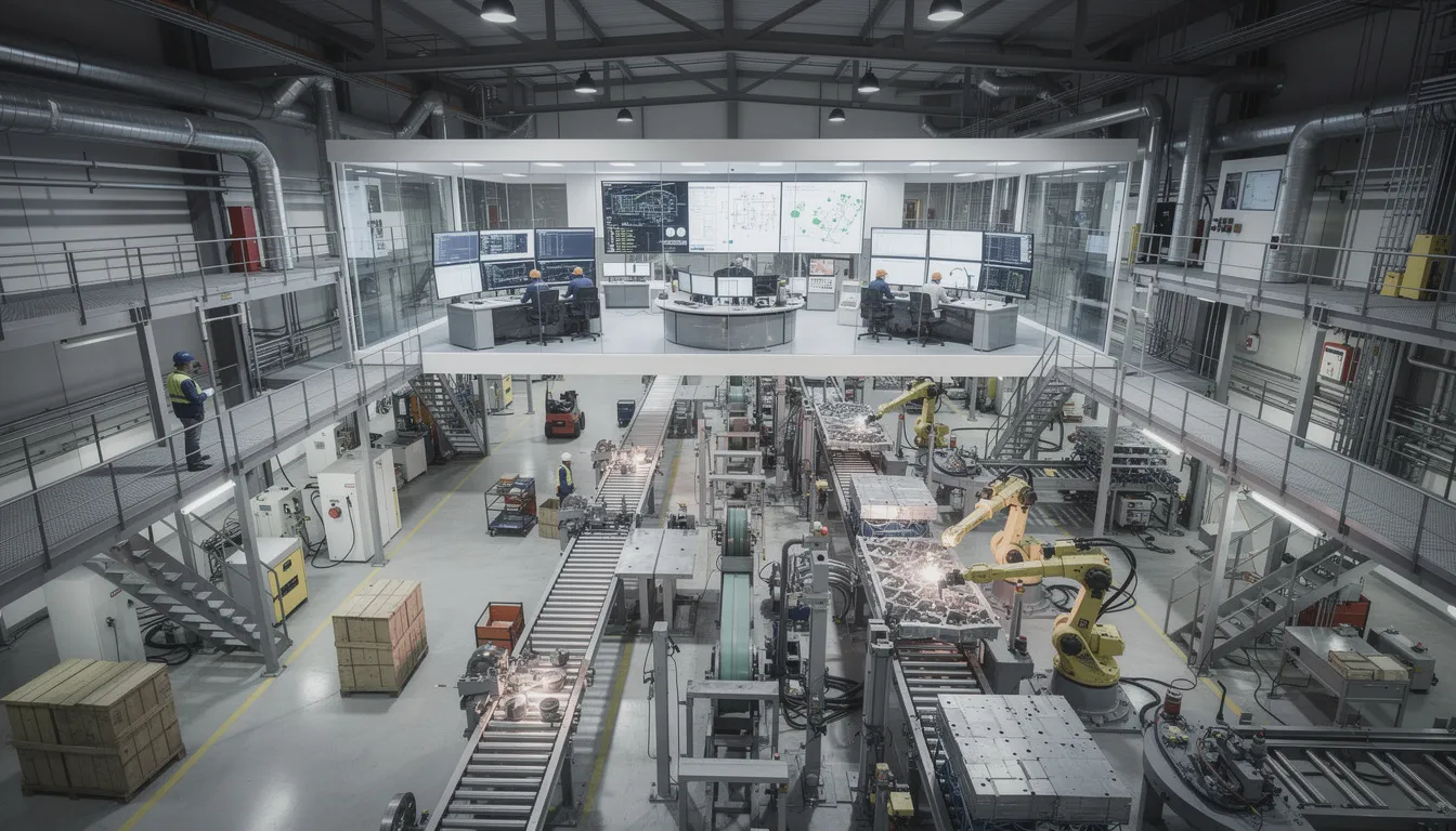
    The image depicts a large industrial manufacturing facility showcasing multiple operational levels, from floor equipment to control rooms, illustrating the integration of advanced technologies and automation solutions in a smart manufacturing environment. This scene represents the principles of the RAMI 4.0 reference architecture, highlighting the importance of communication technology and data management in optimizing industrial processes.

    Purpose and Use of Reference Architecture Models in Industry 4.0

    A reference architecture model is an abstract, standardized way of describing system structures and relationships, independent of particular products. Reference models serve several important aspects in complex systems environments.

    Shared Vocabulary

    Reference architectures provide a neutral, agreed-upon terminology for engineers, software vendors, and policy makers. When stakeholders discuss “where” a function belongs, a reference model gives them common understanding. The hierarchy levels, layers, and life cycle phases provide a structured approach for cross-disciplinary dialogue.

    Classification

    Existing standards, technologies, and use cases can be mapped to specific segments of the model. This clarifies where overlaps or gaps exist. For example, OPC UA clearly maps to the Communication layer, while IEC 62890 informs the Life Cycle axis. This classification supports step by step migration from legacy systems to smart manufacturing environments.

    Alignment

    In complex, multi-partner ecosystems such as aerospace value chain networks, different stakeholders need common perspective on system architecture. A reference model helps align expectations and documentation without requiring every party to use identical products or platforms.

    Analysis

    Systematic analysis becomes possible by locating elements along the three axes and assessing interactions or dependencies. Questions like “what happens when a field device needs to communicate with enterprise systems?” can be discussed using the model’s structure.

    Reference architectures like RAMI 4.0 do not mandate specific products, communication protocols, or platforms. They provide a standardized framework into which solutions can be placed. For platforms like Connect981, reference models inform conceptual discussions about where digital work instructions, traceability functions, or supplier collaboration portals sit in relation to broader Industry 4.0 structures.

    RAMI 4.0 in Relation to Other Industry 4.0 Architectures

    Multiple reference models coexist in the Industry 4.0 landscape. Understanding their relationships helps clarify RAMI 4.0’s specific focus.

    The Industrial Internet Reference Architecture (IIRA), developed by the Industrial Internet Consortium, is domain-independent. It covers a broad range of IIoT use cases beyond manufacturing, including energy, transportation, and healthcare. The IIRA addresses a connected world of industrial applications without the specific manufacturing focus of RAMI 4.0.

    Aspect

    RAMI 4.0

    IIRA

    Primary Focus

    Manufacturing, industrial production

    Broad IIoT across sectors

    Geographic Origin

    Germany, European standardization

    International, US-based consortium

    Life Cycle Integration

    Explicit axis based on IEC 62890

    Less explicit lifecycle dimension

    Hierarchy Model

    Extended ISA-95 with Product and Connected World

    Different functional domains approach

    International organizations have also developed related frameworks. NIST’s CPS Framework addresses cyber physical systems more broadly. Sector-specific models exist for particular industries. Sometimes mappings are created to translate between these architectures.

    Multiple reference models can be used in parallel. An organization might use IIRA for high-level IIoT planning and RAMI 4.0 to describe detailed manufacturing asset interactions. These models are abstract tools for structuring thought and documentation rather than prescriptive roadmaps for digital transformation or technology selection.

    Conceptual Strengths and Limitations of RAMI 4.0

    Strengths

    RAMI 4.0 provides several conceptual benefits:

    • Systematic Structure: The three-axis approach forces stakeholders to specify where, in terms of layers, life cycle phases, and hierarchy levels, a given concept belongs
    • Standards Grounding: Building on established IEC standards gives the model credibility and integration with existing industrial process measurement and automation frameworks
    • Cross-Disciplinary Dialogue: IT, OT, and business stakeholders can use the same coordinate system to discuss complex systems
    • Neutral Framework: Technology-agnostic positioning allows the model to remain relevant as emerging technologies and artificial intelligence capabilities evolve

    Limitations

    Any architectural abstraction carries inherent limitations. RAMI 4.0 is no exception.

    Abstraction Gap: High-level models cannot capture all real-world constraints. Legacy system quirks, specific aerospace regulations, organizational culture, and machine learning integration challenges do not map neatly onto a three-dimensional cube. The gap between model and reality requires additional guidance.

    Static Representation: The model is largely static and structural. Industry 4.0 systems often exhibit dynamic, adaptive behaviors. Real-time reconfiguration, autonomous decision-making by control systems, and event-driven architectures are difficult to express in a static coordinate system.

    Interpretation Variability: Organizations may interpret axes and levels differently. What one company considers a “Work Center” another might classify as a “Station.” This leads to inconsistent mappings and the need for supplementary documentation.

    Scope Boundaries: RAMI 4.0 focuses on industrial production. It does not, by itself, fully address service operations, logistics networks, or detailed cybersecurity models. Other components of a complete Industry 4.0 strategy require additional frameworks.

    RAMI 4.0 should be seen as one analytical lens among several. It structures discussions and documentation effectively but is insufficient on its own to fully specify or guarantee a working Industry 4.0 system. The model identifies where standards and business models might apply but does not resolve all practical challenges of integration.

    Implications for Digital Industrial Operations (Without Prescriptive Guidance)

    For domains like aerospace manufacturing and MRO, a model like RAMI 4.0 can inform thinking without dictating solutions.

    The Layers axis offers a way to discuss where capabilities typically reside:

    • Digital work instructions might span the Information and Functional layers, providing structured data with associated business logic
    • Traceability functions operate across Integration, Information, and Business layers, linking physical assets to semantic data and compliance requirements
    • Quality checks engage Functional layer logic with Business layer rules

    The Life Cycle & Value Stream axis clarifies whether a given data set or function relates to Type or Instance information. Tracking serialized aerospace components across manufacturing and MRO requires distinguishing between master definitions and instance-specific histories. This distinction matters for data management strategies and audit requirements.

    The Hierarchy Levels axis provides vocabulary for indicating whether a function pertains to field devices, stations, work centers, or enterprise and connected world levels. Multi-site coordination and supplier collaboration involve enterprise and connected world interactions, while shopfloor execution focuses on station and work center levels.

    The image depicts an aerospace manufacturing environment where workers are actively operating advanced equipment amidst digital displays on the factory floor, highlighting the integration of emerging technologies and industrial automation in smart manufacturing processes. This setting reflects the principles of the RAMI 4.0 reference architecture, emphasizing life cycle management and data management in a connected world.

    For platforms like Connect981, RAMI 4.0 acts as a reference backdrop for analysis and communication with stakeholders. When discussing how digital work instructions, traceability, and supplier portals function, the model provides a common language. However, the model does not directly define software modules, integration patterns, or deployment approaches.

    RAMI 4.0 is most valuable as a conceptual reference architecture. It structures how Industry 4.0 scenarios are described and reasoned about in various industries. Practical system design requires additional, more detailed models and decisions beyond the scope of what any single reference architecture can provide. For aerospace and MRO organizations navigating Industry 4.0 concepts, the model offers a starting point for structured discussions rather than a destination.

    For organizations seeking practical aerospace operations platforms that address shopfloor execution, traceability, and supplier collaboration, Connect981 offers a demo to explore how these capabilities work in real manufacturing environments.