RSC Sphere: Quality, Compliance and Traceability

The Quality, Compliance and Traceability Sphere demonstrates how audit-grade credibility is built directly into execution workflows. It connects nonconformance, corrective action, inspection, traceability, and audit evidence into a continuous operational loop. The content emphasizes how quality systems must interact with live work rather than exist as parallel documentation processes. This sphere proves that compliance and execution can reinforce each other instead of competing for attention.

  • How do we handle nonconformities that affect both quality and security?

    Handle nonconformities that affect both quality and security as a single, linked issue that is processed through both your quality management and cybersecurity processes. Splitting them into separate tracks without coordination usually creates gaps in risk assessment, corrective actions, and evidence for audits.

    1. Establish clear criteria for “quality + security” nonconformities

    First define what qualifies as a joint issue in your context. Typical triggers include:

    • Product or process nonconformance that is suspected to be caused by a cyber incident (e.g., tampered parameters, manipulated test results, unauthorized MES changes).
    • Security incidents that may have altered manufacturing records, recipes, configurations, or evidence needed for product release or traceability.
    • Compromise of systems that are part of validated or qualified processes (e.g., MES, historians, QMS, equipment controllers) where integrity of quality data is uncertain.

    The exact criteria depend on your risk assessment, system landscape, and regulatory obligations. Document them in procedures so operations, quality, and IT/OT security interpret events consistently.

    2. Use a single master record with cross-links to QMS and security

    In brownfield environments, you typically will not have a single system that can cleanly own both quality and security workflows. Instead:

    • Create one master record in the system that has the strongest regulatory traceability requirements, usually the QMS (e.g., nonconformity or CAPA record).
    • Open a corresponding security/incident ticket in the corporate incident response tool or OT security system.
    • Link the records explicitly using IDs in both directions and reference them in deviation reports, risk assessments, and change control.

    Do not rely only on email or informal notes for these links. The master record should clearly state that security and data integrity are in scope so reviewers can see the full context.

    3. Run a joint impact and risk assessment

    Assess impact across both quality and security dimensions before deciding on containment or release decisions.

    At minimum, consider:

    • Product and patient/customer impact: Could altered data or process steps affect safety, performance, regulatory compliance, or field reliability?
    • Data integrity: Are historical records, batch data, test results, or genealogy still trustworthy? How far back could compromise extend?
    • System scope: Which systems (MES, PLCs, DCS, LIMS, QMS, ERP) may have been affected? Are any validated or qualified?
    • Regulatory and contract requirements: Are there obligations to notify regulators, certification bodies, or customers for security-related quality risks?
    • Containment risk: Could security containment actions (e.g., isolating a line, blocking accounts, patching) create new process or quality risks?

    This assessment should be performed collaboratively by quality, operations/engineering, and IT/OT security, not by one function alone.

    4. Coordinate containment across production, quality, and IT/OT

    Containment must limit both quality and security impact, while recognizing constraints on downtime and validation:

    • Stabilize the process: Pause affected lots/batches, label and segregate suspect material, and freeze product release decisions until minimum integrity is established.
    • Secure the environment: IT/OT may isolate systems, disable accounts, or roll back configurations, but should coordinate with operations to avoid unsafe or uncontrolled shutdowns.
    • Preserve evidence: Ensure logs, configuration snapshots, and relevant batch records are preserved before systems are rebuilt or restored.

    Document containment decisions and tradeoffs, especially if security best practices must be staged or adapted to avoid unplanned outages of validated systems.

    5. Perform integrated root cause analysis

    Root cause analysis should explicitly consider both process/quality and cybersecurity contributing factors. Common patterns include:

    • Process & equipment: Poor parameter control, inadequate verification of setpoints, missing independent checks.
    • Human factors: Shared credentials, bypassed controls, unvetted changes to master data or recipes.
    • Technical controls: Inadequate network segmentation, weak access control, insufficient integrity monitoring, missing change logs.
    • Management systems: Gaps in training, procedures, and change control covering both quality and security for OT systems.

    If you use formal methods (e.g., 5-Whys or fishbone diagrams), show explicitly where security-related causes and controls come into play. This is important for auditability and for preventing recurrences that cross domains.

    6. Design CAPAs that address both domains

    Corrective and preventive actions must be coherent across quality and security. Typical actions might include:

    • Process corrections: Rework, additional inspection, or product recall decisions based on validated data integrity and risk criteria.
    • Security hardening: Strengthening authentication, tightening change control on recipes/configurations, improving logging, or implementing OT security monitoring.
    • Data integrity measures: Rebuilding trust in data sets (e.g., re-running critical tests, cross-checking manual records, reconciling batch histories).
    • Governance changes: Updating procedures to require security review for changes to validated systems, training operators and engineers on cyber-impacted nonconformities.

    Be explicit about which system owns each action (QMS, ITSM, OT maintenance system, MES change workflow) and ensure due dates and effectiveness checks are aligned. Avoid duplicating the same action in multiple systems without synchronization.

    7. Respect validation, change control, and legacy system constraints

    In regulated, long-lifecycle plants, many quality-critical and OT systems are validated or qualified, and cannot be rapidly replaced or heavily modified without significant cost and downtime. When handling joint quality/security nonconformities:

    • Expect that “ideal” security fixes (e.g., rapid patching, architecture overhauls, replacing legacy controllers) may not be immediately feasible for validated equipment and software.
    • Use layered mitigations where needed, such as procedural controls, monitoring, or network-level protections, while planning longer-term validated changes.
    • Ensure any configuration change, patch, or system restoration follows documented change control and, where required, revalidation or verification.

    Full system replacement solely to resolve a combined quality/security issue is rarely practical in aerospace-grade or similarly regulated environments, due to qualification burden, revalidation cost, integration complexity, and extended downtime risks. Plan phased, risk-based improvements instead.

    8. Maintain traceability and audit-ready documentation

    Because these events cut across domains, documentation and traceability are critical:

    • Retain a complete chain of records: initial detection, risk assessment, decision logs, containment, root cause analysis, CAPAs, and effectiveness checks.
    • Ensure traceability from affected lots/batches and equipment to the nonconformity, and from the nonconformity to the associated security incident records.
    • Capture rationale for decisions, especially where business continuity or validation constraints limited the speed or scope of security changes.

    This documentation supports regulatory inspections, customer audits, and internal reviews, but it does not guarantee any specific compliance or certification outcome.

    9. Define ownership and communication paths

    Clarity on roles and escalation is essential before an event occurs:

    • Assign a lead function for joint issues, often quality for product-impacting events, with IT/OT security as co-leads for cyber incidents.
    • Predefine when to involve site management, corporate security, legal, and regulatory affairs.
    • Ensure operators and engineers know how to recognize and report issues that may have a security origin (e.g., unexplained parameter changes, inconsistent MES data).

    Periodic drills or tabletop exercises that include both nonconforming product scenarios and security incidents can expose gaps in your current approach.

    10. Fit the approach to your existing systems and maturity

    The specifics of handling joint quality/security nonconformities depend heavily on:

    • Which systems you have in place (QMS, MES, ERP, ITSM, OT monitoring) and how well they are integrated.
    • Your current validation state, documented procedures, and data integrity controls.
    • The regulatory frameworks and customer expectations that apply to your products and markets.

    Where tooling integration is weak, focus on clearly defined procedures, roles, and record-linking conventions. Over time, you can incrementally improve system integrations to reduce manual effort and the risk of things “falling between” quality and security workflows.

  • AI-assisted root cause analysis

    AI-assisted root cause analysis commonly refers to the use of artificial intelligence techniques to help investigate why a problem occurred in a process, system, or operation. In manufacturing and regulated environments, it is typically used to support analysis of deviations, nonconformances, downtime events, yield loss, alarm patterns, or recurring quality issues by finding patterns, correlations, sequences, or anomalies across available data.

    It is a support method, not the root cause itself and not a guarantee that the suggested cause is correct. The output is usually a ranked set of likely contributing factors, evidence links, or investigation leads that people review alongside process knowledge, documented procedures, and formal quality methods.

    What it usually includes

    • Analysis of data from MES, ERP, QMS, historians, CMMS, SCADA, LIMS, or maintenance logs

    • Pattern detection across events such as scrap spikes, machine faults, parameter drift, changeovers, or supplier-related defects

    • Use of machine learning, statistical models, rules, knowledge graphs, or generative AI to summarize evidence and propose likely causes

    • Tracing possible relationships among materials, equipment states, operators, work orders, batches, or process settings

    What it does not mean

    • It does not replace structured problem-solving methods such as 5 Whys, fishbone analysis, fault tree analysis, or formal RCCA workflows.

    • It does not prove causation simply because it finds correlation.

    • It is not the same as corrective action, CAPA execution, or verification of effectiveness.

    • It is not limited to generative AI chat tools. Many implementations use analytics models or rules engines without a conversational interface.

    How it appears in operations

    Operationally, AI-assisted root cause analysis often appears as a feature in quality, manufacturing, reliability, or analytics software. A system may ingest event records, process parameters, genealogy, maintenance history, and inspection results, then highlight common precursors or probable drivers of an issue. For example, it may associate recurring surface defects with a specific material lot, machine setting range, tool wear pattern, or sequence of alarms before failure.

    In regulated manufacturing, the value of the term usually depends on traceable inputs, retained evidence, and clear distinction between system-generated suggestions and human conclusions.

    Common confusion

    AI-assisted root cause analysis is often confused with predictive maintenance, anomaly detection, or incident summarization. Predictive maintenance focuses on forecasting failures before they occur. Anomaly detection flags unusual behavior. Incident summarization condenses records or logs. AI-assisted root cause analysis is narrower: it focuses on explaining why a specific problem likely happened.

  • false negative

    Core meaning

    In industrial, quality, and monitoring systems, a **false negative** is a test or detection result where a real issue is present, but the system incorrectly indicates that there is no issue.

    Formally:
    – The condition, defect, or event **does exist** in reality.
    – The test, sensor, or alerting logic **fails to flag it** and returns a “negative” or “normal” result.

    False negatives are commonly discussed in:
    – **Condition monitoring and alerts** (e.g., an equipment health alert not firing even though a fault is developing).
    – **Quality inspection and testing** (e.g., a defective part passing inspection as if it were good).
    – **Environmental or safety monitoring** (e.g., a hazardous condition not being detected by the monitoring system).

    Use in industrial and regulated workflows

    Within manufacturing and regulated operations, false negatives typically arise in:

    – **Automated alerting and alarms**
    A sensor or rule-based alert fails to trigger even though process parameters have drifted into a problematic state.

    – **Quality control and release testing**
    A product sample with a nonconformance passes tests and is released as conforming, because the test failed to detect the defect.

    – **Predictive and condition-based maintenance**
    A predictive model indicates that an asset is healthy, but a failure is already developing or imminent.

    – **Data validation and compliance checks**
    A batch record or electronic form contains an error, but automated checks do not detect it and the record is accepted as valid.

    In these settings, false negatives are tracked and analyzed because they can allow unsafe conditions, nonconforming product, or unplanned downtime to progress without intervention.

    Boundaries and what it is not

    – A false negative is **not** the same as:
    – A **true negative**, where the system correctly reports that no issue is present.
    – A **false positive**, where the system signals an issue even though none exists.
    – A **missed event due to no measurement at all** (e.g., no sensor installed, or no test performed). A false negative specifically requires that a measurement or evaluation was made but was inaccurate in the “no issue” direction.

    – The term applies to the **outcome of a specific test, model, or rule**, not to the general reliability of a system. A system may have both false negatives and false positives, and these trade-offs are often managed together.

    Relation to performance metrics

    False negatives are a key component of detection and classification performance, including:

    – **Sensitivity / recall**: the proportion of actual issues that are correctly detected. A higher false negative rate lowers sensitivity.
    – **False negative rate (FNR)**: the number of false negatives divided by the total number of actual issues.

    In manufacturing analytics, engineers and quality teams often review confusion matrices or similar summaries to understand how often systems miss real problems and to compare alternative detection thresholds or models.

    Site context: alerts and operational events

    In the context of alerts intended to prevent operational disruptions (such as line stoppages or critical asset downtime), a **false negative** occurs when:

    – Conditions that should trigger an alert and subsequent action are present, **but no alert is raised** or it is classified as non-critical.
    – The adverse outcome (e.g., an unplanned outage, scrap, or safety incident) occurs without prior warning from the alerting system.

    When analyzing whether alerts are effective, teams look for cases where major events occurred **without** corresponding alerts; these are treated as false negatives of the alerting system and are central to reliability and risk discussions.

    Common confusion

    – **False negative vs. false positive**
    – False negative: real issue, **no** alert or detection.
    – False positive: **no** real issue, but an alert or detection is triggered.

    – **False negative vs. low severity classification**
    Misclassification of severity (e.g., labeling a critical defect as minor) is related but distinct. A strict false negative usually means the system indicates “no issue”; mis-severity is a classification error that may still count as a detection, depending on the analysis framework.

  • return-to-service

    Return-to-service commonly refers to the act of placing equipment, a production asset, a controlled system, or a maintained item back into normal operational use after it was out of service. The term usually implies that required work, checks, approvals, and documentation have been completed to the level defined by the organization’s procedures.

    In industrial and regulated environments, return-to-service is typically used after maintenance, repair, calibration-impacting work, change control activities, deviations, shutdowns, inspections, or corrective actions. It is not the repair or maintenance work itself. It is the transition point at which the item is released for use again.

    What it includes

    The exact steps vary by industry and asset type, but return-to-service often includes confirming that:

    • the required work was completed
    • the asset or system is in its intended configuration
    • necessary inspections, tests, or verification activities were performed
    • any holds, locks, or temporary restrictions were removed through the proper process
    • records were updated in the relevant maintenance, quality, or execution systems
    • an authorized person or function released the item for operation

    Examples include releasing a production line after maintenance, returning a calibrated instrument to use, or restoring an MES-connected workstation after controlled software changes.

    Operational meaning in systems and workflows

    In digital operations, return-to-service may appear as a workflow status, approval step, maintenance closeout event, or release transaction in systems such as EAM, CMMS, MES, QMS, or ERP-integrated maintenance processes. It can be linked to evidence such as work orders, inspection results, deviation records, electronic signatures, or change control references.

    Where traceability matters, organizations often distinguish between a system being technically available and being formally returned to service. A machine may be powered on and runnable, for example, but not yet released for production until all required checks are complete.

    Common confusion

    Return-to-service is often confused with related terms:

    • Restart: restarting means resuming operation, but it does not always imply formal release or documented verification.
    • Commissioning: commissioning applies to bringing new or significantly modified equipment into intended operation. Return-to-service usually applies to something already in service that was temporarily removed.
    • Release: release is broader and may refer to product, batch, software, or document approval. Return-to-service is specifically about restoring operational use of an asset, system, or maintained item.
    • Requalification or revalidation: these are specific verification activities that may be required before return-to-service, but they are not the same thing as the final return-to-service decision.

    Boundary notes

    The term does not by itself define who can authorize the return, what evidence is sufficient, or what standard applies. Those details depend on the asset type, the process risk, internal procedures, and applicable industry requirements. In some sectors, especially maintenance-heavy environments, the term may be used very formally. In others, it may be used more generally to mean restoring operational availability with documented handoff.

  • Aerospace Scrap Reduction: Managing Nonconformance, Margin Risk, and Capacity

    Aerospace Scrap Reduction: Managing Nonconformance, Margin Risk, and Capacity

    Scrap in aerospace manufacturing is not a shopfloor housekeeping issue. It is a program-level financial event with direct consequences for margin, capacity, and contractual performance. When a titanium forging or a machined nickel superalloy component fails inspection late in its routing, the loss extends far beyond material cost. The hours of machining, special processing, and skilled labor invested in that part are gone. The machine capacity consumed cannot be recovered. The delivery slot committed to Boeing or Airbus is now at risk.

    Aerospace programs operate on long timelines, often spanning 10 to 15 years of production. Within those programs, scrap rates compound. A 2% yield loss on a flight-critical subassembly does not stay at 2% in isolation. It displaces capacity needed for on-time new production, drives expedited remake orders, and creates ripple effects across suppliers, inspection queues, and program schedules. For organizations managing multiple programs across multiple sites, these effects multiply further.

    This article provides an executive-level framework for understanding scrap and cost of poor quality in aerospace manufacturing. The goal is not to prescribe a checklist but to offer a structured way of thinking about where scrap originates, how its costs propagate, and what governance and process disciplines protect margin and program performance. Connect981 works with aerospace manufacturing and MRO organizations, so the perspective here is grounded in regulated operations. However, the focus remains on strategy and framework rather than tools.

    Defining Scrap and Nonconformance in an Aerospace Context

    Precision in terminology matters when discussing aerospace scrap reduction. The word “scrap” often gets used loosely, but in regulated aerospace environments, it carries specific meaning within a broader system of nonconformance management.

    Scrap refers to material that cannot be brought into conformance with approved requirements and must be destroyed or disposed of outside the aerospace supply chain. Once a part is scrapped, all invested labor, material, and processing are unrecoverable.

    Rework is the process of bringing nonconforming material into full conformance with the original design requirements through additional processing. A machined dimension that falls slightly outside tolerance may be corrected through additional machining, provided the correction remains within drawing limits.

    Repair differs from rework in that the part is brought to a condition that meets the intended function but does not fully conform to the original design. Repairs require engineering approval and often customer or design authority concurrence.

    Concession (sometimes called a deviation or use-as-is disposition) allows a nonconforming condition to be accepted without correction. This requires formal engineering evaluation and documented approval, typically from the design authority or customer.

    Nonconforming material, in the broader sense, includes any deviation from the approved configuration, drawing, specification, or process plan. A flight-critical turbine blade failing dimensional inspection is nonconforming. A composite spoiler panel with porosity outside specification limits is nonconforming. A fastener lot missing required certifications is nonconforming. The eventual disposition may be scrap, rework, repair, or concession, but the material is nonconforming from the moment the deviation is identified.

    Understanding nonconformance rates requires looking at both part family and process. Special processes such as heat treatment, NDT, plating, and welding often generate characteristic nonconformance patterns that differ from machining or assembly operations. Tracking nonconformance by process family reveals systemic issues that part-level tracking alone may obscure.

    Scrap as a Financial and Program Risk Event

    In aerospace manufacturing, each scrap event is both a financial loss and a program risk event. The financial dimension is visible; the program risk dimension is often underestimated.

    Consider a concrete example. A titanium forging enters the factory with a raw material value of approximately $18,000. By the time it has undergone 40 hours of precision machining and multiple special processes, the invested value may exceed $50,000. If that part fails inspection at a late operation and cannot be reworked, the entire invested value is lost. The material cost is substantial, but the capacity consumed is equally significant. Those 40 machine hours, the skilled labor, the special process slots, and the floor space occupied during work-in-process are unrecoverable. They were consumed producing a part that will never ship.

    This capacity displacement effect is central to understanding aerospace scrap economics. Rework and remake orders compete for the same limited resources needed for on-time new production. When a serialized assembly is scrapped late in its routing, the replacement order does not simply queue behind existing work. It often triggers expedited processing, overtime, and priority scheduling that disrupts the flow of other orders. The true cost includes not only the direct loss but also the indirect impact on overall production efficiency.

    Schedule and delivery risk compounds the financial impact. Aerospace programs operate on tightly coordinated delivery schedules. A scrapped configuration-controlled assembly destined for an Airbus A350 or a Boeing 787 does not merely represent a financial loss. It may jeopardize a contractually committed delivery slot. Missed milestones, whether during CDR, LRIP volume ramps, or retrofit campaigns, can trigger penalties, liquidated damages, or fee-at-risk clauses on performance-based contracts.

    For MRO operations, the dynamics are even more compressed. Scrapping an in-service component during repair can trigger AOG exposure, customer penalties, and unplanned material replacement costs. The timeline for recovery is measured in days rather than weeks, and customer satisfaction depends on timely delivery that scrap events directly threaten.

    The True Cost of Poor Quality in Aerospace Manufacturing

    The classic cost of poor quality framework divides quality costs into four categories: prevention, appraisal, internal failure, and external failure. In aerospace, each category carries specific operational meaning that differs from general manufacturing.

    Prevention costs represent investments made to prevent defects from occurring. In aerospace, this includes defining robust special process controls, training licensed inspectors, developing and qualifying suppliers, conducting detailed Failure Modes and Effects Analyses (FMEAs), and performing process capability studies. Prevention costs are proactive investments that reduce the probability of nonconformance downstream. Organizations that underinvest in prevention often see the consequences surface as chronic yield loss and elevated rework rates.

    Appraisal costs are the expenses incurred to detect nonconformance before it reaches the customer. Aerospace appraisal costs are substantial because of the nature of flight-critical hardware. They include 100% inspection of critical characteristics, first article inspection (FAI) requirements, NDT across multiple methods, functional testing, and the redundant signoffs required by AS9100 and customer quality standards. These costs are necessary but represent resources that do not directly add value to the product.

    Internal failure costs arise when nonconformance is detected before delivery. This category includes scrap, rework, re-inspection, MRB (Material Review Board) activity, engineering dispositions, line stoppages, and expedited remake orders. Internal failures consume capacity, extend lead times, and generate administrative burden. In many aerospace facilities, internal failure costs represent the largest component of COPQ but are often underreported because rework hours and MRB activity are not always tracked as distinct cost categories.

    External failure costs occur when nonconformance escapes to the customer or into service. In aerospace, external failures can be severe: field findings, service bulletins, warranty claims, retrofit campaigns, and in the most serious cases, reportable events to the Federal Aviation Administration or EASA. External failure costs extend beyond direct remediation to include reputational damage, customer relationship strain, and potential regulatory action that affects future business. The safety risks associated with external failures in aerospace mean that even low-frequency events carry disproportionate consequence.

    A critical insight for aerospace executives is that internal failures often mask external risk. Parts “saved” through repair or concession still add lifecycle cost. A component that required multiple engineering dispositions during production may perform adequately in service but represents elevated operational risk and reduced margin. Concession volume is a leading indicator of process capability issues that, left unaddressed, eventually surface as external failures.

    In many mid-size aerospace plants, COPQ silently consumes 3% to 8% of sales revenue. This figure is rarely visible in standard financial reporting because quality costs are distributed across labor, material, and overhead accounts. Making COPQ visible as a distinct metric is a precondition for managing it strategically.

    Aerospace Quality Cost Drivers: Where Scrap Really Starts

    Most aerospace scrap and manufacturing waste originate upstream, in design decisions, process discipline, and configuration control, rather than at final inspection. Understanding where scrap starts is essential for executives who want to target prevention rather than remediation.

    Complex geometries and tight tolerances create inherent process risk. Aerospace components frequently require tolerances that approach the limits of available process capability. When design specifications leave insufficient margin for normal process variation, chronic yield loss becomes inevitable regardless of operator skill or equipment condition. This is a design-manufacturing interface issue that requires early collaboration between engineering and production.

    Late design changes disrupt established processes and introduce new failure modes. A drawing revision late in the production stage may invalidate existing tooling, work instructions, and inspection criteria. The transition period between revisions often generates elevated scrap rates as the production process adjusts to new requirements. Effective change management includes assessing the production impact of design changes before release.

    Inadequate process FMEAs leave potential failure modes unaddressed. When process failure mode analysis is superficial or incomplete, controls are not put in place for high-risk operations. The consequence is that defects are detected only at inspection rather than prevented through process discipline. Process improvement depends on rigorous upfront analysis that anticipates where problems will occur.

    Configuration control issues represent a systemic source of nonconformance. When the wrong revision of a drawing or work instruction reaches the production line, when obsolete specifications are applied, or when software part numbers do not match hardware configurations, systemic scrap results. These are not operator errors but governance failures that affect entire production lots.

    Supplier-related drivers extend the quality cost picture beyond the factory walls. Inconsistent raw material properties, incomplete certification packages, unqualified special process sources at sub-tier suppliers, and poor change control across the supply chain all generate nonconformance that surfaces during receiving inspection or, worse, during production. Supply chain efficiency depends on supplier quality management that extends beyond audit compliance to genuine process capability at source.

    Human factors contribute to quality issues even when processes are well-designed. Overloaded operators, unclear work instructions, ambiguous inspection criteria, and shift-to-shift variation in interpretation all generate inconsistency. Reducing human error requires not only training but also clear, unambiguous work standards that leave minimal room for interpretation.

    A hidden driver of aerospace COPQ is the “heroic recovery culture” that develops in some organizations. When MRB activity, engineering dispositions, and last-minute concessions become routine rather than exceptional, the organization has normalized nonconformance. The costs are absorbed into standard operations and become invisible. Breaking this pattern requires making the cost of recovery visible and shifting investment toward prevention.

    Scrap, Process Capability, and Special Process Control

    Persistent scrap rates often trace back to inadequate process capability and weak control of special processes. In aerospace manufacturing, process capability indices (Cp, Cpk) are not academic exercises but operational predictors of yield and scrap.

    Special processes present particular challenges. Heat treatment, shot peening, NDT, bonding, plating, and welding produce characteristics that are not fully verifiable by subsequent inspection. The material properties imparted by heat treatment, for example, cannot be confirmed by measuring a finished dimension. Process discipline becomes the primary safeguard against nonconformance. When special process controls are weak, defects escape detection until much later in the routing or, in some cases, until service.

    For machining, forming, and composite layup, low process capability translates directly into chronic yield loss. Consider a recurring problem with out-of-tolerance bores on landing gear components. If tool stability is marginal and the process Cpk is below 1.0, the operation will produce 15% to 20% scrap and rework at that step regardless of operator attention. The solution is not additional inspection or operator discipline but addressing the process capability gap through tooling, fixturing, or method changes.

    Complex routings amplify capability issues. When a part passes through multiple special processes and inspections, yield loss at each stage compounds. A 95% yield at each of five sequential operations results in overall yield below 77%. Tracking scrap rates only at final inspection obscures where in the routing the losses actually occur.

    Executives should ensure that yield and scrap are tracked by operation and by process family, not only by finished part number. This visibility enables targeted investment in process optimization, tooling upgrades, and vendor qualification where the impact is greatest. Process capability improvement is a capital allocation decision, not merely a quality function responsibility.

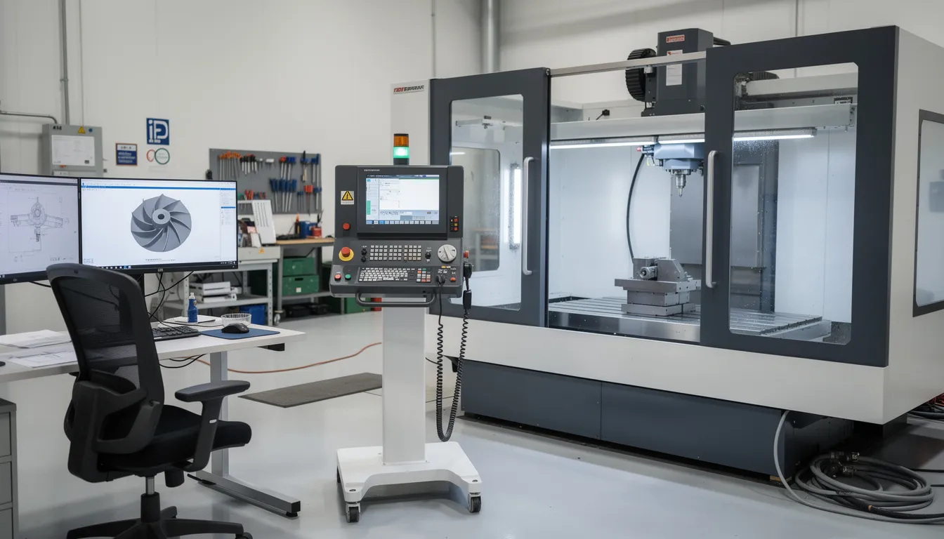
    The image depicts a precision aerospace machining operation focused on a large titanium component, showcasing advanced manufacturing processes in the aerospace industry. This scene emphasizes quality management and operational efficiency, highlighting the importance of consistent quality control and scrap reduction in production.

    Nonconforming Material as a Capacity and Governance Problem

    Nonconforming material control is often treated as a paperwork function, managed by quality specialists and handled through MRB procedures. In practice, NCM control is a capacity and governance discipline that affects flow, inventory accuracy, and compliance posture.

    Uncontrolled NCM creates operational drag. Parts waiting for MRB disposition occupy floor space, tie up WIP inventory, and delay downstream operations. When segregation is unclear or disposition cycles are slow, the true status of work-in-process becomes uncertain. Production schedules are built on assumptions that are not aligned with actual material availability. The consequence is expedited orders, missed deliveries, and reactive firefighting that consumes management attention.

    The typical MRB bottleneck reflects organizational rather than technical constraints. Engineering signoff delays, incomplete defect descriptions, and back-and-forth with design authorities or OEM customers extend disposition cycles. Each day a nonconforming part waits for disposition is a day it occupies capacity and distorts inventory reporting. Streamlining MRB processes requires clear responsibility assignments, consistent criteria for repair versus scrap versus concession, and predefined escalation paths for complex dispositions.

    Governance risks accompany operational risks. Incomplete traceability, missing inspection records, and undocumented use-as-is decisions threaten AS9100 certification and regulatory compliance. Auditors, whether internal, customer, or regulatory, examine NCM handling as a leading indicator of quality management system effectiveness. Findings in NCM control often signal broader governance issues that affect the organization’s competitive position.

    Consider a scenario: a batch of brackets with missing torque records arrives at final assembly. It is unclear whether re-torque is possible or whether the parts must be scrapped. The uncertainty triggers re-inspection, engineering involvement, and schedule slip. The customer escalates the issue, questioning the organization’s process discipline. What began as a documentation gap becomes a customer relationship issue with implications for future contract awards.

    Disciplined NCM control, including prompt containment, clear responsibility, and consistent disposition criteria, protects both capacity and certification posture. NCM metrics belong on executive dashboards alongside delivery performance and financial results.

    Containment Discipline: Protecting Programs From Cascading Scrap

    Containment in aerospace refers to the rapid identification, segregation, and risk assessment actions taken when a defect or process escape is detected. Effective containment limits the scope of a quality event and prevents localized issues from becoming program-wide problems.

    The near-term objectives of containment are clear: stop further escapes, protect flight safety, and prevent the spread of a defect across multiple serial numbers or lots. Containment actions must be immediate and decisive. Delay allows additional nonconforming product to be produced, shipped, or installed, increasing the eventual remediation cost.

    Consider an example: in May 2024, a heat treatment load for engine mount brackets is discovered to have experienced a process deviation. The affected serials must be traced, and all potentially nonconforming material must be contained, whether in the factory, at customer facilities, or in service. The scope of the containment action depends on the quality of traceability data and the speed of the response. Weak traceability extends the containment boundary; slow response allows escapes to propagate.

    Strong containment discipline requires predefined elements: clear triggers for containment actions, predefined cross-functional teams with authority to act, and standardized decision trees for determining whether inspection, rework, or recall is appropriate. These elements must be established before an event occurs, not improvised during a crisis.

    The connection to program risk is direct. Weak containment can transform a localized scrap event into a fleetwide retrofit campaign. A defect that could have been contained to 50 serial numbers may spread to 500 or 5,000 if identification and segregation are slow. The financial and reputational damage scales accordingly.

    Root Cause Rigor in Aerospace Scrap Reduction

    In aerospace, superficial root cause analysis leads to recurring scrap on serialized, high-value parts. When the same nonconformance recurs month after month, margin erodes and customer confidence declines. Rigorous RCA is a capability that distinguishes organizations that achieve continuous improvement from those that remain stuck in reactive cycles.

    Structured RCA methods are familiar in aerospace: 8D, 5-Why, fishbone (Ishikawa) diagrams, and fault tree analysis. The choice of method matters less than the rigor with which it is applied. The critical distinction is between symptom-level fixes and systemic root causes.

    Symptom-level fixes address the immediate manifestation of a problem without resolving its underlying cause. Adding inspection, issuing temporary rework instructions, or increasing sample rates may reduce escapes in the short term but do not prevent recurrence. Systemic root causes require deeper investigation: process windows that are too narrow, tooling concepts that are fundamentally flawed, or specification misalignment between customer requirements and supplier capabilities.

    A concrete example illustrates the distinction. Repeated concessions on fastener hole mismatch during 2022 and 2023 were initially attributed to operator variability. Additional training was provided, but concessions continued. A data-driven investigation eventually traced the issue to misinterpreted GD&T in a legacy drawing combined with inconsistent fixture datum schemes across production cells. The root cause was not operator performance but a design-manufacturing interface issue that required drawing clarification and fixture standardization.

    Data-backed RCA is essential for avoiding bias and tribal explanations. Linking nonconformance codes to process parameters, supplier lots, and equipment identifiers enables pattern recognition that anecdotal analysis cannot achieve. Advanced analytics and predictive analytics can accelerate this process by surfacing correlations across large datasets.

    RCA outcomes must translate to controlled change: updating process plans, re-qualifying special processes, revising training and competency requirements, and, when necessary, updating FAIs. Corrective and preventive actions that exist only in documentation without operational implementation provide no benefit. The measure of RCA effectiveness is whether the nonconformance recurs.

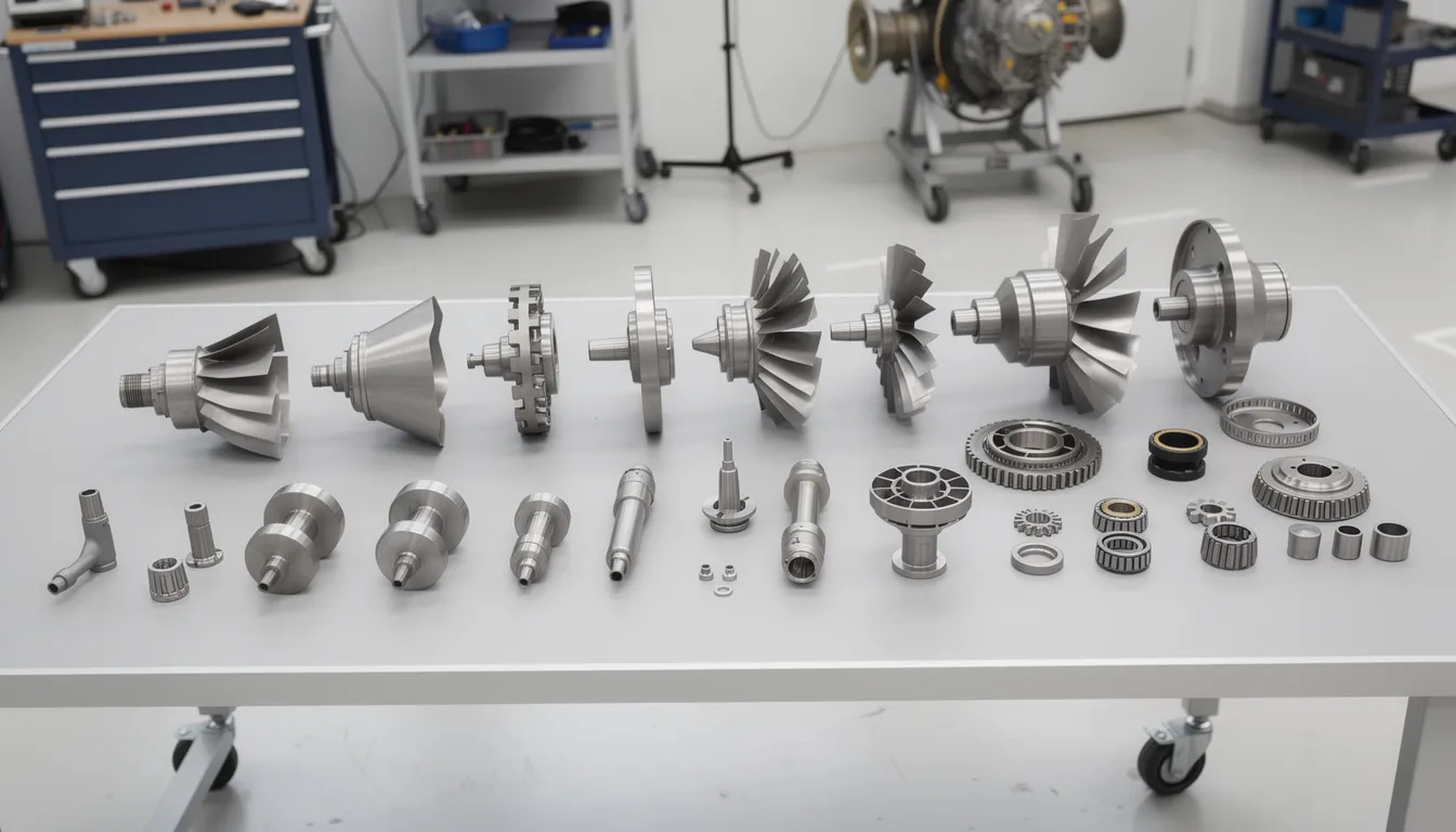
    An aerospace quality inspector is closely examining a turbine component for any material defects, ensuring compliance with stringent quality standards in the aerospace manufacturing industry. This quality inspection process enhances operational efficiency and helps in reducing scrap rates within the production line.

    Governance, AS9100, and the Cost of Nonconformance

    AS9100 and related aerospace quality standards are often viewed as compliance obligations. In practice, they are governance frameworks that shape how scrap and nonconformance are prevented, detected, and managed. Weak governance surfaces as quality cost; strong governance protects margin.

    Key governance elements include documented configuration control, formal change management, supplier approval and monitoring, and structured handling of concessions and deviations. Each element affects COPQ outcomes. Uncontrolled design changes generate nonconformance when production builds to obsolete requirements. Inconsistent application of customer specifications leads to parts that meet internal standards but fail customer inspection. Ad hoc dispositions create precedents that are difficult to sustain under audit scrutiny.

    Audit and regulatory exposure is a practical consequence of governance gaps. Incomplete traceability, missing inspection records, and inconsistent MRB decisions trigger findings from customer quality representatives, FAA Designated Engineering Representatives, or EASA auditors. These findings are not merely administrative inconveniences. They signal to customers that the organization’s quality management system may not be reliable, affecting future business and contract negotiations.

    Governance is a shared responsibility across operations, quality, engineering, and program management. Treating it as solely a quality function responsibility guarantees gaps. When engineering releases changes without assessing production impact, when operations deviates from approved methods to meet schedule, or when program management accepts elevated risk without documented justification, governance erodes. The costs surface later as scrap, rework, concessions, and audit findings.

    Tightening governance directly reduces chronic NCM. When change control is rigorous, configuration errors decline. When MRB criteria are consistent and well-documented, disposition cycles shorten. When supplier approval includes process capability requirements, incoming material quality improves. Governance investment is prevention investment.

    From Local Fixes to a Coherent Scrap Reduction Strategy

    Isolated lean projects or local quality campaigns are insufficient for sustainable aerospace scrap reduction. A coherent, cross-functional strategy is required to achieve lasting improvement.

    The strategic framework for aerospace scrap reduction aligns around four pillars:

    Pillar

    Focus

    Key Actions

    Process Capability

    Ensure processes can consistently meet specifications

    Capability studies, tooling investment, method optimization

    Governance

    Maintain configuration control and change discipline

    Drawing control, change management, supplier approval

    Containment Discipline

    Limit scope when nonconformance occurs

    Rapid identification, segregation, predefined response protocols

    Root Cause Rigor

    Prevent recurrence through systemic correction

    Data-driven RCA, controlled change implementation, effectiveness verification

    A consistent set of metrics enables tracking progress and identifying areas for focus:

    • Yield by process step and operation
    • Rework hours as a percentage of production hours
    • MRB cycle time (days from identification to disposition)
    • Concession volume by part family and customer
    • Internal failure cost versus external failure cost

    Strategic focus should target high-leverage areas: flight-critical assemblies, bottleneck special processes, and chronic nonconformance families. Not all scrap events are equal. A 5% reduction in scrap on a high-value, long-lead titanium forging generates more margin impact than a 20% reduction on low-value standard hardware.

    For multi-site organizations, standardizing definitions, codes, and escalation paths across plants is essential to understanding enterprise-level scrap impact. When each site uses different nonconformance codes or different criteria for classifying scrap versus rework, enterprise reporting becomes unreliable. Standardization enables meaningful comparison and the identification of best practices for transfer across sites.

    Implications for Aerospace MRO and In-Service Operations

    Scrap and nonconformance dynamics differ in MRO environments, where the asset is already in service and turnaround time is critical. The cost structures and time pressures create distinct challenges that require adapted approaches.

    The cost of scrapping a repairable unit in MRO extends beyond material value. Unplanned procurement of new hardware extends turnaround time. Extended TAT may trigger AOG events, with operators unable to return aircraft to service. Contract penalties with airlines or operators compound the direct cost. The ripple effects on customer satisfaction and future business can exceed the immediate financial loss.

    Repair development, repair station capability, and configuration control of service bulletins and Airworthiness Directives all affect MRO scrap rates. When repair methods are marginal, blending limits are tight, or inspection interpretations vary between shifts, scrap of otherwise serviceable components increases. Consider a CFM56 or LEAP engine shop facing repeated scrap of fan blades due to marginal blending limits and inconsistent inspection interpretations. Each scrapped blade represents both a direct loss and a potential TAT extension.

    The same strategic levers apply in MRO: process capability, governance, containment, and root cause rigor. However, timelines are compressed and customer pressures are immediate. Efficient operations depend on having repair methods qualified, inspection criteria clear, and disposition authority delegated to the appropriate level. Delays that might be tolerable in OEM production become unacceptable in MRO, where every day of TAT affects customer operations.

    The image depicts an aircraft engine being serviced in a maintenance, repair, and overhaul (MRO) facility, showcasing aerospace manufacturers' commitment to quality management and operational efficiency. Technicians are engaged in quality inspection and predictive maintenance to ensure the engine meets safety standards and reduces potential scrap during the production process.

    How Connect981 Fits: Unified View of Scrap, Nonconformance, and Operational Risk

    The strategic themes in this article require operational implementation. Organizations need visibility into where scrap originates, which processes drive chronic nonconformance, and how containment actions propagate across plants and suppliers.

    Connect981 provides a unified operations layer that brings work instructions, nonconformance records, quality inspection data, and supplier interactions into a single view. This unified visibility supports governance, traceability, and root cause analysis by eliminating the fragmentation that characterizes many aerospace operations today. When nonconformance data, process parameters, and supplier lot information exist in disconnected systems, the data-driven RCA required for reducing scrap becomes impractical.

    The platform’s focus on aerospace manufacturing and MRO enables consistent handling of serial numbers, configurations, concessions, and inspection history across plants and suppliers. Decision quality improves when leaders can see patterns across the organization rather than relying on site-by-site reporting with inconsistent definitions.

    Organizations that want to explore how their current scrap and COPQ picture could be made visible at an enterprise level can request a demo of Connect981.

    Conclusion: Treating Scrap as a Managed, Measured Risk

    Aerospace scrap reduction is about managing financial and program risk through disciplined processes and governance. Reducing scrap is not a housekeeping exercise or an environmental initiative. It is a margin protection strategy with direct consequences for program performance, customer relationships, and competitive position.

    The structural levers are clear: process capability that matches specification requirements, special process control that prevents unverifiable defects, strong NCM governance that accelerates disposition and protects traceability, containment discipline that limits the scope of quality events, and root cause rigor that prevents recurrence.

    Future articles in this series will address detailed COPQ modeling methods, advanced root cause analysis techniques for aerospace applications, special process qualification strategies, and AS9100-aligned governance structures. Each topic connects to the framework established here.

    For executives, the call to action is straightforward: treat scrap and nonconformance data as core performance indicators, reviewed at the same cadence as schedule adherence and EBITDA. The organizations that achieve operational excellence in aerospace are those that treat cost of poor quality as a strategic variable they intentionally design and govern, not as an unavoidable cost of doing business.

  • First-Pass Containment

    First-pass containment commonly refers to the immediate actions taken to isolate, identify, and control potentially nonconforming product, material, or process output as soon as an issue is detected. Its purpose is to prevent further use, shipment, or processing of affected items while the organization verifies scope and decides on next steps.

    In manufacturing and regulated operations, first-pass containment is an initial control step, not a final disposition. It may include stopping a line or operation, segregating stock, placing inventory on hold, tagging affected units, blocking transactions in MES or ERP, or increasing inspection on suspect lots. The exact actions vary by process and quality system.

    The term generally includes short-term actions performed before full root cause analysis is complete. It does not by itself mean the issue has been corrected, that corrective action is complete, or that all affected material has been fully identified.

    What it includes

    • Immediate control of suspect product or process output

    • Temporary measures to reduce further escape or use

    • Initial scoping of affected lots, serial numbers, work orders, or time windows

    • Communication to operations, quality, and sometimes suppliers or customers when relevant

    • System-level holds or status changes to preserve traceability and prevent movement

    What it does not include

    • Formal root cause determination

    • Permanent corrective action

    • Final material review or disposition

    • Verification that recurrence risk has been eliminated

    Operational meaning

    In daily workflows, first-pass containment often appears as the first documented response after a defect, test failure, process deviation, or supplier issue is found. Quality teams may open an NCR, place affected inventory in quarantine, trigger additional inspections, and use traceability records to identify where else the issue could exist. In digital environments, containment can also involve transaction locks, alerts, genealogy review, and status changes across MES, ERP, or QMS records.

    Common confusion

    First-pass containment is often confused with correction, corrective action, and disposition.

    • Correction is the action taken to fix a detected problem or affected item.

    • Corrective action addresses the underlying cause to reduce recurrence.

    • Disposition determines what happens to the affected material, such as rework, scrap, return, or use-as-is approval where applicable.

    Containment comes earlier and is mainly about immediate control.

  • calibration

    Core meaning

    Calibration commonly refers to the documented comparison of a measurement device or system against a known reference standard to determine and, when allowed, adjust its accuracy.

    In industrial and regulated manufacturing environments, calibration:

    – Uses traceable reference standards with known accuracy
    – Quantifies measurement error (bias, offset, drift)
    – Confirms that the device meets predefined tolerances
    – Records results, dates, and due dates for audit and quality control

    Calibration may include adjustment of the instrument to bring readings within acceptable limits, but the comparison and documentation step is always required.

    Use in manufacturing operations

    In manufacturing systems, calibration is applied to:

    – **Process instruments**: pressure, temperature, flow, level transmitters, controllers
    – **Quality and test equipment**: gauges, micrometers, CMMs, load cells, torque tools, vision systems
    – **Environmental monitoring**: humidity, differential pressure, particle counters, cleanroom sensors

    Typical operational uses include:

    – Establishing calibration intervals and due dates in a calibration management or CMMS system
    – Locking out or flagging production equipment in MES/SCADA when a critical sensor is overdue for calibration
    – Using calibration data to determine if product measured since the last in-tolerance verification is potentially affected
    – Providing objective evidence for audits that measurement systems used to release product are controlled and within specification

    Boundaries and exclusions

    Calibration in this context:

    – **Includes**: comparison to a standard, determination of error, acceptance decision, documentation, and sometimes adjustment
    – **Excludes**: general equipment maintenance (e.g., cleaning, lubrication) that does not involve measurement accuracy, and informal “checks” without reference standards or records

    It is related to, but distinct from:

    – **Verification**: confirming a device meets requirements without necessarily adjusting it
    – **Validation**: confirming that a process or system is fit for intended use; calibration may be an input but is not the same activity

    Common confusion and correct usage

    Common areas of confusion include:

    – **Calibration vs. zeroing/offset**: Zeroing a scale or taring a balance is not full calibration unless it is performed against a known standard and documented.
    – **Calibration vs. adjustment**: Adjustment changes the device reading; calibration is the act of determining and documenting how the device reads relative to a standard. Some procedures combine both but they are conceptually separate steps.
    – **“Self-calibrating” devices**: Many instruments can auto-adjust internally, but in regulated and quality-critical environments they are still subject to periodic external calibration against traceable standards.

    Site context: calibration and MES, quality, and scrap

    Within MES and integrated quality systems, calibration data is often used to:

    – Generate alerts when critical instruments approach or reach calibration due dates
    – Trigger holds or extra review when calibration results show significant drift
    – Link measurement devices and their calibration status to specific work orders, batches, or serial numbers

    For high-risk products (such as aerospace components), systems may:

    – Issue targeted alerts when measurement drift trends toward limits
    – Block completion of inspections if the associated gauge or sensor is out of calibration
    – Support traceability between nonconformances and the calibration status of the equipment used

    In this context, calibration is a key element of measurement system control that underpins reliable specifications, scrap prevention, and audit-ready records.

  • First Article Inspection (FAI) in Aerospace Manufacturing

    First Article Inspection (FAI) in Aerospace Manufacturing

    First Article Inspection is the formal verification step that confirms a manufacturing process can consistently produce parts meeting all engineering requirements. In aerospace, this process determines whether a supplier’s production methods, tooling, and materials will deliver conforming hardware before committing to full-rate production or after a major change to design, process, or facility.

    The First Article Inspection Report, commonly called the FAIR, serves as the documented evidence of this validation. It captures material certifications, dimensional measurements, special process approvals, and functional test results in a structured format aligned with AS9100-compliant quality management systems. For aerospace organizations, the FAIR is both a quality gate and a long-term traceability record.

    This pillar guide from Connect981 covers the complete FAI landscape: when first article inspection is required, how to execute the FAI process, what documentation AS9102 demands, how to maintain traceability across the supply chain, and how digital tools reduce FAI cycle time without sacrificing compliance.

    What is First Article Inspection (FAI)?

    First article inspection in aerospace is a formal, documented verification that the manufacturing process, tooling, methods, and suppliers can produce a part that conforms to all engineering, material, and functional requirements. The inspection evaluates a production-representative sample manufactured under normal production conditions, not a hand-finished prototype or engineering sample.

    The critical distinction is that FAI evaluates the manufacturing system, not just a single part. The goal is to prove process capability and consistency before mass production begins. A successful FAI establishes the production baseline and becomes the reference for any future partial FAI or delta FAI activities.

    Aerospace FAI is governed by SAE AS9102, with the latest revision (AS9102D) released in March 2024. This standard defines the documentation structure, required content, and acceptance criteria that suppliers must follow.

    Key terms used throughout this guide:

    • First article inspection: The verification event that validates a manufacturing system’s capability
    • FAIR: The documented report package containing Forms 1, 2, and 3 plus supporting evidence
    • AS9102: The SAE standard governing FAI documentation requirements
    • Ballooned drawing: Engineering drawing with numbered identifiers linking each characteristic to inspection data
    • Characteristic accountability: The systematic verification and recording of all design features
    • Key characteristics: Features with highest risk to product performance or safety requiring special controls

    Unlike routine in-process or final inspection, FAI is event-driven. It occurs at specific triggers such as new part introduction, major design changes, or supplier transitions. The inspection scope is exhaustive, covering 100% of drawing characteristics rather than statistical sampling.

    Regulatory and Standards Context for FAI

    First article inspection matters to aerospace regulators, primes, and certification bodies because it provides documented evidence that production processes meet design intent before hardware enters service. The FAI requirement flows from quality standards through purchase orders into contractual obligations.

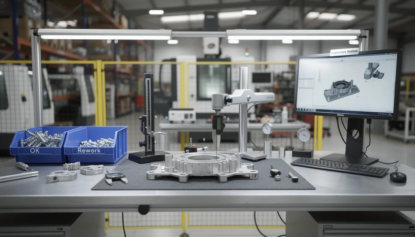
    The image depicts an aerospace manufacturing facility equipped with quality inspection equipment and documentation stations, highlighting the critical aspects of the first article inspection process. Various tools and documentation are present to ensure compliance with stringent quality control and assurance standards in the aerospace industry.

    The regulatory framework includes:

    • AS9100 series: The primary aerospace quality management system standard, with AS9102 referenced in Clause 8.5.1.3 for production process verification
    • EN9100 and JISQ9100: European and Japanese equivalents that align with AS9102 principles
    • SAE AS9102: The specific standard for FAI documentation, developed by the International Aerospace Quality Group (IAQG)

    OEMs like Boeing, Airbus, Lockheed Martin, and Rolls-Royce flow down FAI requirements through purchase orders and quality clauses. These clauses typically reference AS9102 explicitly and may add customer-specific requirements for FAIR format, approval workflows, or delegated representative involvement.

    FAI connects to multiple regulatory environments:

    • FAA and EASA production approvals under 14 CFR Part 21 and European equivalents
    • US Department of Defense contracts subject to DFARS clauses requiring documented first-article verification
    • Export-controlled work under ITAR or EAR regulations

    For organizations pursuing AS9100 certification, FAI records serve as evidence of process control and design understanding during audits. Auditors specifically verify linkage between the first build and ongoing production control plans.

    In aerospace, FAI (AS9102) often integrates with Advanced Product Quality Planning per AS9145. The FAI serves as the production validation step in APQP Phase 4, demonstrating that the production process can meet design specifications and quality requirements.

    When is First Article Inspection Required?

    Timing and triggers for FAI are defined by AS9102 and customer contracts. Understanding these triggers is essential for compliance and for avoiding rework when a FAIR is rejected for scope issues.

    Typical triggers for a full FAI per AS9102 and common OEM practices:

    Trigger

    Description

    New part number

    First production of a new design or purchase from a new supplier

    New supplier

    First production by a supplier, regardless of prior part history

    New facility

    First production at a new manufacturing location

    New methods/tooling

    Adoption of manufacturing methods or tooling differing from approved baseline

    Material changes

    New raw material forms or supplier sources

    Engineering design changes often require FAI. The extent depends on what changed:

    • Full FAI: Required when changes affect multiple characteristics or fundamental process assumptions
    • Partial FAI: Appropriate when only a subset of characteristics changed (e.g., two bore diameters at Rev C)
    • Delta FAI: Used when production transfers between facilities or when tooling relocates with unchanged manufacturing sequence

    Process change triggers include major changes in NC programs, process routing, manufacturing sequence, special processes (heat treat, plating, welding), or raw material specifications.

    Many OEM supplier quality manuals mandate FAI after a production lapse of 24 months or more. This reflects concern that knowledge degradation, personnel turnover, and equipment drift during extended gaps may introduce undetected changes to process capability.

    A separate cluster article on when FAI is required expands on these triggers with specific AS9102D clause references and OEM examples.

    FAI vs PPAP and Other Approval Processes

    Readers often confuse first article inspection FAI with the Production Part Approval Process. Both serve as quality gates, but they differ in scope and origin.

    PPAP originated in the automotive industry as part of the APQP framework. It covers a broad range of deliverables: process capability studies, measurement system analysis, control plans, and long-term production readiness documentation.

    FAI (AS9102) focuses heavily on characteristic verification and traceability for a single build event. It validates that a manufacturing process can produce conforming parts but does not inherently require statistical capability studies or control plan submissions.

    Key distinctions:

    Aspect

    FAI (AS9102)

    PPAP

    Primary focus

    Characteristic verification, material/process traceability

    Broad production readiness

    Documentation

    Three AS9102 forms plus attachments

    Up to 18 elements including capability studies

    Industry origin

    Aerospace (IAQG)

    Automotive (AIAG)

    Scope

    Single build event validation

    Long-term production capability

    FAI can be considered a subset of a full PPAP package. However, aerospace primes may require both AS9102 FAIR and additional PPAP or AS9145 deliverables for complex programs.

    Common aerospace customer requirements include:

    1. AS9102 FAIR only: Standard for many detail parts and lower-tier suppliers
    2. AS9102 plus capability studies: Required for key characteristics on critical assemblies
    3. Full APQP/PPAP evidence: Mandated for new product development programs with extensive design responsibility

    The cluster article FAI vs PPAP compares required documents line-by-line across both approval process frameworks.

    FAI Documentation and AS9102 Forms

    The FAIR is the core deliverable of first article inspection. Unless a customer-specific template is mandated in the purchase order or supplier quality manual, the three AS9102 forms serve as the documentation standard.

    The three forms work together to establish complete traceability:

    Form

    Name

    Purpose

    Form 1

    Part Number Accountability

    Identifies the part, revision, FAI type, and reason

    Form 2

    Product Accountability

    Documents materials, special processes, and tests

    Form 3

    Characteristic Accountability

    Records inspection results for every balloon

    A ballooned drawing or 3D digital product definition identifies every characteristic with unique balloon IDs. These IDs map directly to line items on AS9102 Form 3, creating traceability between visual part definition and inspection results.

    Common supporting documents attached to a FAIR package:

    • Raw material certificates of conformance and mill test reports
    • Special process certifications (NADCAP approvals for heat treat, NDT, welding)
    • Functional test reports (pressure tests, electrical continuity)
    • Process flow diagrams or routing sheets
    • Setup sheets and work instructions
    • Nonconformance reports and corrective actions if applicable
    • Customer-approved concessions or deviations

    Key characteristics and critical-to-quality features must be explicitly identified using designators like “KC,” “CC,” or customer-specific markings. These designations signal which features warrant special controls during production.

    Connect981 can host digital FAIR templates aligned with AS9102D, auto-populate fields from ERP and MES data, capture ballooned drawing links, and enforce mandatory attachments before FAIR submission.

    A dedicated cluster article on FAI documentation requirements walks through each field in AS9102 Forms 1–3 with completed examples.

    AS9102 Form 1 – Part Number Accountability

    Form 1 establishes the identity and context for the FAI. Required content includes:

    • Part number and nomenclature
    • Drawing or model number with revision level
    • FAI type (full, partial, delta)
    • Reason for FAI (new part, design change, facility transfer, production lapse)
    • Date of FAI and effective date of any triggering change

    Form 1 distinguishes between Detail FAI (single-component parts manufactured as a discrete unit) and Assembly FAI (multi-component assemblies with a bill of materials).

    For assemblies, Form 1 must list:

    • Each lower-level part number
    • FAIR reference if an FAI exists for that component
    • Serial or lot numbers to maintain traceability across levels

    This hierarchical approach ensures that if a sub component fails FAI or has a nonconformance, the impact on overall assembly acceptance is transparent and traceable.

    AS9102 Form 2 – Product Accountability (Materials and Processes)

    Form 2 documents raw materials and special processes used to manufacture the first article.

    Raw material entries include:

    • Material designation (e.g., 7075-T6 aluminum plate, Ti-6Al-4V bar stock)
    • Material specification reference (e.g., AMS-QQ-A-250/12 for aluminum)
    • Heat lot or batch numbers for traceability
    • Certificate of conformance reference

    Special process entries include:

    Process Type

    Example Specification

    Required Documentation

    Anodizing

    AMS2469, Type II or III

    Process spec, supplier code, approval status

    Passivation

    AMS2700

    NADCAP certification, lot number

    Heat treatment

    AMS specification with temp/time

    Furnace certification, chart records

    NDT

    Customer or NADCAP spec

    Operator certification, inspection report

    Welding

    AMS or customer spec

    Filler material, heat input, post-weld treatment

    Functional tests such as pressure tests, torque tests, or electrical continuity for harnesses are linked via procedure numbers and test report identifiers.

    Example row for a machined strut fitting:

    Material

    Spec

    Heat Lot

    CoC Reference

    7075-T651 Aluminum Plate

    AMS-QQ-A-250/12

    H-2024-0847

    CoC-2024-0847-A

    AS9102 Form 3 – Characteristic Accountability

    Form 3 is typically the most time-consuming element of FAIR preparation. Each line corresponds to a characteristic from the ballooned drawing.

    Required fields for each characteristic:

    Field

    Description

    Balloon number

    Links to ballooned drawing

    Drawing sheet and zone

    Location reference for multi-sheet drawings

    Characteristic description

    “Bore OD,” “Thread M10x1.5,” “Flatness of seating surface”

    Specification or tolerance

    Nominal dimension with tolerance band

    Key characteristic designator

    KC, CC, or standard feature

    Inspection method

    CMM, micrometer, visual, functional test

    Measured result

    Actual numerical value or attribute result

    Gage ID

    Traceable to calibration records

    Acceptance status

    Accept, reject, or conditional

    Characteristics are recorded as either attribute data (pass/fail for thread presence) or variable data (numerical measurement for bore diameter). Using the correct data type ensures accuracy and supports process control.

    Inspection methods may include CMM, hand tools (micrometers, calipers), optical comparators, calibrated tools, or automated scanning equipment. Gage ID and calibration state must be traceable to ISO 17025 labs where applicable.

    Manual Form 3 population using spreadsheets is error-prone. Connect981 can ingest CMM output files and auto-fill inspection results linked to balloon IDs, reducing transcription errors and preparation time.

    Raw Material and Dimensional Records in FAI

    Material and dimensional integrity together determine whether the first article is acceptable and reliable in service. Both require rigorous documentation.

    A quality inspector is using a coordinate measuring machine to perform a first article inspection on an aerospace component, ensuring that it meets the specified design requirements and quality standards. This inspection process is crucial for maintaining product reliability and customer confidence in the aerospace industry.

    Raw material record requirements:

    • Mill test reports documenting chemical composition and mechanical properties
    • Certificates of conformance from material suppliers
    • Traceability to heat lot numbers and purchase orders
    • For critical materials (titanium forgings, composite prepreg), complete mechanical test data

    Aerospace-specific scenarios demand heightened traceability. Titanium forgings for engine mounts require heat lot documentation linking specific material to the first article serial number. Composite prepreg materials have shelf-life limitations requiring lot tracking to ensure out-of-life material is not incorporated.

    Dimensional record requirements:

    • 100% of dimensions on the drawing for FAI
    • GD&T features including flatness, position, runout, and perpendicularity
    • Surface finish measurements where specified
    • Thread verification using appropriate gages

    Common measurement tools in aerospace FAI:

    Tool Type

    Application

    CMM

    Complex geometry, GD&T features, high-precision dimensions

    Portable arms

    Large parts, field measurements

    Laser scanners

    Complex surfaces, rapid data capture

    Pin gages

    Go/no-go verification of holes

    Thread gages

    Pitch and major diameter verification

    Hardness testers

    Material property verification per spec

    Dimensional records must include gage IDs and calibration due dates. Inadequate metrology control is a frequent audit finding. A gage out of calibration at time of measurement can invalidate FAI results for that characteristic.

    The cluster article on FAI traceability explores how raw material, process, and dimensional records tie into serialized part histories over an aircraft’s service life.

    Operational Execution: The FAI Workflow in Aerospace

    The FAI workflow spans multiple functions and requires coordination between quality, manufacturing engineering, supply chain, and the customer. Understanding the operational sequence reduces cycle time and prevents rework.

    Planning phase activities:

    • Review contract and purchase order quality clauses to confirm FAI scope
    • Identify OEM-specific FAIR format or submission portal requirements
    • Hold pre-FAI meeting with quality, manufacturing engineering, and supply chain
    • Confirm latest drawing revision and specifications are available

    Manufacturing engineering planning:

    • Develop process routing and machine/tool selection
    • Identify key characteristics and inspection methods
    • Create digital work instructions or travelers specific to FAI build
    • Verify special process approvals are current (NADCAP certifications)

    The first article must be manufactured under normal production conditions using approved programs, fixtures, materials, and qualified personnel. FAI performed on engineering samples or under special lab conditions does not validate the actual production process.

    Inspection and documentation execution:

    • Balloon the drawing with unique characteristic identifiers
    • Execute dimensional, material, and functional tests per inspection plan
    • Capture results with full traceability: gage IDs, calibration status, inspector identification
    • Document any nonconformances and link to corrective actions

    Review and approval sequence:

    • Internal quality review for accuracy and completeness
    • Customer or delegated representative submission
    • Response to clarification requests within required timeline
    • Final sign-off before rate production release

    Connect981 orchestrates this workflow end-to-end, from digital traveler creation and step-by-step work instructions to automated FAIR compilation and customer portal submission.

    Typical Step-by-Step FAI Process

    This sequential checklist reflects what quality and manufacturing engineers execute during a complete FAI:

    1. Confirm FAI requirement and scope: Review PO quality clauses and determine full, partial, or delta FAI type
    2. Gather latest design data: Obtain current drawing revision, 3D model, specifications, and engineering change notices
    3. Balloon the drawing/model: Assign unique identifiers to every characteristic per customer conventions
    4. Define inspection methods and sampling: Specify gages, CMM programs, and measurement approach for each characteristic
    5. Schedule and build the first article: Execute manufacturing plan using standard production processes and qualified personnel
    6. Perform inspections and tests: Measure all characteristics, conduct functional tests, verify material properties
    7. Compile AS9102 Forms 1–3: Populate all fields with full traceability to gages, materials, and processes
    8. Attach supporting documents: Include CoCs, process certifications, test reports, and any nonconformance records
    9. Internal review and sign-off: Independent verification by quality engineer or supervisor
    10. Customer submission and response: Transmit FAIR via agreed method and respond to questions within timeline
    11. Archive FAIR and link to work orders: Store approved FAIR with connection to serial numbers and purchase orders

    Coordination touchpoints occur at planning (scope agreement), mid-build (observation of critical steps), and review (internal verification before customer submission). Any nonconformances discovered during FAI must be documented with corrective actions, even if the FAIR is approved with concessions.

    Delta FAI and Partial FAI in Practice

    Delta and partial FAIs avoid redoing a full first article inspection when only limited changes have occurred. Both maintain compliance while reducing redundant work.

    Partial FAI focuses only on characteristics affected by a change. For example, if drawing Rev B changes only two bore diameters and a tapped hole position, the partial FAI measures only those three features while referencing the prior full FAIR for unchanged characteristics.

    Delta FAI is a customer- or OEM-defined variation used when:

    • Production transfers between facilities (Wichita to Montreal)
    • Tooling relocates to new equipment
    • Previously approved processes are updated within defined tolerances

    Documentation expectations for both types:

    Requirement

    Partial FAI

    Delta FAI

    FAIR type statement

    “Partial” clearly stated

    “Delta” per OEM definition

    Original FAIR reference

    Required

    Required

    Scope definition

    Changed characteristics only

    Facility/equipment changes

    Supporting evidence

    Process documentation for changes

    Equipment qualification records

    Concrete example: Moving a machining operation from Plant A to Plant B in 2027 would trigger a delta FAI capturing facility-related changes while referencing the original FAIR from the initial production baseline.

    Connect981 versions FAIRs, tracks lineage between full and partial/delta FAIs, and presents a clear audit trail for regulators and customers.

    Common FAI Workflow Challenges and Errors

    FAI failures often stem from preventable documentation and process errors rather than fundamental manufacturing problems. Understanding these risks helps organizations avoid costly errors and customer rejections.

    Documentation issues:

    • Using outdated drawings or engineering documentation (revision mismatch)
    • Inconsistent characteristic numbering between ballooned drawings and Form 3
    • Missing revision updates or engineering change notices
    • Incomplete attachment of required certificates and test reports

    Metrology and data errors:

    • Mis-typed numeric results when transcribing from CMM reports to FAIR forms
    • Incomplete gage ID fields or missing calibration evidence
    • Misuse of attribute versus variable data for critical dimensions
    • Measurement results recorded without units or tolerance context

    Process-related problems:

    • Performing FAI on engineering samples that do not represent actual production process
    • Skipping required special process approvals before FAI build
    • Manufacturing under non-standard conditions (different fixtures, unqualified personnel)

    Communication gaps:

    • Unclear FAI scope communicated between OEM and supplier
    • Customer-specific FAIR formats not shared early in program
    • Late change notices during FAI builds causing scope confusion
    • Delayed responses to customer clarification requests

    The cluster article on common FAI errors presents a detailed checklist of avoidable mistakes and detection methods before customer submission.

    Platforms like Connect981 reduce these errors through enforced templates, automated data import from CMM systems, validation checks before submission, and a single source of truth for drawing revisions.

    Traceability and Record Retention for FAI

    Traceability is central to aerospace safety cases and explains why FAI is so documentation-intensive. The FAIR creates an unbroken chain connecting manufactured parts to their materials, processes, and verification records.

    FAI records connect:

    • Part serial numbers or lot numbers
    • Material lots with heat numbers and mechanical properties
    • Special process lots with vendor identification and approval status
    • Inspection results with gage IDs and inspector identification
    • Responsible parties at each manufacturing and verification step

    This chain enables rapid investigation when field issues occur. If a component fails in service, investigators can trace backward from the serial number to the FAI, then to the specific material heat lot, special process vendor, and dimensional verification records.

    Typical retention expectations:

    Context

    Retention Period

    Commercial aerospace

    10+ years, often through aircraft service life (20-40 years)

    Defense contracts

    Program life or indefinite per contract requirements

    Safety-critical components

    Through product lifecycle plus investigation window

    Rapid retrieval capability matters for regulatory audits, customer investigations, and accident analysis. Older revisions and superseded FAIRs must remain accessible even after design updates.

    The risk of scattered PDFs and spreadsheets across network drives creates compliance exposure. Multi-site operations often struggle with FAIR location and version control, particularly after personnel turnover or facility acquisitions.

    Connect981 centralizes FAIR data, links it to work orders and serial numbers, and provides controlled access to OEMs and tiered suppliers via a shared digital layer.

    The cluster article on FAI traceability deep-dives into serial number management, lot tracking, and integration with ERP, MES, and QMS systems.

    Digital Systems and Automation for FAI

    The aerospace industry is transitioning from paper-based FAIs and standalone spreadsheets toward integrated digital workflows. This shift addresses longstanding pain points while maintaining stringent requirements.

    A digital tablet is positioned on an aerospace manufacturing floor, displaying detailed work instructions related to the first article inspection process. This setup emphasizes the importance of quality control and adherence to specified requirements in the aerospace industry’s production process.

    Common manual pain points:

    • Repeated data entry across inspection logs, spreadsheets, and FAIR forms
    • Inconsistent templates across programs and suppliers
    • Difficulty aggregating CMM output files from different equipment brands
    • Long FAIR cycle times (multiple days per part)
    • High rework rates due to formatting or transcription errors

    Digital FAI capabilities:

    • Automated drawing ballooning and characteristic extraction from CAD/DPD
    • Direct import of CMM and scanner data into Form 3 fields
    • Auto-population of material and process information from MES/ERP
    • Validation checks before submission (missing fields, calibration status)
    • Version control with audit trails

    Integration with MES, ERP, and QMS provides shared part master data, process routings, nonconformance linkage, and document control. This reduces duplication and ensures accuracy between systems.

    Connect981 serves as a unified operations platform that:

    • Provides digital work instructions including FAI-specific steps
    • Captures inspection data at the point of use via mobile devices
    • Links FAIRs to work orders, purchase orders, and supplier records
    • Offers a shared portal for OEM-supplier FAI collaboration with permissioned access

    In aerospace MRO environments, digital FAI systems verify first article repairs or modifications, document new repair procedures, and integrate with maintenance records for product reliability traceability.

    The cluster article on digital travelers and FAI focuses on how digital work instructions and FAIRs work together on a connected shopfloor.

    AI and Analytics in FAI

    Emerging AI and analytics capabilities augment FAI workflows while keeping domain experts in control.

    AI-assisted characteristic extraction from CAD models and engineering drawings reduces manual ballooning time. Machine learning models trained on aerospace drawings can identify features, extract dimensions and tolerances, and propose balloon numbering schemes aligned with customer conventions.

    Advanced analytics on FAIR data across programs and suppliers identifies systemic issues:

    • Recurring nonconformances on specific key characteristics
    • Machines or tooling prone to problems (suggesting calibration drift or wear)
    • Material suppliers with higher nonconformance rates

    Connect981 uses AI-assisted root cause analysis to highlight high-risk features before they fail in FAI or production. Predictive insights flag characteristics similar to historical problem areas for additional review.

    AI augments but does not replace domain experts. Quality engineers, metrologists, and manufacturing engineers retain judgment over design changes, process controls, and supplier qualification decisions.

    Reducing FAI Cycle Time Without Sacrificing Compliance

    FAIs often sit on the critical path for program launches and design changes. A program awaiting FAI approval cannot begin full production run, which delays revenue and may incur customer penalties.

    Typical drivers of long FAI cycle times:

    • Late or unclear requirements from OEMs
    • Fragmented systems (drawings, specs, FAI forms in different locations)
    • Manual data entry and transcription at multiple steps
    • Uncoordinated metrology scheduling
    • Back-and-forth clarifications with customers

    Best practices for acceleration:

    Practice

    Impact

    Early planning and scope confirmation

    Prevents rework from unclear requirements

    Pre-approved templates and conventions

    Reduces formatting questions

    Concurrent inspection planning

    Eliminates metrology scheduling delays

    Digital data capture at point of use

    Eliminates transcription errors

    Integrated FAIR generation

    Cuts preparation time by 75%+

    Digital tools cut FAI turnaround through automated data capture, single-click FAIR generation, integrated approvals, and shared visibility for OEMs and suppliers. Organizations report reducing FAI preparation from 16 hours to 4 hours per part using automated approaches.

    The cluster article on reducing FAI cycle time offers quantitative examples and case scenarios demonstrating specific acceleration strategies.

    FAI in Defense and High-Regulation Contracts

    Defense, space, and safety-critical systems often add requirements beyond standard AS9102 FAI. Understanding these additions prevents compliance gaps on regulated programs.

    Defense-specific FAI requirements:

    • Contract-unique FAI forms replacing or supplementing AS9102 formats
    • Additional review gates with government quality representative involvement
    • DCMA (Defense Contract Management Agency) witness requirements for certain operations
    • Direct linkage between FAI acceptance and payment milestones

    Some defense contracts tie FAI approval to program risk reviews. If the FAI reveals unexpected manufacturing challenges, program risk posture escalates, triggering additional oversight.

    ITAR and export control implications:

    FAI data including drawings, 3D models, and FAIRs may be controlled technical data under ITAR or EAR. This means:

    • FAIRs cannot be freely shared with non-U.S. suppliers
    • Foreign nationals may require export licenses for access
    • Digital systems must incorporate access controls and data segregation
    • Audit trails must document who accessed controlled data

    Connect981’s shared yet permissioned environment supports collaborative FAIs on defense programs while respecting data segregation. Access controls, encryption, and user authentication prevent unauthorized access to controlled FAI data.

    The cluster article on FAI in defense contracts addresses these topics with detailed examples including common clauses and flow-down language.

    The Future of Automated and Connected FAI

    First article inspection will evolve significantly over the next 5–10 years as model-based definition and automated metrology become standard across the aerospace industry.

    The image depicts a modern automated manufacturing cell featuring advanced robotic inspection equipment, designed for the inspection process in the aerospace industry. This setup is crucial for ensuring product reliability and adherence to stringent quality control requirements during the first article inspection process.

    Model-Based Definition (MBD) and Digital Product Definition:

    MBD embeds all design intent, tolerances, and annotations in 3D CAD models. This enables:

    • Direct-to-CAD FAI without reliance on 2D drawings
    • Automatic characteristic extraction for ballooning
    • CMM software reading tolerance data directly from models
    • Reduced manual interpretation and ensure accuracy

    Automated metrology trends:

    • Robotic CMM cells performing hands-off measurement
    • Inline 3D scanners feeding directly into FAIR generation
    • Vision-based inspection capturing attribute data automatically
    • High-volume 100% inspection replacing statistical sampling

    Digital thread integration:

    FAI data will increasingly connect to PLM, ERP, MES, QMS, and fleet maintenance systems. This enables:

    • Closed-loop quality: FAI observations feed directly into control plans
    • Lifecycle traceability: FAI linked to serial numbers and maintenance records
    • Continuous improvement: Aggregate FAI analytics identify systemic issues
    • Predictive intelligence: ML models flag high-risk designs before FAI

    Platforms like Connect981 serve as the connective layer between these systems, enabling standardized FAI workflows across global factories and multi-tier supplier networks. Industry standardization of digital FAIR data exchange will reduce proprietary silos and enable easier OEM-supplier collaboration.

    The future state is a scenario where suppliers receive design specifications, automatically generate FAI plans, manufacture with digital work instructions, compile FAIRs from CMM data and material certifications, submit via digital portal, and receive approval within days rather than weeks.

    Organizations that standardize FAI workflows reduce cycle time, cut costly errors, and maintain customer confidence through audit-ready documentation. The path forward requires evaluating current FAI maturity, identifying manual bottlenecks, and adopting digital tools that integrate with existing systems.

    Connect981 enables aerospace manufacturers and suppliers to modernize their FAI process without replacing ERP or MES infrastructure. Request a demo to see how digital FAI workflows can work for your next project.

  • Sensitivity analysis

    Sensitivity analysis is a method for evaluating how much an output changes when one or more inputs, assumptions, or parameters are varied. It is commonly used in manufacturing, quality, planning, and analytics to understand which factors have the greatest influence on a result.

    In practice, the term usually refers to testing a model, calculation, forecast, or process metric by changing selected variables and observing the effect. Examples include changing demand assumptions in a planning model, adjusting process parameters in a yield model, or examining how scrap rate, cycle time, or supplier lead time affects cost or schedule performance.

    Sensitivity analysis does not by itself prove cause and effect, validate a model, or determine the single correct operating setting. It is an analytical technique for understanding responsiveness, uncertainty, and relative influence.

    Where it applies

    In industrial and regulated operations, sensitivity analysis may appear in:

    • production planning and capacity scenarios

    • cost, margin, and inventory modeling

    • quality and process-improvement studies

    • risk assessments and contingency planning

    • engineering and process development work, including design of experiments and simulation

    It can be performed with simple spreadsheet models or with more formal simulation, statistical, or optimization tools.

    Common confusion

    Sensitivity analysis is often confused with scenario analysis and design of experiments.

    • Scenario analysis usually compares a defined set of combined conditions, such as best case, expected case, and worst case.

    • Sensitivity analysis focuses on how the output responds when specific inputs are changed, often one at a time or across a defined range.

    • Design of experiments (DoE) is a structured experimental method used to study factor effects and interactions in real or simulated processes.

    It is also not the same as measurement sensitivity, which refers to how responsive an instrument or detection method is.

    Manufacturing example

    A planner may test how a 5 percent change in forecast demand, supplier lead time, or machine uptime affects required inventory and promised ship dates. A quality engineer may assess how variation in temperature, dwell time, or torque changes predicted defect rates. In both cases, the goal is to identify which inputs matter most and where tighter control or better data may be needed.