Tag: Aerospace manufacturing

  • Digital FAIR Forms and Ballooned Drawings: Automating AS9102 FAI

    Digital FAIR Forms and Ballooned Drawings: Automating AS9102 FAI

    Digital FAIR Forms and Ballooned Drawings: Automating AS9102 FAI

    For most aerospace manufacturers, the slowest and most error-prone part of AS9102 first article inspection (FAI) is not the measurements themselves. It is turning complex drawings into ballooned characteristics and then mapping every requirement into Forms 1, 2, and 3. Digital FAIR forms and automated ballooned drawings target this exact bottleneck, replacing hand-marked prints and Excel templates with a structured, reviewable, and reusable data model.

    This article explains how modern tools automate ballooned drawings, populate AS9102 forms, and maintain one-to-one traceability between every drawing requirement and every Form 3 line. It also shows how digital FAIRs support partial and delta FAI, integrate measurement data, and create a foundation for long-term traceability.

    For teams putting this topic into daily operation, Connect 981’s aerospace execution solutions, real aerospace execution examples, digital AS9102 FAI help connect the concept to traceability, work-order reality, and audit-ready evidence.

    For teams putting this topic into daily operation, digital AS9102 FAI, a connected execution platform help connect the concept to traceability, work-order reality, and audit-ready evidence.

    The same operating model also depends on Connect 981’s aerospace operations guidance, practical aerospace operations FAQs, especially when decisions have to move across quality, production, suppliers, and program leadership without losing context.

    If you need a broader overview of how these capabilities fit into a full platform, see our AS9102 software overview.

    Why Ballooned Drawings and FAIR Forms Are Central to AS9102

    AS9102 revolves around a simple idea: every requirement in the design must be clearly identified, measured, and documented. Ballooned drawings and FAIR forms are how that happens in practice.

    The role of ballooned drawings in capturing every requirement

    A ballooned drawing is a drawing where every verifiable requirement is given a unique identifier (a “balloon” number). This typically includes:

    • Dimensions and tolerances (linear, angular, diameters, radii, etc.)
    • GD&T callouts (position, flatness, perpendicularity, profile, and others)
    • Surface finish requirements
    • Drawing notes that imply verification (e.g., “NO SHARP EDGES”, “DEBURR ALL EDGES”)
    • Material specifications and heat-treat conditions
    • Coatings and other special processes that must be verified

    Each balloon creates a discrete, traceable “characteristic” that should appear on Form 3. When ballooning is incomplete or inconsistent, characteristic accountability breaks down and AS9102 expectations are not met.

    How Forms 1, 2, and 3 relate to the drawing

    AS9102 Rev C structures the FAIR into three core forms:

    • Form 1 – Part Number Accountability: Identifies the part, configuration, and whether the FAIR is full, partial, or delta.
    • Form 2 – Product Accountability: Lists materials, special processes, and functional tests with traceable documentation.
    • Form 3 – Characteristic Accountability: Maps every ballooned characteristic to measured or verified results and compatibility evaluations.

    The ballooned drawing drives Form 3. Each balloon ID should correspond to exactly one Form 3 line, which then references the same part and revision context defined in Form 1 and the associated materials and processes summarized in Form 2.

    Common failure modes in manual FAIR creation

    Manual FAI processes typically involve printing drawings, marking balloons with a pen, and populating Excel-based forms. This approach is familiar but fragile. Common problems include:

    • Missed or duplicated balloons: Critical dimensions can be skipped entirely or numbered twice, resulting in gaps or conflicts in Form 3.
    • Mismatch between drawing and forms: Balloon numbering on paper does not match line numbering in Excel, making reviews and audits difficult.
    • Incorrect tolerance or unit interpretation: Values are re-typed manually, increasing the chance of misreading, rounding, or unit mix-ups.
    • Weak revision control: FAIRs are completed against one drawing revision while a newer revision is already in effect, but there is no systematic link.
    • Heavy reliance on tribal knowledge: Only a few experts know how to balloon in the “right way” or which Excel template applies to which customer.

    Digital FAIR tools focus on eliminating these failure modes by treating ballooning and forms as connected, governed data rather than as disconnected documents.

    How Digital Tools Automate Ballooned Drawings

    Digital ballooning is the starting point for any modern AS9102 workflow. Instead of manually adding balloons on paper, engineers work with digital drawings and software that recognizes and structures characteristics.

    Importing PDF and CAD-derived drawings

    Most FAI scenarios still rely on 2D drawings, even when the design originates from a 3D CAD model. Effective digital ballooning starts with robust import:

    • PDF drawing import: The system ingests released PDF drawings directly from PLM or document control, preserving scaling and clarity.
    • CAD-derived drawings: For organizations using model-based workflows, tools may import 2D drawings generated from the 3D model or access published views that carry product manufacturing information (PMI).
    • Config-controlled access: The ballooning tool should clearly display the drawing revision and ensure the FAIR is always linked to the correct configuration.

    By anchoring ballooning to controlled source files, the risk of using outdated prints is dramatically reduced.

    Automated detection of dimensions, GD&T, and notes

    Once drawings are imported, modern tools use OCR and pattern recognition to identify potential characteristics:

    • Dimension values and tolerances are recognized and tagged as measurement-required characteristics.
    • GD&T frames are captured as separate, structured items with their respective datum references.
    • Notes that imply verification — such as specific finishing, cleanliness, or edge conditions — can be flagged for inclusion.

    Engineers can then review a first-pass extraction rather than ballooning everything from scratch. It is important to view this as assisted extraction, not guaranteed perfection: the software accelerates identification, but quality engineers still verify and adjust the characteristic set before release.

    Managing multi-sheet aerospace drawings and numbering

    Aerospace parts frequently require multi-sheet drawings with multiple views, detail callouts, and separate notes pages. Digital tools must handle this complexity while preserving clarity:

    • Consistent numbering across sheets: Balloon numbers remain unique across all sheets, even when a characteristic is referenced on multiple views.
    • Clear sheet and view references: Each characteristic record includes sheet number, view, and zone (if used) to make later reviews straightforward.
    • Filters for visibility: Users can filter characteristics by sheet, view, or type (dimension, note, GD&T) to simplify large FAIs.

    The outcome is a digital ballooned package where every requirement is visible, numbered, and traceable without the clutter and ambiguity of paper markups.

    Designing Effective Digital FAIR Forms

    Ballooned drawings create the characteristic structure. Digital FAIR forms turn that structure into an AS9102-compliant report that can be submitted, revised, and audited.

    Structuring Forms 1, 2, and 3 for AS9102 Rev C

    Digital FAIR tools should mirror the intent and fields of AS9102 Rev C while still being flexible enough to support customer-specific needs. Good practice includes:

    • Form 1: Controlled fields for part/assembly number, name, revision, FAIR type (full, partial, delta), and reference documents.
    • Form 2: Structured rows for materials, special processes, and functional tests, with clear linkage to certificates, NADCAP scopes, or lab reports.
    • Form 3: One row per characteristic with reference to drawing location, requirement, measured result, units, tolerance, and acceptance status.

    The software should treat these as data-backed forms rather than static templates, enabling calculated fields, consistent formatting, and robust reporting.

    Validation rules that prevent missing or inconsistent data

    One of the central advantages of digital FAIRs over spreadsheets is the ability to enforce rules that catch issues before submission. Examples include:

    • Mandatory completion of key Form 1 fields (part number, revision, FAIR type, FAI status).
    • Automatic warnings if a ballooned characteristic does not have a corresponding Form 3 entry.
    • Checks for unit consistency (e.g., preventing inches and millimeters from being mixed for the same characteristic without explicit conversion).
    • Flags when measurement results appear outside the declared tolerance range, prompting review.

    Instead of discovering issues during customer review, engineers see them while the FAIR is still in preparation.

    Prime-specific formats vs a unified data model

    Many aerospace suppliers must support different AS9102 formats or overlays requested by primes such as Boeing or Airbus. Manually maintaining separate Excel templates quickly becomes unmanageable. Digital FAIR tools should:

    • Maintain a single underlying data model that captures all required AS9102 fields.
    • Allow configurable output layouts — for example, one export tailored to a specific customer’s format and another using a standard AS9102 Rev C layout.
    • Ensure that regardless of the output style, the same governed data set underpins every FAIR.

    This approach avoids having multiple “sources of truth” while still meeting customer-specific presentation requirements.

    Ensuring One-to-One Characteristic Accountability

    Characteristic accountability is the core of AS9102: for each requirement, there is a clear, auditable link from drawing to measured result. Digital tooling makes this explicit and enforceable.

    Mapping each balloon to a unique Form 3 row

    In a well-designed system, the characteristic list created during ballooning is the same list used to populate Form 3. Key behaviors include:

    • Each balloon ID is represented once and only once on Form 3.
    • Characteristics cannot be deleted from Form 3 without equivalent change in the ballooned set, maintaining alignment.
    • Renumbering or re-grouping balloons (for example, after engineering review) automatically updates the associated Form 3 lines.

    This eliminates the common manual error of mismatched numbering between drawings and forms.

    Flagging key and critical characteristics in the data model

    Key characteristics (KCs) and critical characteristics (CCs) drive additional scrutiny and may require enhanced sampling or control plans. Digital FAIRs should support:

    • Flags on each characteristic indicating whether it is a KC, CC, or other special category as defined by the prime or internal procedures.
    • Rules that require additional documentation (e.g., process capability studies) or approvals before a FAIR with CCs can be fully released.
    • The ability to report and trend KCs and CCs across multiple FAIRs, lots, or suppliers.

    When these flags live in a structured data model instead of free-text notes, quality teams can reliably filter, monitor, and report on safety-critical items.

    Bidirectional navigation between drawing and form

    One of the most tangible usability benefits of digital FAIRs is the ability to navigate between the ballooned drawing and Form 3:

    • Clicking on a Form 3 row highlights the associated balloon on the drawing and brings it into view.
    • Selecting a balloon on the drawing jumps directly to the corresponding Form 3 line.
    • Filters and search on either side stay in sync, making internal reviews and customer discussions much faster.

    This bidirectional link reduces ambiguity and helps reviewers focus on the real question: whether the product meets requirements, not whether the documentation can be interpreted.

    Integrating Measurement Data into Digital FAIRs

    Once the characteristic structure is in place, the next challenge is getting accurate measurement and verification data into Form 3 efficiently and correctly.

    Capturing manual measurements accurately

    Many FAIs still involve manual measurements taken with calipers, micrometers, height gages, or simple gauges. Digital FAIR tools should support:

    • Guided data entry forms that show the requirement, nominal, and tolerance alongside an input field for the actual result.
    • On-the-spot validation to catch obvious mis-keys (e.g., a value an order of magnitude off expected nominal).
    • Direct association of who measured, when, and with which instrument, if required by internal or customer procedures.

    The goal is to eliminate re-keying from handwritten sheets into Excel and instead have measurement data recorded once, in the system of record.

    Importing CMM and other automated inspection data

    For complex components, automated inspection systems (CMMs, vision systems, laser scanners) often generate result files in standardized formats. A mature digital FAIR workflow:

    • Maps result file feature IDs to Form 3 characteristic IDs, ensuring that data flows to the correct line.
    • Handles multiple runs or samples, summarizing results as required by the AS9102 form while retaining detailed data behind the scenes.
    • Allows selective review, so engineers can quickly focus on out-of-tolerance or near-limit conditions.

    This tight linkage between inspection systems and FAIRs removes transcription errors and accelerates report completion.

    Handling units, tolerances, and compatibility evaluations

    AS9102 Form 3 requires more than just recording numbers. It also demands a clear compatibility evaluation that confirms whether the characteristic is acceptable. Digital FAIR tools help by:

    • Standardizing units and enforcing conversions where needed, so a drawing in inches and a CMM report in millimeters remain consistent.
    • Structuring tolerance formats (e.g., bilateral, unilateral, limit) so calculations can be automated and consistently interpreted.
    • Providing explicit fields where engineers record compatibility or attach supporting notes for borderline cases.

    Instead of interpreting free-text comments during an audit, reviewers see structured results together with a clear pass/fail or compatible/not compatible conclusion.

    Reuse and Change Management with Digital FAIR Structures

    AS9102 Rev C recognizes that not every event requires a completely new, full FAIR. Digital FAIR structures make it practical to reuse characteristic sets and manage partial or delta FAI without losing traceability.

    Reusing balloon and characteristic structures across builds

    Once a part number has been fully ballooned and its characteristics validated, that structure becomes a reusable asset:

    • New FAIRs for repeat builds can leverage the same ballooning, avoiding repeated engineering effort.
    • Suppliers or additional plants can inherit an approved characteristic set, reducing variation in interpretation.
    • Updates to the drawing trigger incremental reviews instead of new ballooning from scratch.

    This reuse is only safe if revision control is handled carefully, which is where digital tooling excels compared to file-based workflows.

    Supporting partial and delta FAI without recreating forms

    Partial and delta FAIs are often the most confusing for teams using spreadsheets. Digital FAIR tools can make them routine by:

    • Allowing Form 1 to explicitly flag FAIR type (full, partial, delta) as required by AS9102 Rev C.
    • Duplicating the baseline FAIR structure and then highlighting only those characteristics that must be re-verified.
    • Maintaining a link back to the original FAIR so reviewers see the complete history at a glance.

    Instead of building a new spreadsheet for every change, teams extend a controlled data set and capture exactly what has changed and why.

    Maintaining traceability across revisions and submissions

    Traceability in digital FAI spans more than just drawing revisions:

    • Each FAIR is linked to the drawing revision, associated change notices, and the specific production lot or serial numbers inspected.
    • Subsequent FAIRs (for example, after a process move or design modification) explicitly reference the earlier baseline FAIR.
    • Systems can provide a “family tree” of FAIRs showing how the part has evolved and when verification was repeated.

    This level of traceability is extremely difficult to maintain using independent Excel files stored on shared drives. Digital FAIR tools make it a natural byproduct of everyday work.

    How Digital FAIRs Fit into a Broader AS9102 Software Strategy

    Digital FAIR forms and ballooned drawings are the engine of AS9102 documentation, but they rarely live in isolation. When they are integrated into a broader AS9102 software approach, organizations gain:

    • Automatic population of part, revision, and purchase order data from ERP or PLM.
    • Alignment of FAIRs with shop-floor execution, work instructions, and quality checks.
    • Centralized storage and search for all FAIRs, measurement results, and supporting documents.

    To understand how these elements span planning, execution, and audit readiness, it is useful to step back and review an AS9102 software overview that covers workflow orchestration, integration, and analytics on top of the digital FAIR foundation.

    Practical Steps to Implement Digital FAIR Forms and Ballooned Drawings

    Organizations moving from manual to digital FAI can take a phased approach focused on risk reduction and quick wins.

    1. Start with high-impact parts: Select parts with complex drawings, high characteristic counts, or a history of FAIR rework.
    2. Digitize ballooning: Implement automated ballooning for those parts, validating extraction rules and review practices.
    3. Standardize AS9102 forms: Configure Forms 1, 2, and 3 templates aligned with Rev C and major customer overlays.
    4. Integrate measurement data: Pilot CMM and manual data capture flows for a subset of characteristics.
    5. Introduce partial/delta FAI logic: Once the baseline FAIR is stable, use the same structure to manage engineering changes.

    By proving value on a manageable scope first, teams build confidence and templates that can scale across programs, sites, and suppliers.

    Conclusion

    Digital FAIR forms and automated ballooned drawings transform AS9102 FAI from a manual document-creation activity into a governed, reusable data process. By automating characteristic extraction, enforcing one-to-one mapping between balloons and Form 3, and integrating measurement data, quality and manufacturing teams can reduce cycle time, lower error rates, and strengthen traceability.

    When these capabilities are connected to broader AS9102 software workflows, they become a foundation for aerospace compliance, audit readiness, and continuous improvement. The practical next step is to identify where manual ballooning and spreadsheet-based FAIRs are causing the most pain, and then pilot a digital FAIR approach that directly addresses those bottlenecks.


  • ISO 9001 in Aerospace Manufacturing: The Quality Baseline Behind AS9100

    ISO 9001 in Aerospace Manufacturing: The Quality Baseline Behind AS9100

    ISO 9001 is the world’s best-known quality management system standard. It defines the baseline requirements an organization must meet to establish, maintain, and improve a quality management system that consistently delivers products and services meeting customer and applicable regulatory requirements.

    For aerospace manufacturers and MRO organizations, ISO 9001 matters, but not as the finish line. In aerospace, it is better understood as the foundation underneath AS9100. It provides the generic quality management structure that sector-specific aerospace standards build on. That foundation still matters because process control, documented information, supplier oversight, corrective action, and continual improvement do not disappear when a company moves into aerospace. They become more disciplined, more traceable, and more tightly connected to product, configuration, and compliance.

    That is why ISO 9001 still belongs in an aerospace conversation. It helps explain the management system logic behind controlled operations, while AS9100 adds the aerospace-specific depth around product safety, configuration management, counterfeit part prevention, risk, and traceability. Connect 981 supports that operational layer by helping aerospace teams manage work instructions, supplier records, nonconformance workflows, and evidence in a way that makes the quality system easier to execute and easier to prove.

    What ISO 9001 Is

    ISO 9001 is the requirements standard within the broader ISO 9000 family. It specifies what a quality management system must achieve, not the exact tools, software, or documentation format an organization must use to get there.

    That distinction matters. ISO 9001 is intentionally general. It is designed to apply across industries, company sizes, and operating models. A machine shop, a repair organization, a software company, a logistics provider, or an aerospace manufacturer can all use the same framework even though their day-to-day operations look very different.

    At its core, ISO 9001 is about creating a controlled management system that helps an organization:

    • consistently meet requirements
    • control its processes
    • identify and respond to nonconformities
    • evaluate performance
    • improve over time

    That is why ISO 9001 shows up so often in manufacturing and supply chain environments. It gives organizations a common baseline for how quality should be managed, even when the operational details vary.

    Where ISO 9001 Sits in the ISO 9000 Family

    The ISO 9000 family covers several related quality management standards, but they do not all serve the same role.

    The simplest breakdown looks like this:

    • ISO 9000 provides the vocabulary and core concepts used across the family
    • ISO 9001 provides the auditable requirements for a quality management system
    • ISO 9004 provides broader guidance for sustained success and maturity beyond minimum conformity

    That means ISO 9001 is the standard organizations usually mean when they say they are ISO certified. It is the requirements document used for third-party certification and supplier qualification, while the other standards provide supporting context or guidance.

    What ISO 9001 Covers at a High Level

    ISO 9001 is structured into clauses, with the auditable requirements concentrated in Clauses 4 through 10. The structure is designed to push organizations beyond isolated quality activities and toward a system of connected processes.

    Clause 4: Context of the organization

    This section requires organizations to understand the internal and external issues that affect their quality management system, identify relevant interested parties, define the scope of the QMS, and determine the processes needed for the system to function.

    In practice, that means an organization cannot build a quality system in a vacuum. It has to understand its operating environment, the demands placed on it, and the process landscape it is trying to control.

    Clause 5: Leadership

    Leadership is not treated as optional or symbolic. ISO 9001 expects top management to take ownership of the quality management system, establish policy, assign responsibilities, and reinforce customer focus throughout the organization.

    This matters because quality systems tend to fail when leadership treats them as something delegated entirely to a quality department.

    Clause 6: Planning

    This section covers quality objectives, planning to address risks and opportunities, and planning for change. It reflects the standard’s emphasis on proactive management rather than purely reactive correction.

    Risk-based thinking is especially important here. ISO 9001 does not require a single prescribed risk method, but it does require organizations to think systematically about uncertainty and its effect on the QMS.

    Clause 7: Support

    Clause 7 deals with the resources needed to operate the QMS, including people, infrastructure, competence, awareness, communication, and documented information.

    This is where the standard reinforces that process control depends on support systems being in place. A QMS is not just policy language. It needs trained people, controlled information, and the resources necessary for execution.

    Clause 8: Operation

    This is the most directly operational part of ISO 9001. It covers planning and control of operations, requirements review, design and development where applicable, control of external providers, production or service provision, release activities, and control of nonconforming outputs.

    For manufacturing organizations, this is where the standard most clearly intersects with daily production reality. For aerospace teams, it is also the point where the baseline quality model starts meeting the execution complexity that AS9100 later extends.

    Clause 9: Performance evaluation

    Organizations must monitor, measure, analyze, and evaluate the effectiveness of the QMS. Internal audits and management review are part of this requirement.

    This clause matters because a quality system that is never assessed eventually becomes stale, performative, or disconnected from operations.

    Clause 10: Improvement

    ISO 9001 expects organizations to react to nonconformities, take corrective action where needed, and pursue continual improvement of the system.

    In simple terms, the standard is not satisfied with stable paperwork. It expects learning, adjustment, and stronger control over time.

    What ISO 9001 Is Trying to Achieve

    The intent of ISO 9001 is straightforward: help organizations consistently provide conforming products and services while improving customer satisfaction through effective process control and system improvement.

    That may sound broad, but it leads to a specific management philosophy. ISO 9001 does not treat quality as a final inspection event. It treats quality as the result of managing interrelated processes well.

    That means:

    • requirements need to be understood clearly
    • processes need to be controlled
    • roles and authorities need to be defined
    • nonconformities need to be addressed systematically
    • data needs to support decisions
    • improvement needs to be built into the system

    For manufacturers, that translates into more than inspection discipline. It points toward a controlled operating environment with traceable records, consistent process execution, and a structured response when something goes wrong.

    What ISO 9001 Does Not Dictate

    One of the most important things to understand about ISO 9001 is what it deliberately does not prescribe.

    It does not tell organizations:

    • which software to use
    • which forms to create
    • which exact risk method to adopt
    • which supplier scoring system to implement
    • which corrective action template to follow
    • how many documents to maintain beyond what is needed for control and evidence

    That flexibility is not a weakness. It is the reason the standard works across so many sectors.

    Two organizations can both conform to ISO 9001 while operating very differently. One may rely heavily on paper records and manual review. Another may use integrated digital systems with automated workflows, revision control, and connected shopfloor data. If both systems effectively achieve the standard’s intended outcomes, both can conform.

    Why ISO 9001 Matters in Manufacturing

    Manufacturing environments depend on repeatability, controlled inputs, supplier performance, documented requirements, and the ability to identify and correct process failures. That makes ISO 9001 naturally relevant, even before any sector-specific overlay is added.

    Manufacturers use ISO 9001 as a baseline because it supports:

    • process-oriented operations
    • defined responsibilities and controls
    • supplier evaluation and oversight
    • documented evidence of conformity
    • structured internal audit and review
    • continuous improvement efforts

    It also gives customers and supply chain partners a common reference point. When a supplier says it operates to ISO 9001, that signals that it has at least a recognized quality management baseline in place, even if the customer still requires more industry-specific controls.

    Why ISO 9001 Still Matters in Aerospace

    For aerospace, ISO 9001 matters because it is the foundation beneath AS9100 and related sector-specific frameworks. Aerospace organizations do not typically stop at ISO 9001, but they still rely on its structure.

    AS9100 includes the ISO 9001 requirements and then adds aerospace-specific expectations around:

    • configuration management
    • product safety
    • counterfeit part prevention
    • heightened supplier control
    • operational risk
    • critical item awareness
    • traceability expectations suited to aerospace products

    So while ISO 9001 by itself is too general for most serious aerospace quality programs, it is still highly relevant conceptually. It provides the management-system backbone on which aerospace-specific controls are layered.

    That also makes it operationally relevant. The process discipline expected in aerospace does not appear from nowhere. It grows out of the same management system logic around documented control, leadership ownership, supplier management, performance evaluation, and corrective action that ISO 9001 establishes.

    ISO 9001 and Digital Operations

    ISO 9001 is technology-neutral, but many of its requirements map directly to the kinds of workflows digital operations platforms are designed to support.

    Examples include:

    • documented information control through revision-controlled digital work instructions and procedures
    • nonconformance handling through structured defect logging and corrective action workflows
    • supplier control through digital records, approvals, and performance visibility
    • performance evaluation through dashboards, audit trails, and connected operational metrics
    • evidence retention through searchable, traceable digital records

    In aerospace environments, this becomes even more important because documentation volume, traceability needs, and audit expectations are higher. A paper-based system can still conform in principle, but in practice many aerospace teams find digital infrastructure far more effective for maintaining control at scale.

    That is where Connect 981 becomes valuable. It does not replace the management system, and it does not make a company compliant by itself. What it does is help aerospace organizations execute the kinds of controlled, traceable, evidence-based workflows that ISO 9001 expects and that AS9100 intensifies. It gives teams a more connected way to manage work instructions, quality records, supplier visibility, traceability evidence, and operational context instead of forcing them to reconstruct the story later from disconnected records.

    How Connect 981 Supports the ISO 9001 Foundation in Aerospace

    In aerospace environments, the ISO 9001 baseline becomes much stronger when the underlying workflows are easier to control in real time. Connect 981 supports that by helping teams manage the operational side of quality more consistently.

    That includes:

    • keeping the latest controlled instructions available at the point of use
    • connecting nonconformance records to the work context where they occurred
    • making supplier-related records more visible during execution and review
    • supporting traceable evidence retrieval during audits or customer questions
    • reducing the manual gaps between production activity, quality events, and documented records

    This matters because the strength of a quality system is measured less by what is written in the manual and more by what the organization can prove happened. Connect 981 helps make that proof cleaner, faster, and easier to maintain.

    ISO 9001 vs AS9100: The Right Way to Frame It for Aerospace

    The most useful way to frame ISO 9001 in an aerospace setting is not as a separate answer competing with AS9100. It is as the quality management baseline that AS9100 builds on and extends.

    ISO 9001 provides the broad QMS structure. AS9100 applies that structure in an aerospace-specific context with more demanding controls around configuration, safety, risk, supplier discipline, and traceability.

    That distinction matters because aerospace readers generally do not need to be convinced that quality systems matter. They need to understand how the standards relate to the actual operating reality of production, supplier management, repair support, and audit evidence. ISO 9001 helps explain the foundation. AS9100 explains how that foundation is strengthened for aerospace.

    Final Takeaway

    ISO 9001 is the international baseline for quality management system requirements. It defines what a QMS needs to accomplish without prescribing exactly how each organization must implement it. That flexibility is what makes it globally useful across industries.

    In aerospace manufacturing and MRO, ISO 9001 matters because it provides the quality management foundation behind AS9100. It explains the structure behind process control, documented information, supplier oversight, corrective action, and continual improvement. Those concepts remain essential in aerospace, but they are carried further by the sector-specific requirements that sit on top.

    Connect 981 supports that foundation by helping aerospace organizations execute it more effectively in day-to-day operations. When instructions, records, supplier inputs, and quality evidence are easier to control and easier to retrieve, the management system becomes more than a framework. It becomes something the organization can actually run with confidence.

    For teams putting iso 9001 quality management systems into daily operation, the ISO 9001 quality baseline, quality management workflows, a connected execution platform help connect the concept to traceability, work-order reality, and audit-ready evidence.

    The same operating model also depends on Connect 981’s aerospace execution solutions, real aerospace execution examples, Connect 981’s aerospace operations guidance, practical aerospace operations FAQs, especially when decisions have to move across quality, production, suppliers, and program leadership without losing context.

  • Implementing MES in Aerospace with a Waste-Reduction First Mindset

    Implementing MES in Aerospace with a Waste-Reduction First Mindset

    Implementing MES in Aerospace with a Waste-Reduction First Mindset

    In aerospace manufacturing, scrap and rework are not just quality issues—they are financial events. Every scrapped titanium forging or long-cycle composite part erodes margin, consumes scarce capacity, and jeopardizes delivery commitments. Yet most waste doesn’t come from dramatic failures. It comes from small process deviations that go unnoticed until final inspection.

    Manufacturing Execution Systems (MES) can change that equation, but only if they are implemented with a clear focus on waste reduction from day one. This article explains how to plan and execute an aerospace MES implementation that targets scrap, rework, and material waste as its primary outcomes, while respecting regulatory, validation, and compliance requirements.

    For teams putting this topic into daily operation, Connect 981’s aerospace execution solutions help connect the concept to traceability, work-order reality, and audit-ready evidence.

    For teams putting this topic into daily operation, scrap and rework reduction, shop floor execution control help connect the concept to traceability, work-order reality, and audit-ready evidence.

    The same operating model also depends on quality management workflows, a connected execution platform, Connect 981’s aerospace operations guidance, practical aerospace operations FAQs, especially when decisions have to move across quality, production, suppliers, and program leadership without losing context.

    We will walk through how to define the business case, assess current waste, design MES use cases, plan a phased rollout, manage change with operators and engineers, and measure impact in a way that wins continued support.

    Why Tie MES Implementation to Waste Reduction Goals

    Many MES programs start as broad “digital transformation” initiatives and struggle to demonstrate tangible value quickly. Anchoring MES implementation to clear, quantifiable waste-reduction goals keeps the effort focused and fundable.

    Creating a clear business case and ROI story

    To justify MES investment in an aerospace environment, the business case should be specific about where value will come from and how it will be measured. Instead of generic benefits like “more visibility,” highlight concrete targets such as:

    • Reducing scrap rate on critical components by a defined percentage range
    • Lowering rework hours per unit on key product families
    • Cutting excess material consumption versus planned usage
    • Reducing disruptions to schedule caused by late-found defects

    Scrap in aerospace often involves high-value alloys, complex assemblies, or long lead-time components. Connecting MES use cases directly to reduced scrap and rework on these items creates a compelling Return on Investment (ROI) narrative. Rather than promising a specific payback period, describe a range and the factors that influence it, such as product mix, baseline process stability, and regulatory constraints on process changes.

    Aligning plant, quality, and finance priorities

    Waste reduction touches multiple stakeholders, and MES success depends on aligning their priorities:

    • Operations/Plant leadership cares about throughput, schedule adherence, and labor efficiency.
    • Quality and regulatory focus on conformance, traceability, and compliance with aerospace standards and customer requirements.
    • Finance tracks margin, cost of poor quality, and performance on long-term or fixed-price contracts.

    When presenting the MES program, frame waste reduction in terms that matter to each group:

    • For operations: fewer disruptive quality holds, smoother flow, less rework blocking bottleneck resources.
    • For quality: earlier detection of process drift, better evidence for root cause analysis, improved audit readiness.
    • For finance: lower scrap write-offs, improved cost predictability, better protection of margins on fixed-price programs.

    This alignment helps prevent MES from being seen as a “IT tool” and positions it as a shared capability for controlling waste and risk.

    Focusing on high-impact scrap and rework issues

    Not all waste is equal. In aerospace, some scrap events are so costly or schedule-critical that even small improvements matter. To ensure MES is focused on the most impactful problems:

    • Identify parts and assemblies with high material cost, long cycle times, or stringent rework limitations.
    • Review historical data to find frequent non-conformances, recurring deviations, and costly rework loops.
    • Engage cross-functional teams to select a handful of priority issues where MES can provide earlier detection, better execution control, or improved traceability.

    These high-impact issues become the backbone of your initial MES use-case roadmap and help ensure early phases of implementation demonstrate visible, measurable value.

    Assessing Current Scrap, Rework, and Material Waste

    Before defining MES requirements, you need an honest baseline of how much waste exists today, where it occurs, and how well it is currently measured.

    Gathering baseline data from existing systems

    Most aerospace manufacturers already have some level of data in ERP, QMS, PLM, and perhaps legacy shop-floor systems. To build a baseline:

    • Pull historical scrap and rework records by part number, work center, and defect type.
    • Review non-conformance reports (NCRs) and corrective action reports (CARs) for recurring issues and systemic causes.
    • Analyze material variance reports: actual vs. planned consumption, particularly for expensive materials and consumables.
    • Document the typical detection point for defects—in-process checks, final inspection, or even post-delivery.

    The goal is not perfection but a pragmatic understanding of where waste happens today and how visible it is in current systems.

    Identifying data gaps MES can fill

    As you review existing data, you will likely uncover gaps, such as:

    • Limited or inconsistent linking between process parameters and resulting defects.
    • Inadequate visibility into which operations most often introduce errors.
    • Fragmented or manual records of rework steps, making it hard to quantify true cost.
    • Poor tracking of partial scrappage (e.g., only part of an assembly is scrapped).

    These gaps inform the MES data model and configuration. For example, you might prioritize:

    • Capturing key process parameters at critical operations.
    • Standardizing reason codes for scrap and rework.
    • Linking material lot information and genealogy to each work order.

    By being explicit about today’s blind spots, you can design MES to make waste visible and traceable, rather than simply replicating current limitations in a new system.

    Prioritizing critical parts and processes

    Not every operation needs the same level of MES control from day one. To prioritize:

    • Rank parts or assemblies by scrap cost and rework frequency.
    • Identify special processes (e.g., heat treatment, welding, bonding, coating) that have tight validation and high risk.
    • Flag operations where rework is limited or prohibited by design or regulatory requirements.

    These priorities help you select where to implement detailed MES tracking, real-time monitoring, and strict standard work enforcement first. They also guide which cells or lines are the best candidates for your initial MES pilot.

    Defining MES Use Cases Around Waste Reduction

    With a baseline established, the next step is to translate waste-reduction goals into specific MES use cases. Each use case should clearly articulate who uses it, what data is captured, and how it prevents or reduces scrap, rework, or material waste.

    Real-time monitoring and holds

    One of the most powerful ways MES reduces waste is by detecting problems earlier than traditional sampling-based quality checks. Effective use cases include:

    • Parameter monitoring: Capture critical process parameters (temperature, torque, pressure, time-in-process) in real time and compare them to approved limits.
    • Automated alerts: Notify operators, supervisors, or quality when parameters deviate or when inspection results trend toward limits.
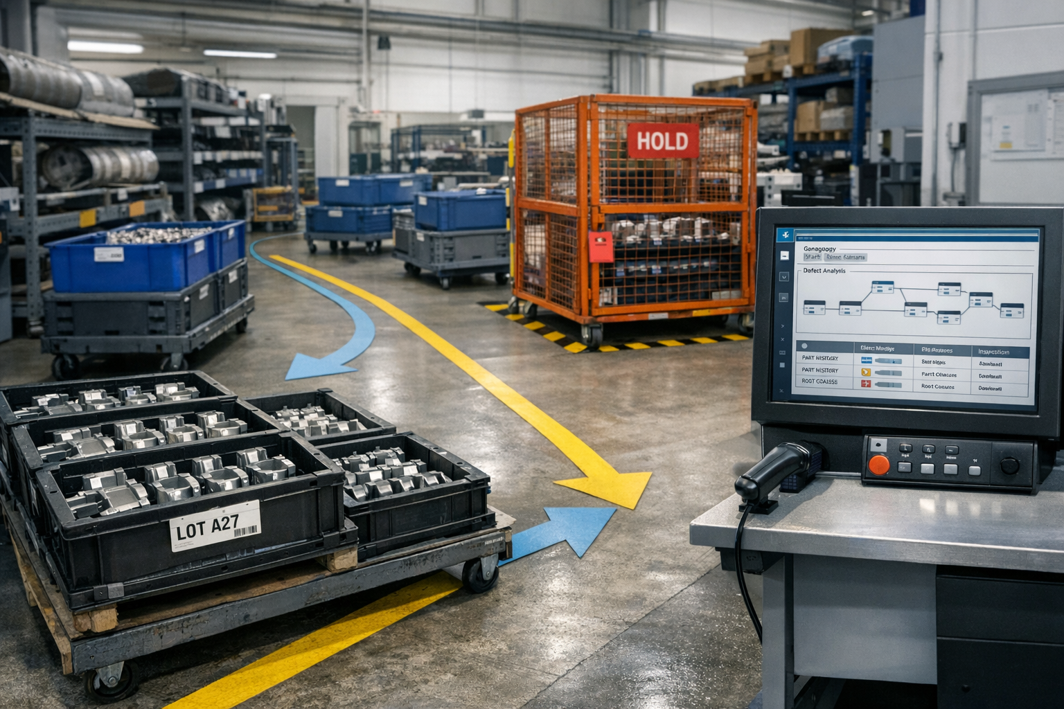
    • Automatic holds: Place affected work orders or serial numbers on hold when a serious deviation is detected, preventing further value-add until disposition.

    By intervening early, MES can stop defects before they multiply. Instead of discovering issues at final inspection—when multiple parts may already be affected—you can initiate corrective actions while only a small number of parts are at risk.

    Standard work enforcement and error-proofing

    Rework often stems from missed steps, incorrect settings, or inconsistent execution. MES can enforce standard work to reduce this variability:

    • Operation checklists that must be completed in sequence before moving to the next step.
    • Verification of tooling, fixtures, and programs (e.g., CNC program version, calibrated tool ID) before work starts.
    • In-process signoffs by operators and inspectors with clear accountability.
    • Embedded work instructions with visuals, parameters, and notes tailored to the specific configuration or revision.

    These capabilities do not replace training or certification, but they make it harder for common errors to slip through, especially when dealing with complex routings or multiple product variants on the same line.

    Material tracking and yield analytics

    Material waste in aerospace is often hidden. Offcuts, over-issues, and non-visible losses rarely show up in headline metrics. MES can help you understand and control this waste through:

    • Lot and serial tracking for high-value materials, linking each lot to specific work orders and operations.
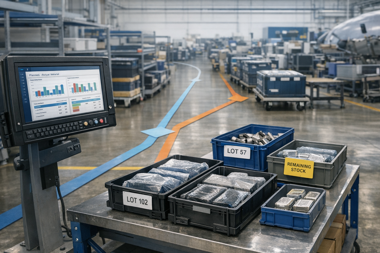
    • Actual vs. planned material usage at the operation or work-order level, not just net at the end of the job.
    • Yield reporting that shows how much input material results in conforming output across operations.

    With better data, engineering and operations can refine nesting strategies, cutting patterns, and process parameters. Over time, this moves decisions from rough assumptions to evidence-based optimization.

    Phased MES Rollout Strategy for Aerospace Plants

    Given aerospace regulatory and validation requirements, a “big bang” MES rollout is risky. A phased approach allows you to learn, adjust, and demonstrate value while maintaining control.

    Starting with a pilot line or product family

    Choose a pilot that is meaningful but manageable. Good candidates include:

    • A product family with significant scrap or rework issues.
    • A cell with relatively stable staffing and leadership support.
    • A value stream where both engineering and quality are engaged and available.

    In the pilot, focus on a limited set of high-impact MES use cases rather than attempting full functionality at once. For example, prioritize real-time monitoring at one special process, standardized work instructions for a critical assembly, and basic material tracking for expensive materials.

    Balancing speed with validation and compliance needs

    Aerospace environments must comply with customer, regulatory, and internal standards (for example, regarding software validation, configuration management, and data integrity). When planning your pilot:

    • Define which MES functions require formal validation before use in production.
    • Document configurations, workflows, and change controls from the start.
    • Use a test environment for training, configuration testing, and scenario validation before migrating to production.

    It is important not to underestimate the effort here. Validation and documentation add time, but they also build trust with quality and regulatory teams, which in turn helps smooth the path for broader adoption.

    Scaling to additional cells, plants, and suppliers

    Once the pilot demonstrates measurable waste reduction and stable operations, build a scale-out plan:

    • Standardize core templates for routes, work instructions, and data collection that can be reused across cells.
    • Capture lessons learned on change management, training, and configuration so future rollouts go faster.
    • Consider extending MES capabilities to key suppliers or integrating supplier data where appropriate to gain better visibility into upstream waste drivers.

    As you scale, maintain a clear priority on waste-reduction use cases so new deployments continue to deliver recognizable, quantifiable improvements.

    Change Management and Operator Adoption

    Even the best-designed MES will fail to reduce waste if people see it as extra work or surveillance rather than a tool that helps them succeed. Effective change management is essential.

    Communicating the purpose and benefits

    Frontline operators, inspectors, and technicians are closest to the process and will use MES every day. To gain their support:

    • Explain that the goal is preventing problems earlier, not blaming individuals for defects discovered late.
    • Highlight how MES can reduce rework loops, urgent expedites, and last-minute firefighting.
    • Show that better data will support more realistic process capability assessments and help justify needed investments in tooling, training, or equipment.

    Include operators and inspectors in design workshops and pilot reviews. Their insights often reveal practical ways to capture the right data with minimal disruption.

    Designing intuitive UIs and workflows

    To encourage adoption:

    • Keep screens simple and focused on the current task, avoiding unnecessary fields.
    • Use terminology and sequences that match how the work is actually performed on the floor.
    • Minimize manual entry where possible, using barcodes, RFID, or machine integration.
    • Provide clear visual indicators when something is out of tolerance or requires action.

    A small number of well-designed screens that accurately reflect real work will be more effective than a complex UI that attempts to handle every scenario from day one.

    Using early wins to build momentum

    After the pilot goes live, actively look for early signs that MES is helping reduce scrap, rework, or material waste. Examples include:

    • A parameter alert catches tool wear before it causes a run of non-conforming parts.
    • Standardized work instructions reduce rework on a complex assembly step.
    • Better material tracking reveals and corrects a recurring over-issue practice.

    Share these stories widely, backed by data. Recognize teams and individuals who contributed. Early success stories build credibility and help others see MES as a practical tool for improvement rather than a corporate mandate.

    Measuring and Communicating Impact

    To sustain support and funding, you must translate MES-enabled waste reductions into meaningful metrics and narratives for multiple audiences.

    Tracking scrap, rework, and material usage trends

    Define a small set of core metrics before go-live and measure them consistently over time. Typical examples include:

    • Scrap rate by part family, work center, and defect type.
    • Rework hours per unit or per month, by operation.
    • Material yield for key materials, comparing input mass or area to conforming output.
    • Time to detect critical defects (from introduction to detection).

    MES should make these metrics easier and faster to produce by providing consistent, structured data from the shop floor.

    Translating improvements into financial terms

    To communicate with executives and finance, connect operational improvements to financial impact. Examples include:

    • Annualized reduction in scrap write-offs for specific part families.
    • Reduced rework labor hours, expressed as capacity freed for value-add work.
    • Improved predictability of material usage, supporting more accurate costing and quoting.

    Be clear about assumptions and influencing factors. Instead of claiming a guaranteed payback period, present reasoned estimates and sensitivity to variables like volume, product mix, and future process changes.

    Sharing results with executives and customers

    Use dashboards, periodic reports, and simple before/after comparisons to show how MES contributes to performance. For customers and auditors, MES can demonstrate:

    • Enhanced traceability and control of special processes.
    • Systematic, data-driven approaches to reducing defects.
    • Evidence that corrective actions are effective and sustained.

    These capabilities can strengthen your position in bids, customer audits, and long-term partnership discussions, especially on programs where waste directly affects fixed-price margins.

    Sustaining Waste Reduction as a Continuous Improvement Program

    MES implementation is not a one-time project. To keep scrap, rework, and material waste trending down, you need an ongoing governance and improvement framework.

    Establishing governance and ownership

    Clarify who owns which aspects of MES and waste reduction:

    • Business process owners (operations, quality, engineering) define rules, workflows, and priorities.
    • IT or digital teams maintain the platform, integrations, and technical configuration.
    • Continuous improvement or Lean/Six Sigma teams use MES data to identify and close performance gaps.

    Set up a cross-functional steering group that regularly reviews MES performance, waste trends, and proposed changes.

    Regularly reviewing MES rules and configurations

    As processes change and new products are introduced, static MES configurations can become outdated. To prevent this:

    • Schedule periodic reviews of key alerts, holds, and data collection points.
    • Use MES data to refine control limits, inspection frequencies, and standard work steps.
    • Retire or simplify features that are not adding value or are causing unnecessary complexity.

    This ongoing tuning helps ensure MES continues to support waste reduction rather than becoming a rigid constraint.

    Integrating with Lean, Six Sigma, and quality programs

    MES and traditional improvement methodologies are complementary. MES provides the real-time, granular data that Lean and Six Sigma teams need to identify variation, validate improvements, and sustain gains. To integrate effectively:

    • Use MES data to populate value-stream maps, capability analyses, and control charts.
    • Build standard problem-solving workflows that reference MES data for root cause analysis.
    • Incorporate MES training into broader continuous improvement education for leaders and frontline staff.

    By treating MES as a core enabler of waste reduction as continuous improvement with MES in aerospace, you turn it from an IT project into a long-term competitive advantage.

    Conclusion

    Implementing MES in aerospace with a waste-reduction first mindset means starting from the real problems: costly scrap, limited rework options, hidden material losses, and schedule risk. By building a targeted business case, prioritizing high-impact use cases, rolling out in phases, and investing in change management, you can turn MES into a practical tool for preventing defects and protecting margins.

    With clear ownership and ongoing integration into continuous improvement programs, MES becomes a sustained capability for controlling waste in an environment where every gram of material and every minute of capacity matters.

  • Using MES Analytics to Reduce Material Usage Variance in Aerospace

    Using MES Analytics to Reduce Material Usage Variance in Aerospace

    Using MES Analytics to Reduce Material Usage Variance in Aerospace

    In aerospace manufacturing, material waste is never just a scrap problem—it is a financial event. High-cost alloys, forgings, and composite materials turn into immediate margin erosion when usage drifts beyond plan. Yet most of this waste does not come from dramatic failures. It comes from small, repeated variances that traditional systems struggle to see.

    Manufacturing Execution Systems (MES) can close this visibility gap. By capturing actual material consumption, scrap, and yield at each operation, MES enables detailed analytics on material usage variance. The result is practical insight into where waste is occurring, why it is happening, and which actions will deliver the greatest financial impact.

    This article explains how aerospace manufacturers can use MES analytics to track material usage variance, refine cost models, and support continuous improvement—without replacing existing ERP financial controls. For a broader view of scrap and rework, see our guide on material waste and cost visibility with MES in aerospace.

    The Financial Impact of Material Waste in Aerospace

    Aerospace programs are uniquely sensitive to material waste. Parts are often made from expensive, specialty materials and produced in low volumes with long cycle times. That combination makes even modest usage variance highly consequential.

    High-cost alloys, forgings, and composites

    Aerospace structures and engine components rely on titanium, nickel-based superalloys, advanced aluminum, and sophisticated composite systems. These materials are expensive to purchase, difficult to process, and sometimes subject to long lead times and strict qualification requirements.

    Material usage variance in this context has a disproportionate cost impact:

    • High raw material cost per part means that a few percentage points of over-consumption can outweigh labor savings.
    • Buy-to-fly ratios for complex machined parts are already high; unplanned waste further reduces effective yield.
    • Special process coupons and test samples add legitimate consumption, but lack of visibility can make them look like unexplained variance.

    Effect on fixed-price and long-term contracts

    Many aerospace manufacturers operate under fixed-price contracts, long-term agreements (LTAs), or rate-based pricing. When material costs rise during the life of a program, recovering those costs can be difficult or impossible.

    Material usage variance directly affects:

    • Program margin, especially on mature programs where price is stable but costs are still drifting.
    • Make-or-buy decisions, where inaccurate internal usage data can distort comparisons to supplier pricing.
    • Negotiations for future blocks or lots, where historical variance should be understood and either eliminated or built into pricing.

    Without clear visibility to actual usage, finance and program management are left to explain unfavorable variances based on averages and assumptions rather than data.

    Why ERP alone can’t see true usage variance

    ERP systems are essential for planning, purchasing, and financial control. However, they are typically not designed to capture detailed, operation-level material usage:

    • Backflush at completion only: Many ERPs backflush material when an operation or order is completed, not when material is actually consumed.
    • Limited scrap categorization: ERP may record scrap quantities and value, but rarely captures enough context (operation, cause, shift) for root-cause analysis.
    • Coarse granularity: ERP tends to operate at the work-order or item level, not the individual serial number, lot, or operation-step level that aerospace traceability demands.

    Because of these limitations, ERP is excellent for valuing material but less effective at explaining where and why additional consumption occurs. MES fills this gap by capturing execution data as work happens.

    How MES Captures Actual Material Consumption

    MES connects people, machines, and materials at the point of execution. That makes it the ideal system to track real material usage and feed analytics on variance.

    Issuing and backflushing material to operations

    In a MES-enabled aerospace environment, material is typically associated with work as it moves through the routing:

    • Material issue at operation start: Operators scan barcodes or RFID tags to issue kits, panels, forgings, or raw stock to a specific operation.
    • Backflushing on consumption: For repetitive or predictable usage, MES can backflush material based on actual production quantities at that step, rather than only at order completion.
    • Partial usage: The system can record partial consumption of a panel, bar, or sheet and track the remaining remnant for reuse.

    This approach links specific material lots and quantities to operations and work centers, enabling much finer-grained variance analysis.

    Tracking scrap and yield at each step

    MES records what happens to material as parts move through the process:

    • Scrap events logged with reason codes (e.g., machining oversize, layup defect, cure failure).
    • Rework and repair recorded with additional material usage where allowed by engineering.
    • Yield calculation at each operation, not just at final inspection.

    The combination of issued material, good output, rework, and scrap enables MES to calculate actual yield by operation and by part, highlighting where material is being lost.

    Serial, lot, and heat-level traceability

    Aerospace programs often require traceability down to heat, lot, or individual serial numbers. MES supports this by:

    • Associating each part serial with the specific material lots and heats used in its manufacture.
    • Tracking consumables and process materials (e.g., adhesives, prepregs, fasteners) where they materially affect cost or quality.
    • Linking inspection results and process parameters to both part and material identifiers.

    This level of traceability not only supports regulatory and customer requirements, it also provides the dataset needed to analyze material usage variance across programs, lots, and suppliers.

    Reporting Actual vs Planned Usage by Part and Operation

    Once MES is reliably capturing material consumption and scrap, the next step is to compare it to the planned picture in your BOMs and routings.

    Comparing to standard routings and BOMs

    The core of material usage variance analysis is a comparison between:

    • Planned usage: Quantities defined in ERP or PLM bills of material, including scrap factors and allowances.
    • Actual usage: Quantities consumed and scrapped as recorded by MES at each operation.

    To enable this comparison, MES and ERP must share common item numbers, units of measure, and revision identifiers. With that alignment in place, MES analytics can produce reports such as:

    • Planned vs. actual material per part number and revision.
    • Variance per operation (e.g., rough machining vs. final machining vs. assembly).
    • Usage variance for specific materials across multiple part numbers.

    Identifying chronic over-consumption

    Not all variance is random. MES analytics can reveal chronic patterns of over-consumption, for example:

    • Certain work centers consistently consuming more composite material per panel.
    • Specific fixtures or tools associated with higher trim or machining scrap.
    • Programs where legacy allowances significantly underestimate actual material needs.

    By filtering data over weeks or months, you can distinguish between isolated incidents and systemic issues that warrant engineering or process changes.

    Understanding process-driven vs random variation

    MES data helps separate process-driven variance from genuine randomness by correlating usage with:

    • Operation and work center: Is variance localized to a step or spread across the route?
    • Shift and crew: Do certain shifts use more material due to experience levels or local workarounds?
    • Material batch or supplier: Does material source affect trim requirements, yield, or defect rates?

    Clarify the operational risk

    When the work behind Using MES Analytics to Reduce affects quality, delivery, or compliance, teams need one place to connect evidence, decisions, and shop-floor follow-through.

    Map the risk in Using MES Analytics to Reduce

    Patterns in this data indicate whether you should focus on process controls, training, supplier management, or BOM assumptions.

    Analyzing Scrap Drivers with MES Data

    Material usage variance often originates in scrap and rework. MES provides the depth of data needed to understand these drivers and prioritize corrective actions.

    Correlating scrap with work center, shift, and supplier

    Because MES ties scrap to specific operations, people, and materials, you can build analyses such as:

    • Scrap cost by work center, highlighting the most expensive points of failure.
    • Scrap rate by shift or crew, identifying training or staffing gaps.
    • Scrap by material lot or supplier, exposing quality or stability issues in the supply base.

    These insights go beyond simple scrap percentages, providing a basis for targeted improvement projects and supplier discussions.

    Spotting patterns in rework-driven material loss

    Rework often appears to save parts, but it can quietly increase material consumption through additional cutting, patching, or component replacement. MES can show:

    • How often rework leads to additional material usage (e.g., extra plies, shims, or hardware).
    • Which rework paths have the highest cost per saved part.
    • Operations where rework frequently fails, ultimately resulting in scrap.

    With this view, engineering and operations can determine when it is better to invest in first-pass yield improvements rather than relying on rework.

    Differentiating unavoidable trim from avoidable scrap

    Some material loss is inherent in aerospace manufacturing. Examples include:

    • Trim allowances for composite layups.
    • Starter stock for machining complex shapes.
    • Mandatory test coupons and process validation pieces.

    MES data helps differentiate this unavoidable trim from avoidable scrap by quantifying each type and mapping it to process steps. Over time, you can refine BOM scrap factors to reflect realistic, stable levels of unavoidable loss while targeting the remainder for reduction.

    Using Insights to Improve Processes and Cost Models

    Collecting data is only half the job. The real value of MES analytics is realized when insights drive concrete changes in processes and financial models.

    Refining allowances and scrap factors

    Legacy BOMs often contain conservative scrap factors or outdated assumptions. Using MES data, you can:

    • Update scrap factors by part family and operation based on recent, stable performance.
    • Right-size material allowances (e.g., panel size, bar length, ply count) to better match actual needs.
    • Separate regulatory-mandated scrap (e.g., coupons) from process-driven waste.

    This alignment improves standard costing, quoting accuracy, and program financial forecasts.

    Prioritizing continuous improvement projects

    Not every variance justifies an improvement project. MES analytics support rational prioritization by showing:

    • Scrap cost per operation and per work center.
    • Material usage variance per part number, ranked by annual spend.
    • Trend lines that distinguish worsening performance from stable, predictable variance.

    With this information, engineering and operations teams can focus limited resources on the few processes that drive most of the excess material cost.

    Collaborating with finance and program management

    Material usage variance is as much a financial topic as an engineering one. Effective MES usage supports collaboration by providing:

    • Common reports that tie together engineering scrap causes and financial impact.
    • Scenario analysis for “what if” questions (e.g., what happens to program margin if we improve yield by 2% at a specific operation?).
    • Evidence for price negotiations when unavoidable material costs differ significantly from original assumptions.

    Importantly, MES should be positioned as complementary to ERP—providing the operational detail needed to understand and influence the financial results that ERP records.

    Practical Dashboard and KPI Examples

    To turn MES data into action, aerospace manufacturers typically deploy focused dashboards and KPIs around material usage and scrap.

    Material yield by part family

    A useful starting view is material yield by part family or product line. A dashboard might show:

    • Planned vs. actual material per completed unit.
    • Yield trends by month or production lot.
    • Highlighting of families with the largest negative variance.

    This keeps attention on groups of parts where improvements will have significant aggregate impact.

    Scrap cost by process step

    Another powerful view is scrap cost by process step, not just by scrap quantity. This should include:

    • Material cost of scrapped parts and assemblies.
    • Additional material consumed in rework operations.
    • Drill-down capabilities from total cost to specific part numbers and work centers.

    By ranking process steps by scrap cost, organizations can quickly identify “hot spots” worth investigation.

    Top offenders by work center or program

    MES dashboards aimed at leaders often include “top offenders” lists, such as:

    • Work centers with the highest material usage variance this quarter.
    • Programs where actual usage significantly exceeds quoted assumptions.
    • Part numbers responsible for most of the variance in a given work cell.

    Connect decisions to execution

    Connect 981 helps turn this kind of operational detail into traceable action, so the context behind each decision does not get lost.

    Discuss the workflow for Using MES Analytics to Reduce

    These views promote accountability and support structured problem-solving, rather than relying on anecdotes or isolated incidents.

    Governance and Data Quality Considerations

    The value of MES analytics depends on data quality. Governance practices are essential to ensure the numbers can be trusted and used for decisions.

    Ensuring operators record scrap accurately

    Operator engagement is critical. To achieve reliable data without slowing production:

    • Design simple, quick scrap entry screens with clear reason codes.
    • Use mandatory fields only where they drive tangible value (e.g., operation, reason, quantity, disposition).
    • Provide feedback loops by sharing reports that show how the data is used to improve processes, not just monitor performance.

    Training should emphasize that accurate reporting protects programs and jobs by preventing unpleasant financial surprises later.

    Aligning MES and ERP material definitions

    For variance analytics to make sense, MES and ERP must speak the same language. Key alignment points include:

    • Item numbers and revisions used consistently in both systems.
    • Units of measure (e.g., kg vs. lb, sheet vs. m2) aligned or converted transparently.
    • Material groups and cost buckets mapped so MES reports can roll up to financial categories.

    Data integration should be designed so that planners and engineers do not need to maintain parallel structures in multiple systems.

    Handling rework, re-melt, and recovery flows

    Aerospace manufacturing often includes specialized material flows such as rework, re-melt, and recovery of scrap material. MES configurations should clarify:

    • When rework consumes additional material versus simply adding labor.
    • How recovered material (e.g., re-melted ingots, reclaimed test pieces) is credited back into inventory and reflected in variance calculations.
    • Which scrap streams are truly lost and should be fully burdened with material cost.

    Clear rules ensure that variance reporting fairly represents both waste and legitimate recovery activities.

    Bringing It All Together

    Reducing material usage variance in aerospace is a continuous effort, not a one-time project. MES analytics provide the factual foundation for that effort by:

    • Capturing actual material usage, scrap, and yield at each operation.
    • Comparing real performance to planned BOMs and routings.
    • Highlighting where waste is concentrated and where process improvements will protect margins.

    When combined with disciplined governance and close collaboration between operations, engineering, and finance, MES becomes a powerful enabler of margin protection and competitive pricing in demanding aerospace programs.

    To see how material variance fits into the broader picture of scrap and rework reduction, explore our hub article on reducing scrap, rework, and material waste in aerospace manufacturing with MES.

    For teams putting this topic into daily operation, work orders and digital travelers, shop floor execution control, a connected execution platform help connect the concept to traceability, work-order reality, and audit-ready evidence.

    This article is for aerospace operations, quality, and compliance teams who need to understand Using MES Analytics to Reduce Material Usage Variance in Aerospace. It explains the practical question this topic answers in a manufacturing execution context.

    The same operating model also depends on Connect 981’s aerospace execution solutions, real aerospace execution examples, Connect 981’s aerospace operations guidance, practical aerospace operations FAQs, especially when decisions have to move across quality, production, suppliers, and program leadership without losing context.

  • Using MES to Enforce Standard Work and Error-Proof Aerospace Operations

    Using MES to Enforce Standard Work and Error-Proof Aerospace Operations

    Using MES to Enforce Standard Work and Error-Proof Aerospace Operations

    In aerospace manufacturing, small deviations from standard work can have outsized consequences. A missed torque check, an out-of-date work instruction, or a skipped in-process inspection can mean scrapped high-value components, expensive rework, and potential escapes to the customer. Manufacturing Execution Systems (MES) give aerospace plants the tools to embed standard work directly into the workflow, so errors are prevented at the point of execution instead of discovered at final inspection.

    This article explains how MES can serve as the digital backbone for standard work in aerospace, how it enables practical error-proofing on the shop floor, and how it directly supports waste reduction, rework prevention, and regulatory compliance.

    Why Standard Work Breaks Down in Aerospace Shops

    Aerospace organizations typically invest heavily in procedures, work instructions, and training. Yet rework, scrap, and nonconformances still occur. The issue is rarely a lack of documented standard work, but rather breakdowns in how that standard work is delivered and followed in real time.

    Paper travelers and outdated instructions

    Many aerospace shops still rely on paper travelers, printed work instructions, and binders at workstations. This creates several problems:

    • Version confusion: Operators may unknowingly work from obsolete prints or instructions when new revisions are released after a traveler is printed.
    • Slow updates: Engineering changes can take days or weeks to propagate to all affected jobs, especially across multiple sites.
    • Limited context: Paper instructions often lack embedded visuals, 3D models, or video that would clarify complex steps.
    • Traceability gaps: Handwritten notes and check marks are hard to interpret later and may not meet customer or regulatory audit expectations.

    These issues increase the risk that an operator will follow an outdated or incomplete version of the standard work, creating variability and potential nonconformance.

    Complex routings and engineering changes

    Aerospace routings are complex. Parts may move through dozens or even hundreds of operations, often with special processes (e.g., heat treatment, NDT, coatings) and outsourced steps. Configuration changes and engineering revisions are frequent, especially on development programs and early production.

    In this environment, breakdowns occur when:

    • Route steps are added, removed, or reordered without clear guidance on when the new route applies.
    • Special-process parameters change (e.g., oven soak times, pressure limits) without synchronized updates to work instructions and data collection forms.
    • Different serial numbers within the same batch require different processing due to design changes or concessions, but the traveler does not clearly differentiate them.

    Without a digital system of record, operators and supervisors must rely on memory, printed emails, or ad-hoc workarounds that deviate from standard work.

    Training gaps and shift-to-shift variation

    Even with strong training programs, aerospace shops face:

    • Turnover and ramp-up: New hires and temporary workers may not internalize procedures quickly.
    • Informal shortcuts: Experienced operators may adopt their own methods over time, drifting away from documented standards.
    • Shift variation: Night and weekend shifts may follow different practices than dayshift if support and supervision differ.

    Training and competency management remain critical, but they are not enough on their own. MES complements training by embedding standard work into the workflow so that the correct steps are visible and enforced at the moment of execution.

    MES as the System of Record for Standard Work

    An MES can act as the single, controlled source of truth for how work should be performed on the shop floor. Instead of relying on static documents, standard work becomes a living, digital model executed through the system.

    Version-controlled electronic work instructions

    In a robust aerospace MES, electronic work instructions (eWIs) are maintained with formal revision control:

    • Each instruction set is tied to a specific part number, operation, and revision.
    • Approvals and release workflows ensure that only validated content reaches the shop.
    • Prior versions are archived for traceability but cannot be used on active jobs.

    On the floor, operators access eWIs from terminals or tablets. They see the correct version automatically, complete with photos, annotated drawings, and step-by-step guidance. When engineering updates an instruction, the MES can route it through review and release, then push it live without reprinting and redistributing paper.

    Linking routings to part numbers and revisions

    Standard work is more than instructions for a single operation; it is also the routing that defines the correct sequence of operations and resources. MES supports this by:

    • Associating routings with specific part numbers, configurations, and effectivity dates.
    • Aligning each operation step with the appropriate eWI, NC program, tooling list, and inspection plan.
    • Managing alternate routings (e.g., for rework, different machine groups, or subcontract operations) under controlled rules.

    This linkage ensures that when a work order is released, it automatically inherits the correct route and work instructions based on the part revision and configuration.

    Ensuring only approved processes are executed

    Because MES knows which instructions, routings, and process parameters are approved, it can actively prevent unapproved work:

    • Blocking the start of an operation if the instruction set is not released.
    • Restricting use of an NC program or recipe that is superseded or not qualified for the part.
    • Highlighting when a critical resource (e.g., calibrated gage, certified operator, qualified machine) is missing or not approved.

    This moves standard work from being a passive reference document to an enforced, system-driven behavior.

    Error-Proofing Techniques Enabled by MES

    Error-proofing in aerospace does not mean eliminating the need for skilled operators or training. Instead, it means designing processes and systems so that common mistakes are harder to make and easier to detect immediately. MES provides several capabilities that directly support error-proofing at the point of execution.

    Mandatory data fields and input validation

    Data collection is central to aerospace compliance and quality. MES can structure this data entry to reduce errors:

    • Required fields: Operators cannot complete an operation without entering mandatory values (e.g., torque, temperature, batch/lot numbers, inspector ID).
    • Range checks: Collected values are automatically checked against allowable limits; out-of-range entries trigger warnings or holds.
    • Format and logic validation: Serial numbers, lot codes, and other identifiers can be validated for correct format and checked against approved lists.
    • Context-based prompts: MES can display guidance when data trends indicate risk (e.g., trending toward upper tolerance), helping operators adjust before defects occur.

    By structuring data entry, MES reduces transcription errors and ensures that critical process parameters conform to standard work.

    Sequence enforcement and sign-offs

    In many aerospace operations, the order of steps is as important as the steps themselves. MES can enforce the correct sequence by:

    • Presenting steps in the required order and preventing skipping ahead.
    • Requiring electronic sign-off (with user credentials and timestamps) at key checkpoints.
    • Requiring dual sign-off or independent inspection for high-criticality steps.

    This helps ensure that operators do not bypass inspections, torque checks, or cleaning operations under time pressure. The system can prevent completion of an operation until all mandatory sign-offs are captured.

    In-line checks and conditional prompts

    Instead of relying solely on end-of-operation verification, MES enables in-line checks embedded within the workflow:

    • Prompting for measurements after specific sub-steps, not just at the end of the operation.
    • Triggering additional checks when certain conditions are met (e.g., a batch from a new supplier, a part with known risk features).
    • Integrating machine and test data automatically, reducing the chance of misrecording readings.

    Clarify the operational risk

    When the work behind Using MES to Enforce Standard affects quality, delivery, or compliance, teams need one place to connect evidence, decisions, and shop-floor follow-through.

    Map the risk in Using MES to Enforce Standard

    These embedded checks help detect deviations early, before additional value is added to the part, reducing both rework and scrap.

    Reducing Rework with First-Time-Right Execution

    Rework is especially costly in aerospace, due to high material value, long cycle times, and strict limitations on repair. MES-driven standard work and error-proofing aim to maximize first-time-right execution.

    Catching missing steps before moving to the next operation

    Traditional quality controls often detect issues only at final inspection or after several operations have been completed. MES changes this by:

    • Preventing the closure of an operation until all required steps, measurements, and sign-offs are complete.
    • Flagging missing or inconsistent data when an operator attempts to move a part forward.
    • Using visual dashboards to show supervisors which operations are blocked and why, enabling quick support.

    By stopping the part at the source of the issue, the plant avoids compounding the mistake across multiple downstream operations.

    Preventing unauthorized rework and deviations

    In time-pressured environments, informal rework or on-the-spot adjustments can creep in. MES helps control this by:

    • Defining approved rework routings and repair limits, including required inspections.
    • Requiring digital approval for deviations and concessions before rework can proceed.
    • Blocking ad-hoc changes to the standard route without proper authorization and documentation.

    This ensures that all rework is traceable, approved, and executed under controlled instructions, protecting both product integrity and compliance obligations.

    Ensuring proper material, tooling, and programs are used

    Many aerospace nonconformances stem from using the wrong material batch, tooling setup, or NC program. An integrated MES can mitigate these risks:

    • Linking each work order to specific material lots and enforcing lot selection rules at issue.
    • Checking that calibrated tools and gages are within date and appropriate for the required tolerance.
    • Verifying that the selected NC program and machine setup match the current part configuration and revision.

    These checks help ensure that operators have the right inputs to execute standard work correctly the first time, reducing both rework and the risk of scrap.

    Supporting Engineering Changes and Configuration Control

    Aerospace programs live under strict configuration control. Changes must be applied precisely to the correct parts, with full traceability. MES plays a central role in keeping standard work aligned with engineering intent as designs evolve.

    Propagating updated instructions to active orders

    When engineering releases a change, MES can:

    • Update routings and eWIs tied to the affected part numbers and revisions.
    • Identify active work orders impacted by the change and determine if they must be reworked, held, or allowed to proceed.
    • Push updated instructions to operators in real time, reducing lag between design decision and shop-floor execution.

    This minimizes the risk that parts are built to a superseded configuration and supports more agile engineering changes without uncontrolled variability.

    Handling grandfathered parts and mixed configurations

    Many aerospace lines run mixed configurations: some units built to the old standard, some to the new. MES can support this complexity by:

    • Associating each serial number with a specific configuration and effectivity date.
    • Automatically presenting the correct routing and instructions based on that configuration, even at the same workstation.
    • Flagging when an operator attempts to apply the wrong configuration or process to a part.

    This level of control is difficult to achieve with paper-based systems and is essential for preventing configuration-related rework and escapes.

    Auditability for customers and regulators

    Aerospace customers and regulators expect clear evidence that standard work was followed and that configuration control was maintained. MES strengthens audit readiness by:

    • Providing electronic records of every operation, sign-off, measurement, and deviation.
    • Linking data to specific parts, serial numbers, and configurations.
    • Enabling rapid retrieval of historical instruction versions and the dates they were in effect.

    These capabilities support certification activities, customer audits, and root-cause investigations while reducing the manual effort of assembling documentation.

    Change Management for Operators and Supervisors

    Digitizing standard work with MES is not just a technology project; it is a change in how people work. Success depends on involving end users and addressing concerns about pace, autonomy, and usability.

    Involving end users in instruction design

    The most effective eWIs are built with operator input:

    • Capturing tribal knowledge and proven best practices from experienced staff.
    • Piloting new instructions with a small group before widespread rollout.
    • Creating feedback loops so operators can suggest improvements based on real-world experience.

    This approach improves accuracy, buy-in, and the usability of digital standard work.

    Training on digital terminals and MES UIs

    Introducing MES often requires new skills:

    • Navigating digital instructions and entering data at terminals.
    • Understanding visual indicators, alerts, and workflows in the user interface.
    • Following electronic sign-off processes instead of paper signatures.

    Connect decisions to execution

    Connect 981 helps turn this kind of operational detail into traceable action, so the context behind each decision does not get lost.

    Discuss the workflow for Using MES to Enforce Standard

    Structured training and coaching are essential; MES does not replace the need for formal training and competency management. Instead, it reinforces training by consistently presenting and enforcing the correct steps.

    Addressing concerns about pace and autonomy

    Some operators may worry that MES will slow them down or remove their judgment. Effective change management should:

    • Show how MES can reduce rework, re-inspections, and firefighting, making work more predictable.
    • Clarify where operator discretion is still vital, especially in problem-solving and continuous improvement.
    • Use metrics to demonstrate that, after initial adjustment, digital standard work can support stable or even improved throughput.

    By positioning MES as a support tool rather than a surveillance mechanism, organizations can foster adoption and sustained use.

    Measuring the Impact on Rework and Scrap

    To justify investment and guide continuous improvement, aerospace plants need to quantify how MES-driven standard work and error-proofing impact rework, scrap, and overall waste.

    Tracking rework rates by operation and work center

    MES provides granular visibility into where defects originate:

    • Capturing nonconformance and rework data at the specific operation where issues are found.
    • Aggregating rework rates by part family, work center, shift, and operator group.
    • Highlighting operations with recurring deviations from standard work.

    These insights allow quality and manufacturing engineering teams to prioritize improvements where they will have the greatest impact.

    Comparing defect profiles before and after MES rollout

    To evaluate the effectiveness of MES error-proofing, organizations can:

    • Establish baseline rework, scrap, and defect rates prior to MES deployment.
    • Track trends after digitizing standard work and introducing sequence controls, validations, and in-line checks.
    • Analyze how specific MES features (e.g., mandatory fields, routing enforcement) correlate with reductions in certain defect types.

    This data-driven approach helps tune both the MES configuration and the underlying standard work content.

    Highlighting high-impact standard work improvements

    MES makes it easier to test and validate changes to standard work:

    • Rolling out revised instructions to a pilot cell and monitoring quality and cycle time.
    • Comparing defect types and frequencies before and after instruction changes.
    • Scaling successful patterns across similar parts or lines.

    Over time, this capability supports a continuous-improvement loop that reduces waste and strengthens process capability across the plant.

    Connecting Standard Work to Broader Waste Reduction

    Digital standard work and error-proofing are core components of a broader MES strategy to reduce scrap, rework, and material waste across aerospace operations. When combined with real-time monitoring of process parameters and in-process quality checks, MES helps detect problems earlier and prevent defects from multiplying across batches and operations.

    To explore how these capabilities fit into a larger waste-reduction approach—including material usage tracking, trend analysis, and margin protection in fixed-price contracts—see our overview on reducing rework with MES in aerospace manufacturing.

    For teams putting this topic into daily operation, work orders and digital travelers, shop floor execution control, a connected execution platform help connect the concept to traceability, work-order reality, and audit-ready evidence.

    This article is for aerospace operations, quality, and compliance teams who need to understand Using MES to Enforce Standard Work and Error-Proof Aerospace Operations. It explains the practical question this topic answers in a manufacturing execution context.

    The same operating model also depends on Connect 981’s aerospace execution solutions, real aerospace execution examples, Connect 981’s aerospace operations guidance, practical aerospace operations FAQs, especially when decisions have to move across quality, production, suppliers, and program leadership without losing context.

  • How Real-Time MES Monitoring and Alerts Reduce Scrap in Aerospace Manufacturing

    How Real-Time MES Monitoring and Alerts Reduce Scrap in Aerospace Manufacturing

    Scrap in aerospace manufacturing is more than a quality problem—it is a financial event. Losing a single high-value forging, composite layup, or machined structure can erase the margin on an entire order and ripple through delivery schedules and customer commitments.

    Most of that waste does not come from dramatic failures. It comes from small process deviations that quietly accumulate between inspections. Real-time monitoring and alerts in a Manufacturing Execution System (MES) give aerospace plants a way to detect those deviations early, intervene before scrap multiplies, and protect throughput and on-time delivery.

    This article explains which parameters to monitor, how to design effective alerts, and how to respond when MES detects a problem—all with a focus on real time MES monitoring in aerospace environments.

    For a broader view of how MES cuts scrap and waste across the value stream, see our guide on waste reduction with MES in aerospace manufacturing.

    The Cost of Late Detection in Aerospace Production

    High-value materials and long cycle times

    Aerospace parts often combine expensive materials, complex routings, and long cycle times. When a defect is found late—for example, at final inspection—you are not just scrapping material. You are discarding:

    • Machine time and labor across multiple operations
    • Consumables, tooling life, and utilities
    • Occupied capacity that could have produced good parts

    In some programs, rework is tightly controlled or prohibited entirely. A nonconformance discovered late can mean a total loss, plus the cost of expediting a replacement.

    Impact on delivery schedules and customer commitments

    When defects are found only at end-of-line inspection, the recovery path usually involves:

    • Re-planning production to squeeze in replacement parts
    • Premium freight for materials or finished goods
    • Negotiations around missed milestones or penalty clauses

    Because cycle times are long, there may be no quick way to replace scrapped parts without displacing other work. This erodes customer confidence and increases program risk.

    Hidden rework and unplanned capacity consumption

    Even when parts can be saved, rework often hides the real cost of late detection. Rework consumes:

    • Engineering time to evaluate dispositions and concessions
    • Quality resources for additional inspections and documentation
    • Production capacity that should be producing conforming parts

    Without good traceability and real-time visibility, these costs can be buried in overhead. MES exposes this waste and, more importantly, helps prevent it by catching deviations as soon as they appear.

    Core MES Capabilities for Real-Time Monitoring

    Collecting process and quality data at the operation level

    Real-time MES monitoring in aerospace starts with data collection at the point of execution. This typically includes:

    • Process parameters (temperatures, pressures, speeds, feeds, flows, times)
    • Machine and cell status (run, idle, fault, setup, changeover)
    • In-process inspection results (dimensional checks, NDT results, visual inspections)
    • Operator inputs (checklists, confirmations, defect codes, comments)

    The MES associates this data with specific work orders, serial numbers, and operations. That traceability is crucial in aerospace, where requirements from customers and regulators demand clear evidence of how each part was produced.

    Defining control limits and tolerance bands

    To enable real-time monitoring, the MES needs to know what “good” looks like. This usually involves:

    • Nominal values for process parameters (e.g., target temperature or torque)
    • Specification limits from engineering drawings or process sheets
    • Control limits or tighter warning bands based on historical performance

    In many aerospace operations, especially special processes like heat treatment, coating, or bonding, the acceptable window may be narrow. The MES compares incoming data against these configured limits in real time and generates events when something drifts or crosses a boundary.

    Event-driven alerts vs. periodic reports

    Traditional quality systems often rely on daily or weekly reports, or batch uploads from machines. By the time someone analyzes the data, defects may already have multiplied.

    With real-time MES monitoring:

    • Event-driven alerts fire immediately when a rule is violated (e.g., a temperature exceeds its upper limit).
    • Trend-based notifications can indicate drift before a parameter leaves its tolerance band.
    • Dashboards show current status at the line, cell, or plant level for supervisors and engineers.

    Periodic reports still have value for analysis and improvement, but the primary protection against scrap comes from event-driven, in-the-moment feedback.

    Choosing What to Monitor in Aerospace Processes

    Critical-to-quality (CTQ) characteristics

    Not every parameter warrants a real-time alert. In aerospace, a practical starting point is to focus on critical-to-quality (CTQ) characteristics—those with the highest impact on safety, performance, and compliance. Examples include:

    • Key dimensions on flight-critical or rotating components
    • Bond-line thickness in composite assembly
    • Heat treatment profiles for structural alloys
    • Coating thickness and cure profiles on corrosion-critical surfaces

    By mapping CTQs to process steps in the MES, you can ensure that critical characteristics are measured, recorded, and monitored continuously where it matters most.

    Environment, tool, and setup variables

    Many defects originate not from the part itself but from its environment and setup. Real-time MES monitoring can track:

    • Ambient conditions (temperature, humidity) for processes where they affect cure, adhesion, or dimensional stability
    • Tooling and fixture status (tool life, calibration dates, fixture ID and verification)
    • Setup verification (correct program loaded, correct tooling loaded, correct material and revision)

    By alerting on these factors, the MES can catch problems like out-of-calibration tools, incorrect fixtures, or misconfigured programs before they impact multiple parts.

    Inspection results and operator inputs

    Inspection and operator feedback are often early indicators of problems. An effective MES will:

    • Capture in-process inspection results directly at the station
    • Compare those values to drawing tolerances or control limits
    • Allow operators to flag suspected issues or enter defect codes

    When an operator reports a recurring defect or borderline measurement, the MES can trigger alerts to quality and engineering, initiating investigation before the issue spreads.

    Designing Effective MES Alerts

    Thresholds, trends, and rule-based logic

    Effective alerts in aerospace MES implementations are rarely based on a single hard threshold. Common patterns include:

    • Limit violations: A parameter crosses a high or low limit.
    • Trend detection: A sequence of measurements shows consistent drift in one direction.
    • Rule-based logic: Combinations of conditions (e.g., “IF temperature is high AND dwell time is short THEN alert”).

    Clarify the operational risk

    When the work behind How Real-Time MES Monitoring and affects quality, delivery, or compliance, teams need one place to connect evidence, decisions, and shop-floor follow-through.

    Map the risk in How Real-Time MES Monitoring and

    Trend and rule-based alerts are especially useful for catching issues early, when parameters are still technically in tolerance but migrating toward an out-of-spec condition.

    Prioritizing alerts by risk and cost of failure

    Not all alerts are equal. To keep focus on what matters most, aerospace plants typically tier alerts, such as:

    • Critical: Potential impact on safety-of-flight or regulatory compliance; requires immediate action and often an automatic hold.
    • High: Likely to result in scrap or major rework if not addressed promptly.
    • Medium/Low: Early warnings, trends, or minor deviations that can be addressed in routine reviews.

    Prioritization helps ensure that the most serious issues are impossible to ignore while less urgent signals are still visible but not disruptive.

    Avoiding alert fatigue among operators and engineers

    Alert fatigue occurs when personnel receive so many notifications that they begin to ignore or routinely dismiss them. To avoid this in real time MES monitoring for aerospace:

    • Limit alerts on non-critical parameters; use dashboards or periodic summaries instead.
    • Consolidate related conditions into a single alert event when possible.
    • Set sensible deadbands or timers so alerts do not repeatedly fire for minor oscillations.
    • Review alert volumes regularly; disable or tune rules that generate frequent but low-value notifications.

    Well-designed alerts should be meaningful, actionable, and rare enough that operators treat them as important signals, not background noise.

    Workflow After an Alert: From Response to Resolution

    Automatic holds on work orders and lots

    When an alert indicates a potential nonconformance, speed matters. MES can automatically:

    • Place the affected lot, serial number, or work order on hold
    • Prevent further processing or shipment until evaluation is complete
    • Flag related parts that went through the same operation or setup window

    This containment limits exposure while engineers and quality teams investigate. Automatic holds are especially important when the suspected issue involves flight-critical components or special processes.

    Guided troubleshooting steps in MES

    To avoid ad-hoc responses, aerospace MES workflows often provide:

    • Standard response plans linked to specific alert types
    • Checklists for operators and technicians (e.g., verify tooling, confirm program version, inspect fixture)
    • Data capture forms for documenting findings, measurements, and interim actions

    By embedding troubleshooting guidance directly in the MES, plants can shorten response times and ensure that corrective actions are consistent and well documented.

    Documentation and learning from each event

    Every alert is an opportunity to strengthen the process. MES can support continuous improvement by:

    • Capturing the root cause analysis and final disposition
    • Linking alerts to corrective and preventive actions (CAPA)
    • Tracking how often specific alerts occur and how they are resolved

    Over time, this history helps engineers refine limits, update work instructions, and improve equipment maintenance plans—gradually reducing both scrap and the frequency of serious alerts.

    Case Examples: Catching Scrap Before It Scales

    Detecting thermal profile drift in heat treatment

    Consider a heat treatment furnace used for structural alloy components. The MES continuously records:

    • Zone temperatures at defined intervals
    • Soak times and ramp rates
    • Load details (part numbers, quantities, locations)

    Alert rules watch for trends where one zone begins to underperform relative to others. Before any run actually violates specification limits, the MES detects a pattern of slow drift and notifies engineering. The result:

    • Maintenance can investigate the heating elements and controls.
    • Potential nonconformances are caught before multiple loads are affected.
    • Scrap risk is reduced without stopping the furnace unnecessarily.

    Catching mis-loaded programs in machining cells

    In a flexible machining cell, each part number requires a specific NC program and tooling setup. The MES integrates with the machine controllers to verify:

    • Correct program revision is loaded for the scheduled part
    • Tool list matches the approved setup for that operation
    • Offsets and work coordinates are within expected ranges

    If an operator attempts to start a cycle with a mismatched program, the MES generates an alert and prevents machining from starting. This avoids the scenario where dozens of high-value parts are machined with an incorrect revision before anyone notices at inspection.

    Identifying out-of-spec surface treatment conditions

    Surface treatments such as anodizing, coating, or plating are common special processes in aerospace. MES can monitor:

    • Bath chemistry (concentration, pH, conductivity)
    • Temperature and agitation parameters
    • Exposure times for each rack or part

    Connect decisions to execution

    Connect 981 helps turn this kind of operational detail into traceable action, so the context behind each decision does not get lost.

    Discuss the workflow for How Real-Time MES Monitoring and

    When any parameter trends toward the edge of its allowable range, the MES issues alerts to operators and process engineers, who can perform corrective actions such as adjusting chemistry or scheduling tank maintenance. This reduces the chance that large batches of parts will require stripping and reprocessing or, in the worst case, scrapping.

    Governance and Continuous Improvement of Alert Rules

    Tuning limits based on historical data

    Initial MES alert limits are often set conservatively based on specifications and engineering judgment. Over time, historical data from real-time monitoring allows teams to:

    • Identify normal process variation and tighten or widen warning bands accordingly
    • Spot parameters that rarely move and may not need real-time alerts
    • Recognize patterns that precede failures and design better trend rules

    This tuning process helps balance early detection with operational stability, ensuring alerts are both sensitive and meaningful.

    Involving quality and manufacturing engineering

    Effective governance of MES alerts requires cross-functional collaboration. Common practices include:

    • Defining an alert ownership model (who maintains which rules, who responds)
    • Reviewing alert performance metrics (volume, response time, outcomes)
    • Formal change control for modifying alert logic on critical CTQs

    Quality, manufacturing engineering, maintenance, and operations should all have a voice in how alerts are configured and maintained, especially in aerospace programs with demanding customer and regulatory oversight.

    Aligning alerts with customer and regulatory requirements

    Many aerospace customers and authorities require evidence that processes are controlled and that special processes are monitored. Real-time MES monitoring and alerting can support this by:

    • Providing audit-ready records of process parameters and alert responses
    • Demonstrating that CTQ characteristics and special processes are actively controlled
    • Linking nonconformance events to traceable alert histories and actions

    While no monitoring system can guarantee zero scrap, a well-governed MES alert framework shows due diligence in risk reduction and process control—key points in customer and regulatory reviews.

    Using Real-Time MES Monitoring to Reduce Scrap Without Slowing Throughput

    Real-time MES monitoring and alerts are most valuable when they prevent problems, not when they repeatedly stop production. By focusing on high-risk CTQs, tuning thresholds over time, and designing clear response workflows, aerospace manufacturers can:

    • Detect process drift before it creates large scrap events
    • Contain and analyze potential nonconformances quickly
    • Reduce unplanned rework and protect limited capacity
    • Provide stronger evidence of process control to customers and regulators

    Real-time alerts do not eliminate scrap, but they are powerful risk-reduction tools. When implemented thoughtfully as part of a broader MES strategy for waste reduction with MES in aerospace manufacturing, they help protect margins, schedules, and reputation in a highly demanding industry.

    For teams putting this topic into daily operation, work orders and digital travelers, shop floor execution control, a connected execution platform help connect the concept to traceability, work-order reality, and audit-ready evidence.

    This article is for aerospace operations, quality, and compliance teams who need to understand How Real-Time MES Monitoring and Alerts Reduce Scrap in Aerospace Manufacturing. It explains the practical question this topic answers in a manufacturing execution context.

    The same operating model also depends on Connect 981’s aerospace execution solutions, real aerospace execution examples, Connect 981’s aerospace operations guidance, practical aerospace operations FAQs, especially when decisions have to move across quality, production, suppliers, and program leadership without losing context.

  • How MES Accelerates Root Cause Analysis in Aerospace Scrap and Rework

    How MES Accelerates Root Cause Analysis in Aerospace Scrap and Rework

    Scrap and rework in aerospace manufacturing are not just quality issues; they are financial events. When high-value alloys, complex assemblies, and long cycle-time components are lost, the impact ripples through schedules, margins, and customer commitments. Most of that waste does not come from dramatic failures, but from small process deviations that slip through traditional controls until it is too late.

    A Manufacturing Execution System (MES) can change that equation. By turning execution data into evidence for fast, structured investigations, MES enables root cause analysis (RCA) that stops repeat defects instead of simply explaining what went wrong once. This article explains how aerospace manufacturers can use MES data to perform rapid, evidence-based RCA on scrap and rework events, with a focus on practical workflows, data structures, and best practices.

    For teams putting this topic into daily operation, scrap and rework reduction, shop floor execution control, quality management workflows help connect the concept to traceability, work-order reality, and audit-ready evidence.

    The same operating model also depends on a connected execution platform, Connect 981’s aerospace execution solutions, real aerospace execution examples, Connect 981’s aerospace operations guidance, especially when decisions have to move across quality, production, suppliers, and program leadership without losing context.

    If you are looking for a broader strategy on cutting waste, see our hub on reducing scrap, rework, and material waste in aerospace manufacturing with MES.

    Why Traditional Root Cause Analysis Fails in Aerospace

    Many aerospace plants still rely on paper travelers, spreadsheets, and disconnected quality systems to trace defects back to their causes. These tools struggle to keep up with complex routings, strict regulatory requirements, and the pace of modern programs.

    Delayed data and fragmented systems

    Traditional RCA often starts days or weeks after a defect is found. Inspectors record nonconformances on paper, engineers retype notes into separate systems, and process data lives in machine HMIs or local historians. By the time an investigation begins:

    • Key contextual information is missing or incomplete.
    • Operators and inspectors may not remember details clearly.
    • Multiple systems must be queried and reconciled manually.

    This latency makes it difficult to quickly contain issues and increases the risk that similar defects continue to slip through.

    Human bias and incomplete incident records

    When incident records rely heavily on free-text notes or manual data entry, investigations are vulnerable to bias and inconsistency. Common problems include:

    • Blame-focused narratives that emphasize who made a mistake rather than why the system allowed it.
    • Missing data on machine state, setup parameters, or environmental conditions at the time of the event.
    • Non-standard terminology that makes cross-comparison across lines and plants almost impossible.

    The result is a library of incident reports that are difficult to search, trend, or use to prevent repeat defects.

    Impact of complex, multi-step aerospace routings

    Aerospace components typically follow long, multi-step routings across multiple cells and sometimes multiple facilities. A single part may pass through machining, heat treat, surface prep, special processes, assembly, and final test.

    In this environment, traditional RCA struggles with questions like:

    • Which upstream operation introduced the defect?
    • Are only the scrapped parts affected, or an entire lot, shift, or batch?
    • Do we have any in-service parts that were built under similar conditions?

    Without end-to-end traceability of each part’s exact path, parameters, and inspections, teams either over-contain (scrapping or reworking more than necessary) or under-contain (missing at-risk product).

    What MES Brings to Root Cause Analysis

    An aerospace-grade MES sits at the center of execution, collecting data from operators, machines, and quality checks in real time. For RCA, that means investigations can be grounded in objective, time-stamped, linked data instead of scattered records and recollections.

    Single source of truth for execution data

    MES provides a consistent, authoritative record of what happened on the shop floor, including:

    • Work order, operation, and routing information.
    • Operator logins and certifications at each step.
    • Machine assignments, program IDs, tool sets, and setpoints (where integrated).
    • In-process inspection results and measurement data.
    • Nonconformance and deviation records tied directly to parts and operations.

    This single source of truth eliminates the need to reconcile multiple versions of reality when a defect is found.

    Linking process parameters, operators, machines, and lots

    Effective RCA requires seeing how people, equipment, and materials combine to produce outcomes. MES excels at linking these dimensions:

    • Each part or serial number is linked to its work order, route, operations, and timestamps.
    • Each operation record connects to operator IDs, machine IDs, tooling, and programs where available.
    • Material lots and batches are traced from receiving through consumption, facilitating full-material genealogy.

    When scrap occurs, investigators can quickly compare affected and unaffected parts across these variables, narrowing in on plausible causes.

    Traceability across cells, plants, and suppliers

    Aerospace programs often span multiple facilities and external suppliers. A well-implemented MES can support traceability across organizational boundaries, for example:

    • Tracking serialized components through sub-assembly, final assembly, and test.
    • Capturing which supplier lot went into which assembly and when.
    • Providing audit-ready histories that support customer and regulatory inquiries.

    This end-to-end visibility is especially critical when evaluating the potential field impact of a quality escape and deciding how far containment actions must extend. Note that MES complements, but does not replace, formal quality and regulatory processes.

    Building a MES-Driven Root Cause Workflow

    To get real value from MES root cause analysis in aerospace, it helps to define and standardize an investigation workflow that consistently uses MES data. The following steps outline a typical pattern that can be tailored to local requirements and quality systems.

    Capturing nonconformances and deviations in real time

    The workflow starts when scrap, rework, or a suspected deviation is detected. In an MES-driven approach:

    • Operators and inspectors record nonconformances directly in MES while the part is at the station.
    • Structured fields capture key attributes such as defect code, feature location, measurement results, and suspected operation of origin.
    • Attachments (photos, measurement sheets, CMM data) are stored alongside the record, not in email or local folders.
    • MES triggers automatic holds on affected work orders or lots when configured rules are met.

    Real-time capture ensures that investigations start with current, accurate data and that no suspect parts continue unnoticed downstream.

    Using genealogy and as-built records to bound the problem

    Once a nonconformance is logged, the first RCA task is to identify the population that may be affected. MES genealogy and as-built records support this by showing:

    • Which other parts ran on the same machine or program during the relevant time window.
    • Which parts consumed the same material lot or batch.
    • Which assemblies contain sub-components built under similar conditions.

    Using these records, investigators can:

    • Define an initial containment boundary (e.g., all parts processed on Machine 12 between specific timestamps).
    • Place targeted holds in MES only on those parts, avoiding overly broad shutdowns where possible.
    • Quickly identify any at-risk parts that have already progressed to later stages or shipment.

    This bounding step dramatically reduces mean time to containment and supports more proportionate responses.

    Filtering by time, tool, program, material, and shift

    With the population defined, the RCA team begins looking for patterns. MES search and reporting tools can filter data across multiple dimensions:

    • Time: When did the issue first appear? Did it coincide with a shift change, preventive maintenance, or a parameter change?
    • Tooling: Were specific tools or offsets in use? Do defects cluster near the end of tool life?
    • Programs and setups: Was a new CNC program, recipe, or fixture introduced?
    • Material: Are certain material heats or batches overrepresented in defect populations?
    • Shift and crew: Are results consistent across shifts, or does one crew see more defects?

    By comparing affected and unaffected parts along these axes, engineers can often pinpoint a short list of likely causes in minutes rather than days.

    Practical Examples of Root Cause Analysis with MES Data

    The concepts above become clearer through concrete scenarios. The examples below are illustrative only and do not represent universal solutions or guarantee compliance with any specific OEM or regulatory requirements.

    Tool wear drifting out of tolerance

    Situation: A final inspection station detects an increasing number of out-of-tolerance holes on a critical titanium bracket.

    Using MES data:

    • Quality logs a nonconformance in MES for each failed part, linking them to the specific drilling operation.
    • The engineer runs an MES query for all brackets produced on the same machine and operation in the last week.
    • MES data shows a progressive shift in hole diameter measurements over time, correlating with tool life.
    • The genealogy view identifies other parts and work orders that used the same tool set near end-of-life.

    Outcome: The root cause is identified as insufficient tool change frequency for the titanium application. The team updates standard work and MES parameters to enforce shorter tool life limits and adds an in-process gauging step when approaching tool-end thresholds.

    Incorrect setup parameter reused across work orders

    Situation: Several aluminum structural components show cosmetic damage after a deburr and finishing cell, triggering scrap and rework.

    Using MES data:

    • Nonconformances are logged against the finishing operation, and MES holds are placed on current WIP.
    • Investigators filter MES records by cell, operation, and time, comparing scrap vs. good product.
    • They discover that defects only occur on work orders after a particular engineering change, and only on parts processed with a certain program revision.
    • Setup traceability in MES shows that an incorrect brush pressure value was copied from a trial configuration into the production recipe.

    Outcome: The incorrect parameter is corrected, and MES workflows are updated so that recipe changes require a formal review and electronic approval before use. Future RCAs can quickly confirm that only the affected orders used the wrong setting.

    Material batch variability driving downstream scrap

    Situation: A heat treat operation begins to show a higher rate of hardness failures on landing gear components, leading to scrap and schedule risk.

    Using MES data:

    • Hardness test failures are logged in MES against the heat treat operation.
    • Investigators query MES genealogy data to correlate failed parts with raw material heats and suppliers.
    • A clear pattern emerges: all failed parts trace back to a specific heat from one supplier, while other heats pass consistently under identical process conditions.
    • Process parameters and furnace records in MES confirm that cycles remained within validated limits.

    Outcome: The root cause is determined to be incoming material variability, not furnace performance. Containment actions target parts using that heat only. Supplier quality and purchasing teams engage with the supplier using the MES data as objective evidence.

    Integrating Root Cause Findings into Standard Work

    Root cause analysis only creates value if the findings change how work is done. MES is a powerful lever for embedding improvements into daily operations so that lessons learned prevent future waste.

    Updating work instructions and checklists in MES

    Once a corrective action is defined, engineering can update electronic work instructions and operator checklists stored in MES. Examples include:

    • Adding an explicit step for tool inspection or verification at defined intervals.
    • Clarifying fixturing, clamping, or orientation details to avoid subtle mis-setups.
    • Highlighting critical characteristics and their associated inspection methods.

    Because these instructions are delivered at the point of use, operators see the latest guidance without relying on printed travelers or informal communication.

    Automating new in-process checks and alerts

    Some corrective and preventive actions can be encoded directly into MES logic, for example:

    • Requiring electronic verification of parameter values before an operation can start.
    • Triggering alerts or holds if measurement data trends toward a control limit.
    • Forcing a dual-approval workflow when high-risk recipes or special process parameters are changed.

    These rules reduce dependence on memory and vigilance alone and help ensure that improvements persist beyond the initial investigation.

    Closing the loop with CAPA and continuous improvement

    Many aerospace organizations use formal Corrective and Preventive Action (CAPA) processes, sometimes aligned with customer or regulatory expectations. MES can support these by:

    • Linking nonconformance records to specific CAPA cases managed in quality systems.
    • Providing data for 5-Why, 8D, or other structured analysis methods.
    • Supplying before/after metrics to assess whether corrective actions are effective.

    It is important to note that MES complements these formal quality tools and does not, on its own, replace required quality engineering or regulatory processes.

    Metrics to Track Root Cause Effectiveness

    To sustain improvement and justify investment, aerospace MES teams should track how well their RCA process performs. The following metrics are commonly used.

    Repeat defect rate and scrap trend lines

    The most direct indicator of RCA effectiveness is whether the same issues keep recurring. MES can help track:

    • Repeat defect rate: Frequency of nonconformances with the same code, feature, or operation after a corrective action is implemented.
    • Scrap and rework trends: Defect volume and cost by cell, part family, operation, or program over time.

    Visualizing these in dashboards allows leaders to see which corrective actions are working and which require further attention.

    Mean time to containment and resolution

    Root cause analysis is not only about correctness but also about speed. Two key time-based metrics are:

    • Mean Time to Containment (MTTC): Time from defect detection to implementation of a defined containment action (e.g., holds on suspect WIP, additional inspections).
    • Mean Time to Resolution (MTTR): Time from detection to deployment of an approved corrective action in production.

    MES contributes by enabling rapid detection, automated holds, and faster access to the data needed for analysis.

    Cost avoidance and margin impact

    Because aerospace programs often run under fixed-price or long-term agreements, avoiding waste directly protects margins. With MES, organizations can estimate:

    • Scrap cost avoided: Comparing actual scrap/rework costs after improvements to historical baselines.
    • Capacity recovered: Hours freed from rework and troubleshooting, redirected to value-adding production.
    • Schedule risk reduction: Fewer quality-related delays to key milestones or delivery commitments.

    These financial and operational metrics help justify continued investment in MES capabilities and data quality.

    Implementation Tips for Aerospace MES Teams

    Moving from basic MES usage to robust, data-driven RCA is a journey. The following considerations can help aerospace teams progress efficiently while respecting program and regulatory constraints.

    Data quality prerequisites

    MES-driven RCA is only as strong as the data it uses. Before relying heavily on MES for investigations, focus on:

    • Consistent master data: Standardized part numbers, operation codes, defect codes, and equipment IDs.
    • Accurate routing and configuration: Ensuring the MES reflects the true as-planned and as-built flow.
    • Reliable operator usage: Training and reinforcing correct login, data entry, and nonconformance recording behavior.
    • Machine and measurement integration: Where possible, capture parameters and measurements automatically to reduce transcription errors.

    It is often better to have a narrower but reliable dataset than a large volume of inconsistent records.

    Change management with engineers and inspectors

    For MES root cause analysis to succeed, engineers, inspectors, and operators must see it as a helpful tool, not a burden. Helpful practices include:

    • Involving them early in designing nonconformance forms, defect taxonomies, and reports.
    • Demonstrating quick wins where MES data helped resolve a real problem faster.
    • Clarifying that MES supports, rather than replaces, established quality engineering practices and regulatory processes.

    By aligning MES usage with existing quality frameworks, adoption becomes part of continuous improvement rather than a separate initiative.

    Piloting on high-cost, high-risk components

    Given the complexity of aerospace environments, many organizations start by piloting MES-driven RCA on a limited scope, for example:

    • A single part family with historically high scrap or rework cost.
    • A special process cell (e.g., heat treat, coating, or NDI) where defects have significant downstream impact.
    • A critical assembly where traceability and genealogy are already strong priorities.

    This focused approach allows teams to refine workflows, metrics, and training before expanding to additional lines, plants, or programs.

    Bringing It All Together

    MES root cause analysis in aerospace is ultimately about turning every defect into a learning opportunity. By capturing high-quality execution data, linking people, machines, and materials, and embedding findings into standard work, manufacturers can reduce repeat defects, protect margins, and strengthen customer confidence.

    When combined thoughtfully with formal quality methods and regulatory-compliant processes, MES becomes a core capability for identifying, understanding, and eliminating the sources of scrap and rework across complex aerospace value streams.