Tag: Connect981

  • Manual vs. Digital Non-Conformance Management in Aerospace: A Data-Driven Comparison

    Manual vs. Digital Non-Conformance Management in Aerospace: A Data-Driven Comparison

    Manual vs. Digital Non-Conformance Management in Aerospace: A Data-Driven Comparison

    In aerospace manufacturing and MRO, the difference between a manual and a digital non-conformance management system is the difference between reactive firefighting and repeatable, auditable control. This article compares spreadsheet- and email-based approaches with unified digital NCR platforms, quantifying their impact on cycle time, audit readiness, and the cost of poor quality.

    The Limits of Manual NCR Management

    Many aerospace organizations still handle non-conformance reports (NCRs) through Excel files, PDF forms, and endless email chains. While these tools are familiar and flexible, they struggle under aerospace requirements for traceability, configuration control, and cross-functional collaboration.

    For teams putting non-conformance and capa into daily operation, non-conformance management, ERP, MES, and PLM integration paths, quality management workflows help connect the concept to traceability, work-order reality, and audit-ready evidence.

    The same operating model also depends on a connected execution platform, Connect 981’s aerospace execution solutions, real aerospace execution examples, Connect 981’s aerospace operations guidance, especially when decisions have to move across quality, production, suppliers, and program leadership without losing context.

    Typical Spreadsheet and Email Workflows

    In a typical manual environment, the end-to-end NCR process looks something like this:

    • Detection: An inspector or technician identifies a discrepancy and fills out a paper or PDF form.
    • Data entry: Someone re-enters that data into a spreadsheet on a local or shared drive.
    • Routing: The spreadsheet row or form is emailed to engineering for disposition and to production for containment.
    • Updates: Stakeholders reply-all with comments and decisions; coordinators manually update the spreadsheet.
    • Closure: Once actions are complete, someone updates status and moves the line item to a “closed” tab.

    This process can work at low volumes, but as NCR counts grow and more sites, programs, and customers are involved, the hidden costs escalate.

    Common Failure Modes: Lost Data, Delays, Blind Spots

    Manual systems tend to fail in predictable ways:

    • Version confusion: Multiple copies of the same NCR log circulate in inboxes. Teams act on outdated information because there is no definitive single source of truth.
    • Lost context: Photos, drawing markups, and measurement sheets are stored in separate folders or emails. Investigators waste time hunting for complete information.
    • Missed handoffs: When someone leaves the company, changes roles, or is on leave, NCRs stall because only that person’s inbox tracks the next step.
    • Limited traceability: Tying NCRs to specific serial numbers, lots, work orders, or aircraft tail numbers requires manual lookups and cross-checks.
    • Weak trending: Aggregating data for root cause analysis or supplier scorecards means exporting, cleaning, and reformatting spreadsheets each time.

    Impact on AOG Events, Delivery Schedules, and Costs

    In aerospace, these process weaknesses directly affect operations:

    • AOG duration: For line or field NCRs, every day spent waiting for disposition or approvals extends aircraft-on-ground (AOG) time.
    • Schedule risk: Production cannot reliably plan around holds if containment status and dispositions are buried in emails.
    • Quality cost: Delayed containment allows nonconforming material to move downstream, increasing rework scope, scrap, and premium freight to recover schedules.
    • Compliance exposure: Reconstructing complete histories from scattered spreadsheets is error-prone, especially under FAA, EASA, or customer audits.

    Manual tools are not inherently bad, but they were never designed to support the complex, regulated environment of modern aerospace non-conformance management workflows.

    What a Unified Digital NCR System Looks Like

    A modern digital non-conformance management platform replaces fragmented files with a single, integrated workflow that connects quality, engineering, production, supply chain, and even customers and suppliers.

    Centralized Data Repository and Single Source of Truth

    At the core is a centralized database for all NCRs, related attachments, and actions. Key characteristics include:

    • Standardized forms: Configurable digital forms enforce required fields such as part number, serial/lot, work order, defect code, and detection point.
    • Linked records: Each NCR ties directly to affected items (e.g., work orders, serial numbers, aircraft tail numbers) and related CAPAs.
    • Full revision history: Every change is time-stamped, attributed to a user, and preserved for auditability.

    This forms the foundation for reliable reporting, traceability, and compliance.

    Role-Based Access and Collaborative Workflows

    Digital systems translate your process into structured workflows:

    • Role-based permissions: Quality, design engineering, MRB boards, production, suppliers, and customers see what they need to see—no more, no less.
    • Automated routing: The system routes NCRs to the correct individuals or groups based on part family, program, customer, or severity.
    • Parallel activities: Containment, investigation, and preliminary risk assessments can occur in parallel instead of waiting on sequential emails.
    • Structured investigations: Built-in templates for 5-Why, fishbone, or 8D guide root cause analysis and ensure consistent documentation.

    Real-Time Dashboards and Alerts

    Instead of static spreadsheets, digital platforms provide live visibility:

    • Dashboards: Filterable views by site, cell, supplier, program, or customer show open NCRs, cycle times, and bottlenecks.
    • Alerts: Time-based reminders and escalations trigger when containment, disposition, or corrective actions approach or miss due dates.
    • Trend charts: Visualizations of defects by part family, process step, or root cause category support proactive continuous improvement.

    These capabilities shift quality management from reactive status chasing to proactive risk control.

    Quantifying the Operational Impact

    Moving from manual to digital non-conformance management in aerospace typically produces measurable improvements. Actual results vary by organization and baseline performance, but several impact categories are consistent.

    Cycle Time Reductions and On-Time Containment

    Two of the most visible changes are NCR cycle time and containment performance:

    • End-to-end NCR cycle time: Organizations frequently observe reductions on the order of 30–60% as email delays and manual chasing are removed.
    • On-time containment: Automated notifications and clear ownership make it realistic to target 90–95%+ on-time containment for priority issues, versus far lower performance when actions are tracked informally.

    These improvements directly affect AOG durations and production schedule adherence, particularly for high-impact NCRs on critical components.

    Rework, Scrap, and Premium Freight Savings

    Better containment and faster, more accurate dispositions translate into lower quality-related costs:

    • Rework: Early detection and rapid holds reduce the amount of downstream work that must be re-done.
    • Scrap: Improved root cause analysis and trending help address systemic issues that would otherwise generate repeated scrap events.
    • Premium freight and overtime: When NCRs are resolved predictably, fewer last-minute expedites and weekend recoveries are required.

    Organizations commonly use a combination of historical cost-of-poor-quality data and post-implementation trending to estimate savings and refine their ROI models.

    Audit Preparation Effort Before and After Digitization

    Audit readiness is another area where the difference between manual and digital is stark:

    • Manual environment: Teams may spend days compiling NCR histories, CAPA evidence, and disposition approvals from multiple drives and email archives for AS9100, customer, or regulatory audits.
    • Digital environment: Auditors can be provided with controlled access or curated reports that show complete NCR life cycles—detection, containment, investigation, disposition, corrective actions, and verification—in minutes.

    This reduces disruption to operations during audits and provides stronger, more consistent evidence of compliance.

    Key Capabilities to Look For in Digital NCR Platforms

    Not all digital solutions are equal. When evaluating platforms for digital non conformance management in aerospace, several capability areas deserve close attention.

    Configurable Forms and Workflows

    Your processes and customer requirements will evolve. The platform should adapt without extensive custom coding:

    • Configurable forms: Ability to add fields, enforce mandatory data, and tailor layouts by NCR type (e.g., internal, supplier, customer-return, field service).
    • Rule-based workflows: Routing logic based on customer, program, part family, criticality, or location.
    • Support for structured methods: Built-in patterns for 8D, 5-Why, or FMEA integration.

    Integration with ERP/MES and Configuration Management

    To avoid rework and errors, the digital NCR system should integrate with existing enterprise systems:

    • ERP integration: Pull part masters, work orders, serial/lot numbers, and inventory data to pre-populate NCRs.
    • MES integration: Link NCRs to specific operations, resources, and process parameters captured at the machine or station level.
    • Configuration management: Preserve traceability to design baselines, revision levels, and engineering change orders associated with dispositions and corrective actions.

    Analytics and Trending for Continuous Improvement

    Digital platforms should make it straightforward to transform NCR data into actionable insights:

    • Standard reports: Cycle time, backlog aging, containment performance, and corrective action effectiveness.
    • Defect trending: Defects by supplier, part number, operation, shift, cell, or root cause category.
    • Supplier scorecards: Non-conformance rates, response times, and recurrence metrics that inform sourcing decisions and supplier development plans.

    These analytics capabilities are essential to move from basic compliance to proactive, data-driven improvement.

    Building a Business Case for Digital Transformation

    Because NCR systems touch quality, operations, engineering, IT, and supply chain, gaining alignment for digital transformation requires a structured business case.

    Gathering Baseline Metrics from Current Processes

    Before projecting benefits, quantify the current state. Useful baselines include:

    • Average and median NCR cycle time by severity and detection point.
    • Percentage of containment actions completed within required timeframes.
    • Number of repeat non-conformances for the same root cause or part family.
    • Labor hours spent each month on NCR administration and audit preparation.
    • Annual costs associated with rework, scrap, premium freight, and warranty claims tied to non-conformances.

    Estimating ROI Based on Realistic Improvements

    Using baseline metrics, you can model a range of improvement scenarios. For example:

    • What is the impact of a 30–40% reduction in average NCR cycle time on delivery performance and AOG duration?
    • How much cost could be avoided if repeat non-conformances were reduced by a modest percentage through better root cause analysis?
    • What labor savings accrue from reducing audit prep time from days to hours?

    These estimates should be presented as ranges and scenarios rather than guaranteed outcomes, with clear assumptions documented.

    Aligning Stakeholders from Quality, Operations, and IT

    Successful initiatives involve key stakeholders early:

    • Quality: Focus on compliance, traceability, investigation quality, and audit readiness.
    • Operations and supply chain: Emphasize schedule reliability, reduced rework, and better supplier performance.
    • Engineering: Highlight streamlined MRB/DRB processes and improved access to historical data for design decisions.
    • IT: Address integration, security, data governance, and total cost of ownership.

    A shared understanding of current pain points and targeted outcomes helps maintain alignment from selection through rollout.

    Implementation Pitfalls to Avoid

    Digitalization can fail to deliver expected value if implementation is approached purely as a software installation instead of a process transformation.

    Over-Customization and Inflexible Designs

    Two extremes often create long-term problems:

    • Over-customization: Excessive bespoke workflows and one-off features make upgrades difficult and lock you into legacy behavior.
    • Inflexible templates: Adopting a system that forces your processes into rigid, non-aerospace patterns can compromise compliance and usability.

    A balanced approach uses configuration options extensively while minimizing custom code.

    Insufficient Training and Change Management

    Digital systems will not fix weak processes without proper adoption:

    • Engage inspectors, engineers, and production supervisors in defining workflows and screens.
    • Provide role-specific training, job aids, and sandbox environments for practice.
    • Monitor early usage data and feedback, then adjust forms or workflows where users encounter friction.

    Clear expectations from leadership and timely support during the transition are essential.

    Ignoring Supplier and Multi-Site Requirements

    Aerospace supply chains and organizations are inherently distributed. Implementation plans should consider:

    • How suppliers will receive NCRs, submit responses, and attach evidence.
    • How multiple sites and business units will standardize on core data structures while allowing appropriate local variation.
    • How to manage customer-specific formats and reporting requirements within a common platform.

    Designing for external and multi-site collaboration from the outset avoids rework and conflicting local solutions later.

    Conclusion: Choosing the Right Time to Go Digital

    The tipping point for moving from manual to digital non-conformance management in aerospace usually arrives when teams can no longer answer basic questions quickly: What are our top recurrent issues? Which suppliers are driving the most disruptions? How many safety-critical NCRs remain open beyond due date?

    Unified digital NCR systems provide the visibility, control, and auditability required in a high-stakes, highly regulated industry. By quantifying current performance, prioritizing must-have capabilities, and avoiding common implementation pitfalls, aerospace organizations can build a solid business case and achieve sustainable, data-driven improvements in quality and operational performance.
  • Digital FAIR Forms and Ballooned Drawings: Automating AS9102 FAI

    Digital FAIR Forms and Ballooned Drawings: Automating AS9102 FAI

    Digital FAIR Forms and Ballooned Drawings: Automating AS9102 FAI

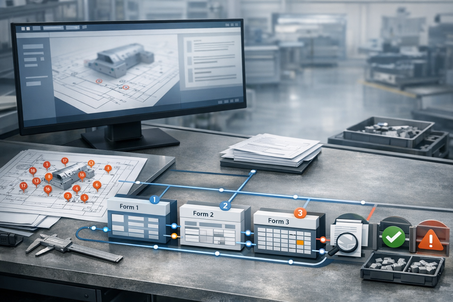
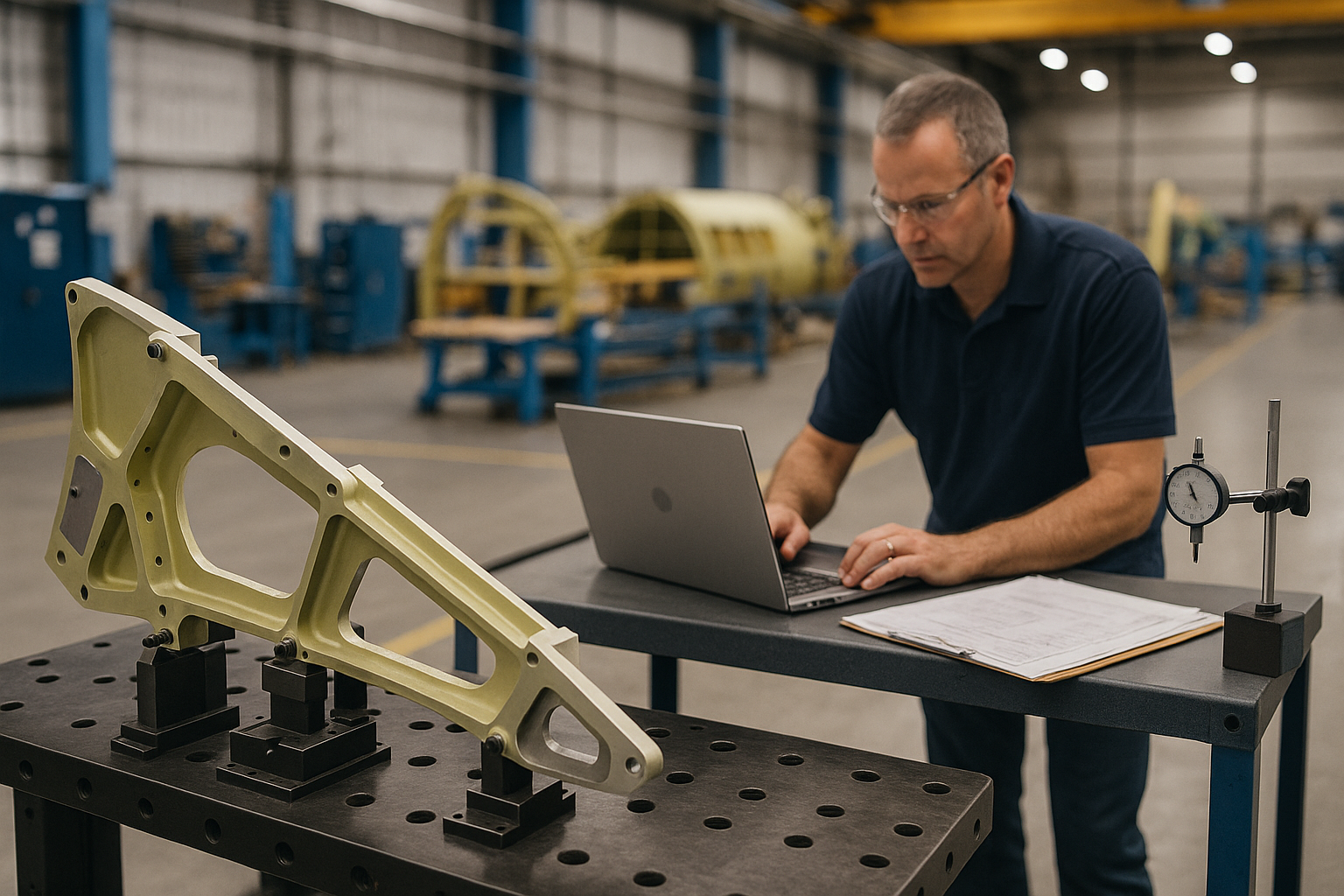
    For most aerospace manufacturers, the slowest and most error-prone part of AS9102 first article inspection (FAI) is not the measurements themselves. It is turning complex drawings into ballooned characteristics and then mapping every requirement into Forms 1, 2, and 3. Digital FAIR forms and automated ballooned drawings target this exact bottleneck, replacing hand-marked prints and Excel templates with a structured, reviewable, and reusable data model.

    This article explains how modern tools automate ballooned drawings, populate AS9102 forms, and maintain one-to-one traceability between every drawing requirement and every Form 3 line. It also shows how digital FAIRs support partial and delta FAI, integrate measurement data, and create a foundation for long-term traceability.

    For teams putting this topic into daily operation, Connect 981’s aerospace execution solutions, real aerospace execution examples, digital AS9102 FAI help connect the concept to traceability, work-order reality, and audit-ready evidence.

    For teams putting this topic into daily operation, digital AS9102 FAI, a connected execution platform help connect the concept to traceability, work-order reality, and audit-ready evidence.

    The same operating model also depends on Connect 981’s aerospace operations guidance, practical aerospace operations FAQs, especially when decisions have to move across quality, production, suppliers, and program leadership without losing context.

    If you need a broader overview of how these capabilities fit into a full platform, see our AS9102 software overview.

    Why Ballooned Drawings and FAIR Forms Are Central to AS9102

    AS9102 revolves around a simple idea: every requirement in the design must be clearly identified, measured, and documented. Ballooned drawings and FAIR forms are how that happens in practice.

    The role of ballooned drawings in capturing every requirement

    A ballooned drawing is a drawing where every verifiable requirement is given a unique identifier (a “balloon” number). This typically includes:

    • Dimensions and tolerances (linear, angular, diameters, radii, etc.)
    • GD&T callouts (position, flatness, perpendicularity, profile, and others)
    • Surface finish requirements
    • Drawing notes that imply verification (e.g., “NO SHARP EDGES”, “DEBURR ALL EDGES”)
    • Material specifications and heat-treat conditions
    • Coatings and other special processes that must be verified

    Each balloon creates a discrete, traceable “characteristic” that should appear on Form 3. When ballooning is incomplete or inconsistent, characteristic accountability breaks down and AS9102 expectations are not met.

    How Forms 1, 2, and 3 relate to the drawing

    AS9102 Rev C structures the FAIR into three core forms:

    • Form 1 – Part Number Accountability: Identifies the part, configuration, and whether the FAIR is full, partial, or delta.
    • Form 2 – Product Accountability: Lists materials, special processes, and functional tests with traceable documentation.
    • Form 3 – Characteristic Accountability: Maps every ballooned characteristic to measured or verified results and compatibility evaluations.

    The ballooned drawing drives Form 3. Each balloon ID should correspond to exactly one Form 3 line, which then references the same part and revision context defined in Form 1 and the associated materials and processes summarized in Form 2.

    Common failure modes in manual FAIR creation

    Manual FAI processes typically involve printing drawings, marking balloons with a pen, and populating Excel-based forms. This approach is familiar but fragile. Common problems include:

    • Missed or duplicated balloons: Critical dimensions can be skipped entirely or numbered twice, resulting in gaps or conflicts in Form 3.
    • Mismatch between drawing and forms: Balloon numbering on paper does not match line numbering in Excel, making reviews and audits difficult.
    • Incorrect tolerance or unit interpretation: Values are re-typed manually, increasing the chance of misreading, rounding, or unit mix-ups.
    • Weak revision control: FAIRs are completed against one drawing revision while a newer revision is already in effect, but there is no systematic link.
    • Heavy reliance on tribal knowledge: Only a few experts know how to balloon in the “right way” or which Excel template applies to which customer.

    Digital FAIR tools focus on eliminating these failure modes by treating ballooning and forms as connected, governed data rather than as disconnected documents.

    How Digital Tools Automate Ballooned Drawings

    Digital ballooning is the starting point for any modern AS9102 workflow. Instead of manually adding balloons on paper, engineers work with digital drawings and software that recognizes and structures characteristics.

    Importing PDF and CAD-derived drawings

    Most FAI scenarios still rely on 2D drawings, even when the design originates from a 3D CAD model. Effective digital ballooning starts with robust import:

    • PDF drawing import: The system ingests released PDF drawings directly from PLM or document control, preserving scaling and clarity.
    • CAD-derived drawings: For organizations using model-based workflows, tools may import 2D drawings generated from the 3D model or access published views that carry product manufacturing information (PMI).
    • Config-controlled access: The ballooning tool should clearly display the drawing revision and ensure the FAIR is always linked to the correct configuration.

    By anchoring ballooning to controlled source files, the risk of using outdated prints is dramatically reduced.

    Automated detection of dimensions, GD&T, and notes

    Once drawings are imported, modern tools use OCR and pattern recognition to identify potential characteristics:

    • Dimension values and tolerances are recognized and tagged as measurement-required characteristics.
    • GD&T frames are captured as separate, structured items with their respective datum references.
    • Notes that imply verification — such as specific finishing, cleanliness, or edge conditions — can be flagged for inclusion.

    Engineers can then review a first-pass extraction rather than ballooning everything from scratch. It is important to view this as assisted extraction, not guaranteed perfection: the software accelerates identification, but quality engineers still verify and adjust the characteristic set before release.

    Managing multi-sheet aerospace drawings and numbering

    Aerospace parts frequently require multi-sheet drawings with multiple views, detail callouts, and separate notes pages. Digital tools must handle this complexity while preserving clarity:

    • Consistent numbering across sheets: Balloon numbers remain unique across all sheets, even when a characteristic is referenced on multiple views.
    • Clear sheet and view references: Each characteristic record includes sheet number, view, and zone (if used) to make later reviews straightforward.
    • Filters for visibility: Users can filter characteristics by sheet, view, or type (dimension, note, GD&T) to simplify large FAIs.

    The outcome is a digital ballooned package where every requirement is visible, numbered, and traceable without the clutter and ambiguity of paper markups.

    Designing Effective Digital FAIR Forms

    Ballooned drawings create the characteristic structure. Digital FAIR forms turn that structure into an AS9102-compliant report that can be submitted, revised, and audited.

    Structuring Forms 1, 2, and 3 for AS9102 Rev C

    Digital FAIR tools should mirror the intent and fields of AS9102 Rev C while still being flexible enough to support customer-specific needs. Good practice includes:

    • Form 1: Controlled fields for part/assembly number, name, revision, FAIR type (full, partial, delta), and reference documents.
    • Form 2: Structured rows for materials, special processes, and functional tests, with clear linkage to certificates, NADCAP scopes, or lab reports.
    • Form 3: One row per characteristic with reference to drawing location, requirement, measured result, units, tolerance, and acceptance status.

    The software should treat these as data-backed forms rather than static templates, enabling calculated fields, consistent formatting, and robust reporting.

    Validation rules that prevent missing or inconsistent data

    One of the central advantages of digital FAIRs over spreadsheets is the ability to enforce rules that catch issues before submission. Examples include:

    • Mandatory completion of key Form 1 fields (part number, revision, FAIR type, FAI status).
    • Automatic warnings if a ballooned characteristic does not have a corresponding Form 3 entry.
    • Checks for unit consistency (e.g., preventing inches and millimeters from being mixed for the same characteristic without explicit conversion).
    • Flags when measurement results appear outside the declared tolerance range, prompting review.

    Instead of discovering issues during customer review, engineers see them while the FAIR is still in preparation.

    Prime-specific formats vs a unified data model

    Many aerospace suppliers must support different AS9102 formats or overlays requested by primes such as Boeing or Airbus. Manually maintaining separate Excel templates quickly becomes unmanageable. Digital FAIR tools should:

    • Maintain a single underlying data model that captures all required AS9102 fields.
    • Allow configurable output layouts — for example, one export tailored to a specific customer’s format and another using a standard AS9102 Rev C layout.
    • Ensure that regardless of the output style, the same governed data set underpins every FAIR.

    This approach avoids having multiple “sources of truth” while still meeting customer-specific presentation requirements.

    Ensuring One-to-One Characteristic Accountability

    Characteristic accountability is the core of AS9102: for each requirement, there is a clear, auditable link from drawing to measured result. Digital tooling makes this explicit and enforceable.

    Mapping each balloon to a unique Form 3 row

    In a well-designed system, the characteristic list created during ballooning is the same list used to populate Form 3. Key behaviors include:

    • Each balloon ID is represented once and only once on Form 3.
    • Characteristics cannot be deleted from Form 3 without equivalent change in the ballooned set, maintaining alignment.
    • Renumbering or re-grouping balloons (for example, after engineering review) automatically updates the associated Form 3 lines.

    This eliminates the common manual error of mismatched numbering between drawings and forms.

    Flagging key and critical characteristics in the data model

    Key characteristics (KCs) and critical characteristics (CCs) drive additional scrutiny and may require enhanced sampling or control plans. Digital FAIRs should support:

    • Flags on each characteristic indicating whether it is a KC, CC, or other special category as defined by the prime or internal procedures.
    • Rules that require additional documentation (e.g., process capability studies) or approvals before a FAIR with CCs can be fully released.
    • The ability to report and trend KCs and CCs across multiple FAIRs, lots, or suppliers.

    When these flags live in a structured data model instead of free-text notes, quality teams can reliably filter, monitor, and report on safety-critical items.

    Bidirectional navigation between drawing and form

    One of the most tangible usability benefits of digital FAIRs is the ability to navigate between the ballooned drawing and Form 3:

    • Clicking on a Form 3 row highlights the associated balloon on the drawing and brings it into view.
    • Selecting a balloon on the drawing jumps directly to the corresponding Form 3 line.
    • Filters and search on either side stay in sync, making internal reviews and customer discussions much faster.

    This bidirectional link reduces ambiguity and helps reviewers focus on the real question: whether the product meets requirements, not whether the documentation can be interpreted.

    Integrating Measurement Data into Digital FAIRs

    Once the characteristic structure is in place, the next challenge is getting accurate measurement and verification data into Form 3 efficiently and correctly.

    Capturing manual measurements accurately

    Many FAIs still involve manual measurements taken with calipers, micrometers, height gages, or simple gauges. Digital FAIR tools should support:

    • Guided data entry forms that show the requirement, nominal, and tolerance alongside an input field for the actual result.
    • On-the-spot validation to catch obvious mis-keys (e.g., a value an order of magnitude off expected nominal).
    • Direct association of who measured, when, and with which instrument, if required by internal or customer procedures.

    The goal is to eliminate re-keying from handwritten sheets into Excel and instead have measurement data recorded once, in the system of record.

    Importing CMM and other automated inspection data

    For complex components, automated inspection systems (CMMs, vision systems, laser scanners) often generate result files in standardized formats. A mature digital FAIR workflow:

    • Maps result file feature IDs to Form 3 characteristic IDs, ensuring that data flows to the correct line.
    • Handles multiple runs or samples, summarizing results as required by the AS9102 form while retaining detailed data behind the scenes.
    • Allows selective review, so engineers can quickly focus on out-of-tolerance or near-limit conditions.

    This tight linkage between inspection systems and FAIRs removes transcription errors and accelerates report completion.

    Handling units, tolerances, and compatibility evaluations

    AS9102 Form 3 requires more than just recording numbers. It also demands a clear compatibility evaluation that confirms whether the characteristic is acceptable. Digital FAIR tools help by:

    • Standardizing units and enforcing conversions where needed, so a drawing in inches and a CMM report in millimeters remain consistent.
    • Structuring tolerance formats (e.g., bilateral, unilateral, limit) so calculations can be automated and consistently interpreted.
    • Providing explicit fields where engineers record compatibility or attach supporting notes for borderline cases.

    Instead of interpreting free-text comments during an audit, reviewers see structured results together with a clear pass/fail or compatible/not compatible conclusion.

    Reuse and Change Management with Digital FAIR Structures

    AS9102 Rev C recognizes that not every event requires a completely new, full FAIR. Digital FAIR structures make it practical to reuse characteristic sets and manage partial or delta FAI without losing traceability.

    Reusing balloon and characteristic structures across builds

    Once a part number has been fully ballooned and its characteristics validated, that structure becomes a reusable asset:

    • New FAIRs for repeat builds can leverage the same ballooning, avoiding repeated engineering effort.
    • Suppliers or additional plants can inherit an approved characteristic set, reducing variation in interpretation.
    • Updates to the drawing trigger incremental reviews instead of new ballooning from scratch.

    This reuse is only safe if revision control is handled carefully, which is where digital tooling excels compared to file-based workflows.

    Supporting partial and delta FAI without recreating forms

    Partial and delta FAIs are often the most confusing for teams using spreadsheets. Digital FAIR tools can make them routine by:

    • Allowing Form 1 to explicitly flag FAIR type (full, partial, delta) as required by AS9102 Rev C.
    • Duplicating the baseline FAIR structure and then highlighting only those characteristics that must be re-verified.
    • Maintaining a link back to the original FAIR so reviewers see the complete history at a glance.

    Instead of building a new spreadsheet for every change, teams extend a controlled data set and capture exactly what has changed and why.

    Maintaining traceability across revisions and submissions

    Traceability in digital FAI spans more than just drawing revisions:

    • Each FAIR is linked to the drawing revision, associated change notices, and the specific production lot or serial numbers inspected.
    • Subsequent FAIRs (for example, after a process move or design modification) explicitly reference the earlier baseline FAIR.
    • Systems can provide a “family tree” of FAIRs showing how the part has evolved and when verification was repeated.

    This level of traceability is extremely difficult to maintain using independent Excel files stored on shared drives. Digital FAIR tools make it a natural byproduct of everyday work.

    How Digital FAIRs Fit into a Broader AS9102 Software Strategy

    Digital FAIR forms and ballooned drawings are the engine of AS9102 documentation, but they rarely live in isolation. When they are integrated into a broader AS9102 software approach, organizations gain:

    • Automatic population of part, revision, and purchase order data from ERP or PLM.
    • Alignment of FAIRs with shop-floor execution, work instructions, and quality checks.
    • Centralized storage and search for all FAIRs, measurement results, and supporting documents.

    To understand how these elements span planning, execution, and audit readiness, it is useful to step back and review an AS9102 software overview that covers workflow orchestration, integration, and analytics on top of the digital FAIR foundation.

    Practical Steps to Implement Digital FAIR Forms and Ballooned Drawings

    Organizations moving from manual to digital FAI can take a phased approach focused on risk reduction and quick wins.

    1. Start with high-impact parts: Select parts with complex drawings, high characteristic counts, or a history of FAIR rework.
    2. Digitize ballooning: Implement automated ballooning for those parts, validating extraction rules and review practices.
    3. Standardize AS9102 forms: Configure Forms 1, 2, and 3 templates aligned with Rev C and major customer overlays.
    4. Integrate measurement data: Pilot CMM and manual data capture flows for a subset of characteristics.
    5. Introduce partial/delta FAI logic: Once the baseline FAIR is stable, use the same structure to manage engineering changes.

    By proving value on a manageable scope first, teams build confidence and templates that can scale across programs, sites, and suppliers.

    Conclusion

    Digital FAIR forms and automated ballooned drawings transform AS9102 FAI from a manual document-creation activity into a governed, reusable data process. By automating characteristic extraction, enforcing one-to-one mapping between balloons and Form 3, and integrating measurement data, quality and manufacturing teams can reduce cycle time, lower error rates, and strengthen traceability.

    When these capabilities are connected to broader AS9102 software workflows, they become a foundation for aerospace compliance, audit readiness, and continuous improvement. The practical next step is to identify where manual ballooning and spreadsheet-based FAIRs are causing the most pain, and then pilot a digital FAIR approach that directly addresses those bottlenecks.

  • Partial vs Delta FAI in AS9102 Software: Practical Digital Strategies

    Partial vs Delta FAI in AS9102 Software: Practical Digital Strategies

    Under AS9102 Rev C, you no longer have to choose between re-doing an entire first article inspection or risking gaps in coverage when designs or processes change. Partial and delta FAI give aerospace manufacturers a structured way to verify only what has actually changed—provided you can manage the details correctly.

    This article explains how full, partial, and delta FAI relate to each other, where organizations struggle when managing them manually, and how modern AS9102 software can automate reuse, lineage, and impact analysis. The perspective here reflects common industry practice, not a legal interpretation of the standard, and final scope decisions must always follow customer and regulatory requirements.

    For teams putting this topic into daily operation, digital AS9102 FAI help connect the concept to traceability, work-order reality, and audit-ready evidence.

    For teams putting this topic into daily operation, digital AS9102 FAI, a connected execution platform, Connect 981’s aerospace execution solutions help connect the concept to traceability, work-order reality, and audit-ready evidence.

    The same operating model also depends on real aerospace execution examples, Connect 981’s aerospace operations guidance, practical aerospace operations FAQs, especially when decisions have to move across quality, production, suppliers, and program leadership without losing context.

    If you need a broader overview of digital AS9102 and FAIR workflows before diving into change scenarios, see our guide on AS9102 and digital FAI fundamentals.

    Definitions: Full, Partial, and Delta FAI Under AS9102 Rev C

    AS9102 Rev C clarifies terminology so suppliers and customers can distinguish between a brand-new verification and targeted re-verification when things change.

    When a full FAI is mandatory

    In practice, organizations treat a full FAI as the baseline reference FAIR for a given part configuration. Typical triggers include:

    • New part introduction – First production run of a new part number for a site or supplier.
    • Major design changes impacting form, fit, or function – For example, a new rib structure on a wing component or a significant geometry change on a turbine blade.
    • New manufacturing source – Moving production to a different supplier or facility when the customer requires full re-validation.
    • Extended production lapse – When no parts have been produced for an extended period (often around two years, but this can be customer-specific).

    Under a full FAI, every characteristic on the drawing and applicable specifications must be ballooned and accounted for on Form 3, with supporting material and process evidence on Forms 1 and 2.

    Typical triggers for partial FAI

    Partial FAI is used when only selected characteristics require re-verification, usually because the manufacturing process has changed while the design itself has not. Common triggers include:

    • Process or operation changes – A drilling or milling operation is moved to a different machine, cell, or facility.
    • Tooling or fixture changes – New cutting tools, workholding, or gaging that could affect particular dimensions.
    • Supplier or sub-tier changes for specific operations – For example, moving a plating step to a new special process supplier while the base part remains unchanged.
    • Documented process issues – A corrective action drives re-validation of a specific subset of characteristics.

    The scope of a partial FAI is defined by which characteristics are affected by the process change. You still rely on the existing baseline FAIR for unchanged items.

    Typical triggers for delta FAI

    Delta FAI applies when there is a design or specification change, and you must verify only the impacted characteristics against the new configuration while referencing the prior full FAI.

    • Drawing revision changes – A revision adds, removes, or modifies dimensions, tolerances, GD&T callouts, or notes.
    • Specification updates – A new material spec is called out, a test requirement changes, or a surface treatment is updated.
    • Additional features – New holes, cutouts, stiffeners, or bosses are added to an existing part.
    • Tolerance changes – A previously generous tolerance is tightened on high-risk features.

    The delta FAIR documents only changed and newly added characteristics, but it must clearly reference the baseline FAIR for everything else. This is where digital lineage and linking are especially valuable.

    Common Challenges with Manual Partial and Delta FAI

    On paper and spreadsheets, partial and delta FAI often create more confusion than efficiency. The standard allows targeted verification, but without structured tools, teams struggle to manage scope correctly.

    Over-documentation and unnecessary re-inspection

    To be “safe,” some organizations treat every change as a reason to redo a near-full FAI:

    • Re-ballooning entire drawings instead of only the affected areas.
    • Copy-pasting a prior Form 3 and re-entering measurements for most characteristics.
    • Running duplicate inspections on features that are demonstrably unaffected by the change.

    This wastes engineering capacity, clogs CMM queues, and delays deliveries. It also undermines the original purpose of partial and delta FAI: focusing effort where risk actually changed.

    Under-documentation and missed linked features

    The opposite problem is just as common: teams underestimate scope.

    • A tooling change that affects multiple related features is treated as affecting only one dimension.
    • A GD&T callout is revised, but only one characteristic is updated instead of the entire feature pattern.
    • Downstream processes or mating parts impacted by a tolerance change are not considered.

    Without structured impact analysis, it is easy to miss derived or associated characteristics, exposing you to customer rejections or findings during AS9102 or AS9100 audits.

    Traceability gaps between baseline and follow-on FAIRs

    Manual systems often handle follow-on FAIRs as isolated files:

    • Baseline and delta FAIRs live in different network folders with inconsistent naming.
    • Form 1 status (full, partial, delta) is not used consistently, so reviewers cannot tell what they are looking at.
    • There is no simple way to see how many FAIRs exist for a part and what changed each time.

    These gaps make it hard to prove configuration history and FAIR lineage when customers or auditors ask for evidence.

    Designing Software Workflows for Partial FAI

    Modern AS9102 software can codify partial FAI logic so engineers execute consistent, risk-based scopes instead of reinventing the process each time.

    Tagging FAIRs with status (full, partial, delta)

    Start with explicit status tagging:

    • Every FAIR record uses the Form 1 field to mark full, partial, or delta.
    • Workflows and dashboards filter and report based on that status.
    • Search tools allow users to quickly find the most recent full FAI for a part and all associated partial or delta FAIRs.

    In a software system, status tagging can also drive automated routing and required approvals—for example, forcing quality or customer approval when a partial FAI is used to qualify a new facility.

    Reusing baseline characteristic data safely

    The biggest efficiency gain from digital FAI comes from treating the baseline FAIR as a structured data set rather than a static PDF.

    • Characteristics extracted and ballooned once are stored as reusable digital objects.
    • When a partial FAI is created, the software clones the baseline FAIR metadata, but flags only selected characteristics as “in scope” for re-verification.
    • Unchanged characteristics remain present for context but carry a clear indication that they are not being re-inspected as part of this partial FAI.

    This approach preserves one source of truth for the part while avoiding duplicated Form 3 lines and repeated manual entry.

    Controlling scope when process changes occur

    Well-designed workflows guide engineers through scope decisions instead of leaving everything to memory:

    • Partial FAI templates prompt users to identify the operation, machine, or facility that changed.
    • Characteristics in the baseline FAIR are linked to process steps and work centers.
    • The system proposes a list of characteristics likely affected by the changed operation.

    Engineers can then review, expand, or narrow that list, but they are no longer starting from a blank spreadsheet. This reduces the chance of missing characteristics that should logically be within partial FAI scope.

    Managing Delta FAI for Engineering Changes

    Delta FAI sits at the intersection of engineering change control and production verification. Software can bridge PLM, drawings, and FAIRs so the right characteristics are re-verified every time a revision is released.

    Linking ECNs and drawing revisions to affected balloons

    An effective digital workflow starts with change artifacts—Engineering Change Notices (ECNs), Engineering Change Orders (ECOs), or PLM change objects.

    • Each ECN or drawing revision is associated with the relevant part numbers in the FAI system.
    • The system compares old and new drawings, highlighting changed callouts, dimensions, notes, or specifications.
    • These differences are mapped directly to balloon numbers on the digital drawing and their corresponding Form 3 rows.

    With this linkage in place, the delta FAIR can be generated from a concrete list of changed characteristics instead of relying on manual visual comparison.

    Impact analysis to identify which characteristics must be re-verified

    The next layer of capability is impact analysis—looking beyond the explicitly edited dimension to understand what else should be considered in scope.

    • A tighter positional tolerance on a hole pattern may also bring associated datum features, countersinks, or threads into scope.
    • A surface finish requirement might impact both the machining operation and subsequent coating steps.
    • Changes to a material specification could trigger new or repeated material tests and special process verifications.

    Software can use rules and relationships embedded in the data model to suggest affected characteristic groups. Engineers then review and finalize the scope rather than building it from scratch.

    Building FAIR family trees and lineage views

    Over the life of a part, you may have one full FAI plus multiple partial and delta FAIRs. Without tools, keeping track of this family is difficult.

    • Digital systems construct a FAIR family tree that shows the baseline full FAI and every associated partial or delta FAIR, in chronological order.
    • Each child FAIR contains explicit links back to its parent FAIR and drawing revision.
    • Users can click into a characteristic and see a history of all times it was re-verified and why.

    This lineage not only supports audits; it also helps engineers quickly understand what has already been proven when planning further changes.

    Examples: Partial and Delta FAI Scenarios in Aerospace

    Concrete scenarios help clarify when to consider partial versus delta FAI and how software can handle each case. The exact decision in your organization should always follow customer and internal requirements, but these patterns are common.

    Machine or facility relocation of a machining operation

    Scenario: A supplier moves a 5-axis machining operation for a structural bracket from Plant A to Plant B. The drawing and spec do not change.

    • FAI type: Typically a partial FAI focused on characteristics produced by the relocated operation.
    • Manual challenge: Determining which dimensions are affected by the moved operation and which remain untouched.
    • Software approach: Link each characteristic in the baseline FAIR to its operation routing. When the routing changes, the system suggests the affected characteristics and generates a partial FAIR pre-populated with those characteristics only.

    Tolerance changes on critical hole patterns

    Scenario: Engineering tightens the positional tolerance and surface finish requirement on a critical hole pattern in a landing gear component.

    • FAI type: A delta FAI covering the modified pattern and any associated datums or related features deemed impacted.
    • Manual challenge: Ensuring all holes in the pattern, and not just one edited dimension, are included in the delta scope.
    • Software approach: The system compares drawing revisions, identifies the updated tolerance and finish, and maps those edits to all ballooned features in the pattern. Engineers validate the automatically generated list for the delta FAIR.

    Material substitution for specific callouts

    Scenario: A casting alloy spec is updated, or a substitute material is permitted for specific callouts on a structural part.

    • FAI type: Often a delta FAI covering characteristics and tests influenced by the new material, plus a new record of material certifications on Form 2.
    • Manual challenge: Understanding which tests or special processes need to be repeated and which geometric characteristics need closer scrutiny.
    • Software approach: Characteristics and Form 2 entries linked to the original material spec are flagged; the system prompts for updated certs, test results, and any newly required verifications.

    Measuring the Impact of Digital Partial and Delta FAI

    Organizations often adopt digital FAI tools to solve immediate pain, but you should also measure the impact of better handling of partial and delta FAI over time.

    Cycle time reductions and engineering capacity gains

    Key metrics for partial and delta FAI include:

    • Average time to complete a full FAI vs. partial/delta – With robust reuse and impact analysis, delta FAIRs should routinely take 50–80% less time than a full FAI.
    • Number of FAIRs completed per quality engineer – Automation should increase throughput without extending work hours.
    • Queue time at CMM and inspection resources – Reduced scope directly shortens queues when only affected characteristics are re-measured.

    Effect on audit findings and customer rejections

    Digitizing partial and delta FAI should also improve compliance outcomes:

    • Fewer documentation-related FAIR rejections – Clear status tagging and lineage reduce confusion about what has been verified when.
    • Reduced AS9100/AS9102 audit findings related to configuration control and traceability.
    • Better responsiveness in customer reviews – FAIR family trees and instant retrieval of supporting evidence shorten review cycles.

    Best practices for standardizing partial/delta policies

    To get consistent value from your software, codify your decision logic:

    • Create a partial vs. delta decision matrix aligned with the AS9102 standard and major customer requirements.
    • Embed that matrix into workflow rules and templates so engineers see guidance in context.
    • Review edge cases regularly and adjust rules to reflect lessons learned from audits and customer feedback.

    Over time, your partial and delta FAI process becomes repeatable, auditable, and scalable across sites and suppliers rather than dependent on a few experts.

    Using Partial and Delta FAI as a Strategic Lever

    Done well, partial and delta FAI strategies turn engineering change from a recurring scramble into a controlled, data-driven process. Modern AS9102 software helps you:

    • Reuse baseline FAIR data with confidence instead of rebuilding every time.
    • Focus verification on clearly defined, risk-based scopes.
    • Maintain transparent lineage across full, partial, and delta FAIRs for each part number.
    • Demonstrate robust configuration control during customer and certification audits.

    As your organization advances its digital FAI capabilities, consider how partial and delta FAI workflows align with broader goals like standardizing processes across plants, integrating with PLM and MES, and supporting a connected aerospace operations platform.

    For a deeper foundation on digital FAI tools, templates, and integrations, review the cluster hub on AS9102 and digital FAI fundamentals and then map your current partial and delta FAI workflows against the capabilities described there.

  • Integrating AS9102 Software with ERP, MES, PLM, and QMS in Aerospace

    Integrating AS9102 Software with ERP, MES, PLM, and QMS in Aerospace

    Integrating AS9102 Software with ERP, MES, PLM, and QMS in Aerospace

    In modern aerospace manufacturing, AS9102 first article inspection (FAI) cannot be treated as a stand-alone activity. To keep programs on schedule and pass audits reliably, your FAI process and first article inspection reports (FAIRs) must be tightly connected to ERP, MES, PLM, and QMS systems. True AS9102 software integration removes manual data re-entry, strengthens configuration control, and makes FAIRs part of the broader digital thread.

    This article explains how AS9102 tools should integrate with core enterprise systems, the typical data flows you should expect, and example workflows that embed FAI into day-to-day production. It is a spoke in a larger guide on AS9102 software and a unified aerospace operations platform.

    For teams putting this topic into daily operation, digital AS9102 FAI, shop floor execution control, ERP, MES, and PLM integration paths help connect the concept to traceability, work-order reality, and audit-ready evidence.

    The same operating model also depends on a connected execution platform, Connect 981’s aerospace execution solutions, real aerospace execution examples, Connect 981’s aerospace operations guidance, especially when decisions have to move across quality, production, suppliers, and program leadership without losing context.

    Why AS9102 FAI Cannot Live in a Silo

    The risks of stand-alone spreadsheets and local tools

    Many aerospace OEMs and suppliers still run FAI using Excel templates, local ballooning tools, and network drive folders. Even when these tools generate AS9102-compliant forms, they usually sit outside the enterprise stack. The result is a set of disconnected artifacts that must be reconciled manually with ERP, MES, PLM, and QMS data.

    Common risks of siloed FAI tools include:

    • Re-keying errors: Part numbers, revisions, purchase orders, and lot data are typed multiple times across systems.
    • Configuration mismatches: FAIRs are created to one drawing revision while ERP or PLM have already advanced to another.
    • Limited reuse: Data from one FAI event cannot easily be reused for partial or delta FAI, change management, or trend analysis.
    • Local workarounds: Each plant or engineer maintains their own templates and conventions, undermining standardization.

    How disconnected FAI impacts schedule, quality, and audits

    When FAI is disconnected from core systems, the impact shows up quickly on programs and audits:

    • Schedule delays: FAIRs are started late because nobody realizes a new part or major change has reached production until after work orders are released.
    • Rejections and rework: Customers reject FAIRs due to wrong part numbers, incorrect revision levels, or missing traceability back to material and special processes.
    • Audit exposure: During AS9100 or customer audits, teams scramble across email, shared drives, and local PCs to reconstruct the full FAI picture.
    • Lost lessons learned: Nonconformances identified during FAI do not feed back into design or process improvement because they are trapped in separate spreadsheets or PDFs.

    Benefits of connected FAI data across the value stream

    By contrast, integrating AS9102 software into your enterprise architecture produces tangible benefits:

    • Single source of truth: Part, revision, and order data flow directly from ERP and PLM into FAIRs, eliminating conflicting records.
    • Automatic triggering: New part introductions, engineering changes, or process transfers can automatically trigger FAI requirements.
    • Closed-loop quality: FAIRs connect to nonconformance reports (NCRs), corrective actions (CAPAs), and process controls in the QMS.
    • Digital thread: FAI becomes a key node linking design, planning, production, quality, and in-service data.

    Key Integration Points for AS9102 Software

    Effective AS9102 software touches multiple systems. The integrations do not need to be implemented all at once, but the data model should anticipate each of these connections.

    ERP: part numbers, revisions, orders, and routings

    The ERP system is typically your commercial and planning source of truth. AS9102 software should at minimum:

    • Import item master data: Part numbers, descriptions, and key attributes such as make/buy status or commodity type.
    • Sync revisions: Current engineering or manufacturing revision, ideally cross-referenced to PLM identifiers.
    • Link to orders: Work orders, purchase orders, and sales orders that require FAIR submission.
    • Reference routings: Major operations or work centers associated with the part, enabling routing-based FAI rules.

    Typical workflows include:

    • FAI software periodically receives new or updated item data from ERP so Form 1 can be populated reliably.
    • When an order meets FAI criteria (e.g., first production lot, new part, or re-start after a lapse), ERP flags it, and an FAI record is automatically created.

    MES: work orders, operations, machines, and operators

    MES or shopfloor systems hold execution context. Integrating AS9102 software with MES enables:

    • Work order linkage: FAIRs tied to specific work orders or lots.
    • Operation-level traceability: Measurement results mapped to the operation, machine, and operator that produced the feature.
    • In-process data reuse: Dimensional or process checks collected during production can automatically populate Form 3.

    Common patterns include:

    • Launching FAI-specific inspection plans or electronic checklists when an FAI-designated work order reaches certain operations.
    • Pulling measurement data from automated equipment or operator tablets directly into the FAIR database.

    PLM: drawings, models, and engineering change data

    PLM or PDM systems manage design authority. They are essential for ensuring that FAIRs reflect the correct design configuration:

    • Drawing and model access: AS9102 software imports the released PDF drawings or model-based definition (MBD) for ballooning.
    • Revision control: FAIRs are tagged to specific design revisions; when a change is released, impacted characteristics are identified for delta FAI.
    • Change notice linkage: Engineering change orders (ECOs) or equivalent are associated with affected FAIRs for traceability.

    In a mature setup, PLM becomes the source of balloonable artifacts, while the FAI system manages characteristic extraction, accountability, and measurement results.

    Data Flows Between FAI and Quality Systems

    Beyond ERP, MES, and PLM, AS9102 workflows must connect to the organization’s QMS to support AS9100 and customer requirements.

    Connecting FAIRs to nonconformance and corrective actions

    FAI is often where early nonconformances are discovered. Integration with the QMS should support:

    • Linked NCRs: Each out-of-tolerance characteristic on Form 3 can initiate or link to an NCR.
    • Corrective action traceability: CAPAs reference the exact part, revision, and FAIR where the problem was found.
    • Closed-loop verification: Follow-up FAIRs or delta FAI events demonstrate that corrective actions were effective.

    Reusing FAI data in AS9100 documentation

    The structured data created during FAI can power broader quality documentation:

    • Evidence for process validation and production approval under AS9100.
    • Inputs to risk management and FMEA, particularly for key characteristics that show high variation.
    • Support for control plan updates and sampling strategy adjustments informed by FAI results.

    Without integration, teams must copy data from FAIRs into separate QMS records. With integration, FAI becomes a structured data source that feeds other processes automatically.

    Aligning calibration and measurement system data

    For FAIRs to stand up during audits, measurement results must tie back to calibrated instruments and qualified gages. Integration between AS9102 software and calibration/asset management systems should allow:

    • Recording which gage or CMM program was used for each measurement.
    • Verifying that instruments were within calibration at the time of use.
    • Flagging FAIRs if a later calibration failure suggests results may be suspect.

    This alignment simplifies responses when auditors ask for “evidence that gages used during this FAI were calibrated.”

    Example End-to-End AS9102 Workflow with Integrations

    To illustrate how these integrations work in practice, consider an end-to-end workflow for a new aerospace part.

    Triggering FAI from new work orders or part introductions

    1. Design release in PLM: Engineering releases a new part and associated drawing or model. PLM notifies downstream systems.
    2. ERP item creation: The part is added or updated in ERP, including revision and primary routing. A rule marks this part as requiring FAI for the first production lot.
    3. Automatic FAI record creation: When the first qualifying work order is created in ERP or MES, the AS9102 system automatically creates a corresponding FAIR record and Form 1 header using imported part/order data.

    Collecting inspection data on the shopfloor

    1. Ballooning and planning: The quality or manufacturing engineer imports the released drawing or model into the AS9102 tool, auto-balloons characteristics, and defines which operations or work centers will generate which measurements.
    2. Shopfloor execution: Operators or inspectors receive digital checklists or inspection plans via MES-integrated terminals or tablets. As they record measurements, results flow back to the FAI database, filling Form 3 rows linked to balloon numbers.
    3. Nonconformance handling: Any out-of-tolerance result automatically opens an NCR in the QMS, with a reference to the specific characteristic and FAIR.

    Approving and submitting FAIRs with linked evidence

    1. Quality review: Quality engineers review Form 1–3 inside the AS9102 system, verify that all characteristics are accounted for, and confirm that required material and special process certificates are attached.
    2. Electronic approval: FAIRs move through defined approval workflows with electronic signatures and time stamps.
    3. Submission and archiving: A customer-ready FAIR package (PDF plus structured data if required) is generated and submitted. The system stores the FAIR in a centralized repository, indexed by part, revision, order, and supplier.
    4. Future reuse: When a design or process changes, the baseline FAIR is reused to create partial or delta FAIRs rather than starting from scratch.

    Multi-Site and Supplier Integration Considerations

    Most aerospace programs involve multiple plants and a complex supplier network. AS9102 integration must account for this distributed reality.

    Standardizing FAIR templates across sites and suppliers

    Without standardization, each site or supplier tends to customize FAIR formats and naming conventions. A connected platform enables you to:

    • Define global AS9102 templates that enforce common fields and rules.
    • Allow limited configuration for customer-specific layouts while keeping a consistent underlying data model.
    • Report across FAIRs from different locations because they share the same structure.

    Supplier portals and shared data models

    For purchased parts, suppliers often own the FAI execution, but the OEM is still responsible for overall airworthiness. A supplier-facing portal or shared AS9102 platform can:

    • Provide guided FAIR templates aligned with your standards and customer requirements.
    • Enable suppliers to upload ballooned drawings, Forms 1–3, and certifications directly into your system.
    • Support automated validation checks on incoming FAIRs before they are accepted.

    This approach reduces variation in FAIR quality and accelerates review cycles, especially for high-volume or global supplier bases.

    Managing customer-specific requirements globally

    Major primes and engine manufacturers often apply their own FAIR formats, field requirements, and submission methods. An integrated platform should handle:

    • Configuration by customer: Mapping a single internal data model to different outward-facing FAIR templates.
    • Rule-based triggers: Customer and program-specific criteria for when FAI, partial FAI, or delta FAI is required.
    • Central visibility: Dashboards showing FAI status across customers, plants, and suppliers.

    Architecture Patterns for AS9102 Integration

    There is no one-size-fits-all approach to integrating AS9102 software. The right architecture depends on your existing systems, IT strategy, and digital maturity.

    Point-to-point vs platform-centric integrations

    Two broad patterns are common:

    • Point-to-point: The FAI system connects directly to ERP, MES, PLM, and QMS with separate integrations for each. This can be fast to implement for a small footprint but may become complex to maintain as scope grows.
    • Platform-centric: AS9102 capabilities are part of a broader aerospace operations platform that already integrates with ERP/MES/PLM/QMS. FAI reuses existing data models and services.

    Organizations starting with light integrations might choose point-to-point initially and then consolidate into a platform approach as volume and complexity increase.

    APIs, data lakes, and middleware approaches

    From a technical standpoint, integrations usually rely on one or more of the following:

    • REST or SOAP APIs: Near-real-time synchronization of parts, orders, and status updates.
    • Message queues or integration buses: Event-driven flows (e.g., a new ECO triggers delta FAI creation).
    • Data lakes or warehouses: Consolidated reporting and analytics across FAIRs, production data, and nonconformances.
    • File-based exchange: CSV, XML, or JSON batches for legacy environments where APIs are limited.

    Regardless of the technical mechanism, governance is critical: clear ownership of master data, change management, and validation of integrations before they are used for production decisions.

    Roadmap planning for digital thread and future scalability

    AS9102 integration should be planned as part of a broader digital thread roadmap rather than as an isolated IT project. Key roadmap considerations include:

    • Sequencing integrations (e.g., start with ERP/PLM, then add MES and QMS).
    • Defining standard identifiers for parts, revisions, orders, and characteristics across systems.
    • Ensuring that FAI data structures can support future capabilities such as MBD, AI-assisted sampling, and advanced analytics.

    For many organizations, moving from stand-alone ballooning tools to a unified aerospace operations platform is the key step that defines long-term scalability.

    Conclusion

    Integrating AS9102 software with ERP, MES, PLM, and QMS transforms FAI from a manual compliance burden into a strategic source of configuration control and process insight. By designing data flows carefully, standardizing templates across sites and suppliers, and choosing an architecture that fits your digital thread roadmap, you can reduce FAIR cycle times, cut rework, and strengthen audit readiness.

    The most successful aerospace organizations treat FAI as a connected process embedded in everyday manufacturing workflows. Start by identifying your highest-friction handoffs—typically between design, planning, and quality—and design integrations that eliminate re-keying while preserving rigorous validation and security review.

  • AS9102 Audit Readiness: Building Digital Traceability for FAI

    AS9102 Audit Readiness: Building Digital Traceability for FAI

    AS9102 Audit Readiness: Building Digital Traceability for FAI

    For aerospace manufacturers and suppliers, AS9102 first article inspection reports (FAIRs) are among the most scrutinized records in any audit. AS9100 surveillance audits, customer process reviews, and regulatory oversight all use AS9102 data as evidence of process capability, configuration control, and traceability.

    When FAIRs are scattered across spreadsheets, email threads, and shared drives, audit preparation can consume days of engineering time and still produce gaps. By contrast, digital AS9102 workflows give you structured data, clear traceability links, and rapid retrieval of evidence that can turn a high-stress audit into a routine review.

    For teams putting this topic into daily operation, digital AS9102 FAI, part traceability and as-built evidence, a connected execution platform help connect the concept to traceability, work-order reality, and audit-ready evidence.

    The same operating model also depends on Connect 981’s aerospace execution solutions, real aerospace execution examples, Connect 981’s aerospace operations guidance, practical aerospace operations FAQs, especially when decisions have to move across quality, production, suppliers, and program leadership without losing context.

    This article explains how auditors actually use AS9102 FAIRs, what they look for in your records, and which digital traceability capabilities matter most. It builds on the broader AS9102 software: digital first article inspection for aerospace manufacturing hub by focusing specifically on audit readiness.

    How AS9102 FAIRs Are Used in Audits

    FAIRs are more than part-specific documents; they are a window into how effectively your quality management system operates. Different types of audits use AS9102 evidence in slightly different ways.

    AS9100 surveillance and certification audits

    Certification and surveillance auditors use FAIRs to confirm that your organization:

    • Plans and executes first article inspection when required (new parts, design changes, process changes, lapses in production, and other triggers defined in AS9102).
    • Maintains configuration control so FAIRs match the correct drawing and specification revisions.
    • Demonstrates traceability from design requirements to inspection results, material certifications, and special processes.
    • Controls documents and records, including templates, approvals, and revisions.

    Typically, auditors will:

    • Sample a subset of part numbers and request the associated full, partial, or delta FAIRs.
    • Trace from the FAIR to the underlying drawing, work order, and material or process records.
    • Follow the trail into related procedures, work instructions, and training records.

    Gaps here often translate directly into nonconformances against AS9100 requirements for configuration management, monitoring and measurement, and documented information.

    Customer source inspections and process audits

    Customer auditors are usually more part- and program-focused. They use FAIRs to answer questions such as:

    • Did this supplier prove the process before we accepted production parts?
    • Are key characteristics (KCs) and critical characteristics (CCs) consistently controlled?
    • Are customer-specific clauses or purchase order requirements visible in the FAIR and supporting records?

    In many cases, the FAIR becomes the primary reference when customers evaluate supplier performance, approve new sources, or investigate recurring escapes. If FAIRs are incomplete, inconsistent, or hard to retrieve, confidence in your overall system immediately drops.

    Regulatory oversight and airworthiness evidence

    Regulators and delegated organizations (for example, through Designated Engineering Representatives or similar roles) rarely review every FAIR, but they expect to see that:

    • FAI is integrated into your production system as a standard practice, not a one-off activity.
    • Traceability exists from serial- and lot-level hardware back to the FAIR and its supporting evidence.
    • Special processes, materials, and key safety characteristics are verified and documented.

    When a potential airworthiness concern emerges, FAIRs and their traceability chain become critical inputs to investigations and corrective actions.

    What Auditors Typically Look for in AS9102 Records

    While each auditor brings their own style, there is a consistent core of AS9102-related questions and checkpoints. Understanding these expectations allows you to design your digital workflows around them.

    Characteristic accountability and completeness

    Characteristic accountability is central to AS9102. Auditors want to confirm that:

    • Every applicable requirement on the drawing and specification set has been identified and ballooned.
    • Each ballooned characteristic maps to exactly one row on Form 3.
    • Results on Form 3 are complete, legible, and clearly indicate acceptance or nonconformance.
    • Key and critical characteristics are identified and handled per internal and customer procedures.

    Digital tools make this easier by:

    • Automating ballooning of dimensions, GD&T, notes, and other requirements.
    • Synchronizing balloons to Form 3 so there are no missing or duplicated characteristics.
    • Providing click-through navigation between the Form 3 row and the corresponding balloon on the drawing.

    Correct usage of Forms 1, 2, and 3

    Auditors will review how you populate and control the three primary AS9102 forms:

    • Form 1 – Part Number Accountability
      They check that the part number, revision, FAI type (full, partial, delta), and related part or assembly details are accurate and consistent with your engineering and planning systems.
    • Form 2 – Product Accountability
      Expect questions about how you capture and link materials, special processes, and functional tests. Auditors verify that each entry is backed by a material certification, special process record, lab report, or functional test evidence.
    • Form 3 – Characteristic Accountability, Verification and Compatibility Evaluation
      They confirm that measurements, test results, and compatibility checks are properly recorded, with clear acceptance status and reference to the correct drawing revision.

    Misuse of forms—such as putting material data on Form 3, omitting FAI type on Form 1, or mixing drawing revisions—often triggers findings.

    Evidence of proper approvals and document control

    AS9102 FAIRs must reflect your broader document control practices. Auditors typically ask:

    • Who prepared, reviewed, and approved each FAIR—and when?
    • How do you ensure that only the latest approved FAIR template is in use?
    • What happens when a form or template is revised? Can you still retrieve prior versions?

    Digital AS9102 systems streamline these checks by embedding electronic signatures, maintaining template versions, and recording a time-stamped audit trail of changes.

    Building End-to-End Digital Traceability

    Traceability is the connective tissue that lets auditors move from drawing to FAIR to physical hardware and supporting evidence without losing the thread. A robust digital implementation captures these links by design.

    Linking FAIRs to serials, lots, and work orders

    At a minimum, your system should allow anyone to start from a specific part and quickly find:

    • The relevant FAIR(s) for that part number and configuration.
    • The associated work orders or shop orders and their status.
    • Individual serial numbers or lot numbers covered by the FAIR.

    From an audit perspective, this enables scenarios such as:

    • Starting from a serial number in service and working backward to the FAIR.
    • Starting from a FAIR and working forward to identify which batches or serials it covers.
    • Verifying that subsequent builds reference the correct baseline, partial, or delta FAIR.

    Integrating AS9102 software with ERP or MES makes these connections much more reliable than relying on manual data entry in spreadsheets.

    Associating material certs and special process records

    Auditors frequently follow the FAIR trail into materials and processes. Effective digital traceability includes:

    • Direct links between Form 2 entries and stored material certifications (e.g., heat, lot, and mill certs).
    • Attachments or references for special process records such as heat treatment, plating, welding, or NDT, including NADCAP scope where applicable.
    • Ability to filter or search FAIRs based on specific material lots or process batches when investigating issues.

    Instead of searching network folders for a PDF with a similar name to the lot number, auditors can click from the Form 2 line item directly to the supporting cert. That level of organization and speed sends a strong signal of control.

    Capturing calibration and equipment traceability

    For measurement and test data, auditors also care about the instruments and equipment used. Strong digital traceability supports:

    • Identifying which measurement devices or gages were used for specific characteristics.
    • Linking those devices to calibration records and due dates.
    • Demonstrating that no out-of-calibration equipment was used for FAI.

    Some organizations capture gage IDs directly in Form 3 or in linked inspection records. Others maintain traceability via integrated QMS tooling. Either way, the goal is to answer, with evidence: “How do you know the measurements in this FAIR are trustworthy?”

    How AS9102 Software Simplifies Audit Preparation

    Digital AS9102 platforms are not a substitute for good processes, but they make those processes visible and repeatable. The biggest audit-readiness gains come from how software centralizes data, preserves history, and standardizes outputs.

    Centralized search and retrieval across programs and suppliers

    Instead of chasing files across email, laptops, and shared drives, a central AS9102 system allows you to:

    • Search FAIRs by part number, part family, revision, work order, serial number, supplier, or customer.
    • Filter by FAI type (full, partial, delta) and status (draft, in review, approved, rejected).
    • Retrieve all FAIRs associated with a particular program or platform in seconds.

    During an audit, this means you can respond to document requests in minutes instead of hours or days, while maintaining confidence that you have the complete and correct records.

    Audit logs and version control for FAIRs and templates

    Auditors often ask, implicitly or explicitly, “How do you know this record is accurate and has not been altered inappropriately?” Strong digital controls help you demonstrate that by design:

    • Every FAIR has a full audit trail: who created it, who edited each field, who approved it, and at what date and time.
    • Template versions are controlled, so you can show exactly which revision of the AS9102 form was used for a given FAIR.
    • Historical versions of FAIRs are preserved, not overwritten, which is especially important for delta FAIs and repeated builds.

    When an auditor questions an entry or a change, you can walk through the digital history instead of relying on memory and handwritten notes.

    Standardized exports for audit evidence packages

    Many audits require you to assemble “evidence packages” that include:

    • Completed AS9102 Forms 1, 2, and 3.
    • Ballooned drawings.
    • Material certifications, special process records, and lab reports.
    • Relevant procedures or work instructions.

    Modern AS9102 software can generate these packages in standardized formats (often PDF plus native data exports) with a few clicks. Some systems also support customer-specific layouts and naming conventions while keeping a single internal data model.

    The outcome is not just audit speed, but consistency: every auditor sees complete and similarly structured evidence, which reduces confusion and follow-up questions.

    Preventing Common FAI-Related Audit Findings

    Most AS9102-related nonconformances are predictable. Understanding the patterns allows you to design your digital workflows, training, and checks to avoid repeat issues.

    Incomplete or mismatched FAIRs

    Frequent findings include:

    • FAIRs that do not cover all characteristics on the released drawing set.
    • FAIRs referencing the wrong drawing revision or obsolete specifications.
    • Inconsistencies between the part revision on the FAIR and the ERP, PLM, or purchase order.

    Digital mitigations include:

    • Automatic drawing import and ballooning tied to a specific revision.
    • Integration with PLM or ERP to pre-populate part and revision fields.
    • Validation rules that prevent approval if required fields or attachments are missing.

    Poor change control for partial and delta FAI

    Another common source of findings is how organizations handle changes:

    • Re-performing full FAI when only a subset of characteristics changed, without clearly documenting why.
    • Performing limited measurements but failing to declare the FAIR type as partial or delta on Form 1.
    • Creating new FAIRs that do not clearly reference the baseline FAIR they build upon.

    Digital AS9102 tools reduce this risk by:

    • Explicitly tagging FAIRs as full, partial, or delta and enforcing required fields for each type.
    • Reusing baseline FAIR data and clearly identifying only those characteristics impacted by the change.
    • Maintaining family trees or lineage views showing the relationships between the original and subsequent FAIRs.

    Inconsistent use of templates across sites

    Multi-site organizations and global supply chains often struggle with inconsistent FAIR formats and processes, leading to:

    • Different spreadsheet templates with different required fields.
    • Site-specific shortcuts that omit data important to customers or regulators.
    • Confusion during audits when evidence from different plants looks and behaves differently.

    By deploying a common digital AS9102 platform, you can enforce:

    • Standard templates that still allow for controlled customer-specific variants.
    • Shared workflows for preparation, review, and approval.
    • Centralized reporting on FAIR status and issues across all sites and key suppliers.

    Using FAI Data for Continuous Improvement

    Audit readiness improves dramatically when FAIRs are not just compliance paperwork but also inputs to continuous improvement. Digital traceability turns FAI data into an analytical asset.

    Trend analysis across FAIRs for recurring issues

    With structured, centralized FAI data, you can:

    • Identify characteristics that routinely run close to tolerance limits.
    • Spot recurring nonconformances for specific features, processes, or materials.
    • Compare performance across plants or suppliers for the same part or family.

    These insights inform process capability work, supplier development, and risk-based planning for future FAIs.

    Feeding lessons learned into design and process controls

    Digital FAIRs make it easier to loop findings back into engineering and manufacturing:

    • Highlight design features that consistently cause manufacturing or inspection challenges.
    • Provide quantitative evidence for adjusting tolerances, GD&T schemes, or process parameters.
    • Support risk assessments and control plans for future parts with similar features or processes.

    When auditors ask how you use data to drive improvement—not just compliance—you can point to structured analyses of FAIR results and resulting changes in design or process documentation.

    Aligning FAI improvements with AS9100 objectives

    AS9100 emphasizes risk-based thinking, process performance, and continual improvement. Digital AS9102 implementations support these objectives by:

    • Reducing the time and cost of FAI, freeing engineering capacity for proactive work.
    • Lowering FAIR rejection and rework rates through standardized, validated workflows.
    • Providing fact-based metrics on FAI cycle times, defects, and bottlenecks.

    This alignment is attractive to auditors: they see that your investment in digital FAI is part of a broader quality strategy rather than a narrow compliance response.

    Putting It All Together: A Practical Path to AS9102 Audit Readiness

    Preparing for AS9102-focused audits is not about building a separate checklist; it is about embedding audit-ready practices into your daily workflows:

    1. Standardize on clear procedures for full, partial, and delta FAI that reflect AS9102 Rev C expectations.
    2. Digitize ballooned drawings and FAIR forms so characteristic accountability and traceability are built into your tools.
    3. Connect your AS9102 system to ERP, MES, PLM, and QMS where practical to eliminate duplicate entry and mismatch risks.
    4. Control templates, approvals, and audit logs so you can demonstrate who did what, when, and under which revision.
    5. Analyze FAI data periodically to identify trends, recurring issues, and improvement opportunities.

    These steps will not guarantee a finding-free audit—no tool can—but they significantly reduce avoidable risk and show auditors that your organization manages AS9102 in a systematic, data-driven way.

    For a broader view of how digital FAI supports aerospace programs, including ballooning automation, workflow integration, and supplier collaboration, see the digital FAI and AS9102 software overview hub article.

  • AS9102 FAI Triggers: New Parts, Changes, Lapses, and Delta Requirements

    AS9102 FAI Triggers: New Parts, Changes, Lapses, and Delta Requirements

    In aerospace manufacturing, one of the most common quality questions is not what AS9102 first article inspection is, but when it is actually required. Teams know first article inspection matters. They know customers expect a compliant FAIR. What causes real friction is deciding whether a situation calls for a full FAI, a partial FAI, or no new FAI at all.

    That decision matters because unnecessary first article work slows production, ties up quality resources, and adds documentation overhead. On the other hand, missing a valid trigger can create customer escapes, audit findings, approval delays, and serious traceability problems. In aerospace, where configuration control and product conformity carry real operational and regulatory weight, getting this right is not optional.

    For teams putting this topic into daily operation, digital AS9102 FAI help connect the concept to traceability, work-order reality, and audit-ready evidence.

    For teams putting this topic into daily operation, digital AS9102 FAI, a connected execution platform, Connect 981’s aerospace execution solutions help connect the concept to traceability, work-order reality, and audit-ready evidence.

    The same operating model also depends on real aerospace execution examples, Connect 981’s aerospace operations guidance, practical aerospace operations FAQs, especially when decisions have to move across quality, production, suppliers, and program leadership without losing context.

    This article explains the most important AS9102 FAI triggers, including new part introduction, engineering changes, process changes, production lapses, and the circumstances that justify a partial or delta FAI rather than a full reset. It also looks at how aerospace manufacturers can manage these triggers more consistently using connected digital workflows.

    If you want the broader foundation first, review AS9102 Software: Digital First Article Inspection for Aerospace Manufacturing.

    What AS9102 FAI Is Designed to Prove

    AS9102 first article inspection is a structured method for verifying that a production process can manufacture a part or assembly that fully conforms to engineering, specification, and purchase order requirements at the released configuration. It is not just a sample inspection. It is not a one-time paperwork exercise. It is a formal record that shows the part definition was interpreted correctly, the process was executed properly, and the evidence of conformity is complete and traceable.

    In practice, an FAI helps answer a straightforward but high-stakes question:

    Can this exact aerospace production process, at this exact released configuration, produce conforming hardware with full documented accountability?

    That is why FAI sits so close to configuration control, traceability, launch readiness, supplier quality, and customer approval. It creates a documented baseline that can later support change management, resubmissions, investigations, and audits.

    Why Knowing the Right Trigger Matters

    Plenty of aerospace organizations understand how to complete Form 1, Form 2, and Form 3. Fewer have a disciplined internal method for deciding when a new or updated FAI is required. That is where problems begin.

    If the trigger logic is weak, teams end up doing one of two things. They either over-trigger, which creates waste and slows down manufacturing, or they under-trigger, which creates risk. Neither outcome is good. The first hurts efficiency. The second hurts compliance, customer trust, and sometimes product integrity.

    A clear trigger model helps quality and manufacturing teams:

    • Apply AS9102 consistently across programs and part families
    • Reduce unnecessary full FAIR rebuilds
    • Identify when partial or delta FAI is appropriate
    • Align change control with customer and contract expectations
    • Protect traceability when production conditions shift

    Here’s the thing. The cost of poor trigger discipline is rarely visible all at once. It shows up as late package corrections, missing evidence, confused resubmissions, duplicated work, and uncomfortable customer conversations.

    New Part Introduction Is the Most Obvious FAI Trigger

    The clearest AS9102 trigger is the first production run of a new part number or assembly. When an aerospace organization introduces a part into production for the first time, it needs objective evidence that the released design can be built and verified correctly using the intended production process.

    This usually calls for a full FAI because there is no prior approved baseline to rely on.

    What counts as a new part introduction

    New part introduction typically includes:

    • A newly released part number entering production for the first time
    • A new assembly requiring first-time product accountability
    • A part transferred from development or prototype status into controlled production
    • A customer program launch where the released configuration has not yet been formally validated

    In these cases, the FAIR establishes the first documented baseline for the product. That baseline matters later when changes occur, because it gives the organization something traceable to compare against.

    Why aerospace treats this carefully

    In aerospace, new part introduction is not just about proving that one part measured correctly on one day. It is about proving that the released configuration, manufacturing route, inspection method, material traceability, and special process chain all support conformity. That is why the first baseline FAIR often becomes an anchor record for the life of the part.

    Design Changes Often Trigger Full or Partial FAI Activity

    Engineering changes are one of the most common reasons organizations revisit FAI. Not every revision change means the entire FAIR must be rebuilt, but changes that affect requirements, form, fit, function, interfaces, or inspection criteria often require at least a partial or delta FAI.

    Examples of design changes that may trigger FAI

    • Dimensional changes to a feature on the drawing
    • Tolerance changes on an existing characteristic
    • Material specification changes
    • Updated notes affecting finish, marking, or identification
    • Changes to critical, key, or safety-related characteristics
    • Revision changes affecting mating or installation conditions

    The real question is not simply whether the drawing revision changed. The better question is whether the released product definition changed in a way that affects conformity or verification. If it did, the FAI baseline likely needs to be updated.

    When a design change justifies a partial or delta FAI

    If the change affects only certain characteristics rather than the entire part, a partial or delta FAI is often the right choice. That allows the organization to revalidate only the impacted features while preserving the unaffected baseline from the original FAIR.

    This approach is especially valuable in aerospace because programs often evolve slowly through controlled revisions, and rebuilding a full FAIR every time can become needlessly expensive. Still, that efficiency only works if the company has strong revision control and can clearly identify which characteristics were affected.

    Process Changes Can Trigger FAI Even When the Drawing Stays the Same

    One of the biggest mistakes organizations make is assuming that if the drawing did not change, the FAIR does not need attention. In aerospace manufacturing, process changes matter because the product may be the same on paper while the route used to build it has changed in a meaningful way.

    If the process changes in a way that could affect part conformity, a new or updated FAI may be required.

    Common process-related FAI triggers

    • New manufacturing equipment or machine replacement
    • New tooling, fixtures, or program changes
    • Method changes in machining, forming, assembly, or inspection
    • Changes to sequence of operations that affect product outcome
    • Transfer of work between facilities or production cells
    • Changes in outside processing sources for controlled operations

    What this really means is that aerospace FAI is not only about the part definition. It is also about the process definition behind that part. If the way the part is made changes enough to alter risk, the FAIR logic needs to catch up.

    Why process changes matter so much in aerospace

    Aerospace production often involves tight tolerances, special processes, controlled materials, complex routings, and customer-specific source requirements. A machine swap, tooling update, supplier change, or move to a different facility can alter process behavior even if the part number and drawing revision remain identical. That is why smart trigger discipline looks at more than engineering release history.

    Material and Special Process Changes Require Careful Review

    In aerospace, traceability to material and special process evidence is central to FAI integrity. Form 2 exists for a reason. If the source or nature of the controlled inputs changes, organizations need to evaluate whether a new or updated FAI is required.

    Typical material and source changes that may trigger FAI

    • A new supplier for a controlled alloy or raw material
    • A change in material specification or condition
    • A new special process source for plating, heat treatment, NDT, coating, or similar operations
    • A change in approval status or scope of a special process provider
    • A change in process parameters that affects product characteristics

    Some of these may require only partial FAI activity. Others may justify a broader review, depending on the criticality of the change and the customer’s expectations. Either way, they should never be treated as invisible background changes. In aerospace, they are often part of the conformity story.

    Production Lapses Are a Real Aerospace Trigger

    Aerospace manufacturing does not always run at a steady cadence. Many parts are made intermittently. Some programs have long pauses. Some part numbers may go quiet for months or years before restarting. That makes production lapse one of the most important and most overlooked FAI triggers.

    If production has been dormant long enough, organizations may need to review whether the baseline process can still be trusted without refreshed validation.

    Why lapse-based triggers exist

    A long production gap can introduce risk even when the part and process documentation appear unchanged. During the lapse, a lot may have shifted:

    • Operators may have changed
    • Tooling may have worn or been replaced
    • Programs may have been updated
    • Equipment may have been serviced or relocated
    • Suppliers may have changed
    • Inspection methods may have evolved

    That is why production lapse should be treated as a process risk issue, not just a scheduling detail.

    How lapse thresholds are handled

    Many organizations use internal thresholds, customer requirements, or contract-specific rules to define what counts as a significant lapse. A common reference point is two years, but the right answer always depends on the customer, the product, and the organization’s quality system. The main point is that lapse-based trigger logic should be defined clearly and applied consistently.

    Full FAI vs Partial FAI vs Delta FAI

    One reason AS9102 remains practical in real aerospace operations is that it does not force a full restart every time something changes. Instead, it allows manufacturers to scale the response to the actual scope of impact.

    When a full FAI is usually appropriate

    • First production of a new part number or assembly
    • Major design change affecting broad portions of the part definition
    • Major process change with wide conformity impact
    • No reliable baseline FAIR exists
    • Customer or contract explicitly requires a complete new FAIR

    When a partial or delta FAI is often the better choice

    • Only selected characteristics changed
    • A limited process change affected a defined subset of features
    • Material or source changes affected traceability but not the full configuration
    • The baseline FAIR remains valid for unaffected requirements

    The discipline here is simple to say but harder to execute: revalidate what changed, preserve what did not, and document the logic clearly.

    Why organizations struggle with delta FAI

    Delta FAI sounds efficient, and it is, but only when the underlying data is structured well enough to support it. If characteristics are trapped in static spreadsheets, traceability is fragmented, or revision history is unclear, teams often end up redoing far more than necessary. In those environments, delta FAI becomes confusing because nobody can cleanly separate affected from unaffected requirements.

    Customer-Specific Requirements Still Matter

    AS9102 gives aerospace manufacturers a standard framework, but it does not erase customer-specific expectations. Many primes and upper-tier suppliers apply additional rules around when FAI is required, what counts as a significant change, how lapse thresholds are handled, and what submission format is acceptable.

    That means the right internal question is never only:

    What does the standard allow?

    It also needs to be:

    What did the customer contract, purchase order, or program requirement actually ask for?

    This matters because a technically defensible partial FAI may still be rejected if the customer expects a full resubmission package, specific portal workflow, or extra supporting documentation.

    Common Mistakes Aerospace Teams Make with FAI Triggers

    Most FAI trigger failures come from poor process visibility rather than bad intent. Teams are busy, systems are disconnected, and changes are sometimes managed in silos.

    Typical mistakes include

    • Treating revision changes as administrative without checking affected characteristics
    • Ignoring process changes because the drawing stayed the same
    • Missing lapse-based triggers on low-volume or intermittent parts
    • Failing to assess source changes for material or special processes
    • Overusing full FAI because delta logic is too hard to manage manually
    • Assuming one customer’s interpretation applies to every program

    The result is usually one of two ugly outcomes. Either the organization creates a lot of unnecessary quality work, or it ships with weaker evidence than the customer expects. Neither is a good place to be.

    How Digital Systems Make FAI Trigger Decisions Easier

    Digital FAI platforms are at their best when they do more than produce forms. They should help aerospace manufacturers manage trigger logic as part of a connected quality and manufacturing workflow.

    What a strong digital workflow can do

    • Maintain a traceable baseline FAIR by part number and revision
    • Track changes to characteristics, materials, and process routes
    • Highlight which features were affected by a revision or process update
    • Support partial or delta FAI generation without recreating everything
    • Connect Form 1, Form 2, Form 3, ballooned drawings, and certifications in one record set
    • Preserve audit history around why a given trigger decision was made

    That last point matters more than people think. In aerospace, it is not enough to make the right trigger decision. You often need to show later why that decision was reasonable.

    Why this matters for Connect 981-style operations

    Connected platforms are especially useful in regulated manufacturing because they reduce the gap between engineering changes, manufacturing process shifts, and quality documentation. Instead of waiting for someone to notice a trigger manually, the system can support earlier visibility into what changed and what evidence may need to be refreshed.

    That does not replace engineering judgment. It makes that judgment more consistent, more traceable, and less dependent on memory.

    How to Build a Better Internal FAI Trigger Policy

    Every aerospace manufacturer should define a practical internal trigger policy that aligns with AS9102, customer requirements, and real production conditions. The best policies are not vague. They are specific enough that quality, manufacturing, and engineering teams can use them without guesswork.

    A strong internal policy should define

    • What counts as a new part or first production run
    • What kinds of design changes trigger full, partial, or delta FAI
    • What kinds of process changes require review
    • How material and special process source changes are evaluated
    • What lapse threshold applies by default
    • How customer-specific rules override standard internal logic
    • Who has authority to approve the trigger decision
    • How that decision is documented for future audit or customer review

    Without this, organizations tend to rely too heavily on tribal knowledge. That works until the key person is out, the program changes hands, or the customer starts asking harder questions.

    Final Takeaway

    AS9102 FAI triggers are not just a compliance detail. They are part of how aerospace manufacturers control change, preserve traceability, and protect confidence in the production process. New parts, engineering changes, process shifts, material source changes, and production lapses can all justify a new or updated FAIR. The real challenge is knowing when a full FAI is necessary and when a partial or delta FAI is the smarter, defensible path.

    The organizations that handle this well do not treat FAI as a last-minute quality document. They treat it as part of a connected operational system that links engineering, production, inspection, and customer requirements. That is where the real efficiency shows up, and it is also where the strongest compliance posture comes from.

    To go deeper into digital workflows, FAIR structure, and connected aerospace quality execution, read AS9102 Software: Digital First Article Inspection for Aerospace Manufacturing.

  • Building the Business Case and Measuring ROI for Digital AS9102 FAI

    Building the Business Case and Measuring ROI for Digital AS9102 FAI

    Building the Business Case and Measuring ROI for Digital AS9102 FAI

    Aerospace manufacturers and suppliers rarely question whether they must comply with AS9102. The real question is whether they can continue to absorb the time, risk, and opportunity cost of manual first article inspection (FAI) processes.

    Digital AS9102 software promises shorter cycle times, fewer errors, and cleaner audits. To win budget and executive support, those promises must be translated into a clear, defensible business case with tangible financial impact.

    For teams putting this topic into daily operation, digital AS9102 FAI help connect the concept to traceability, work-order reality, and audit-ready evidence.

    For teams putting this topic into daily operation, digital AS9102 FAI, a connected execution platform, Connect 981’s aerospace execution solutions help connect the concept to traceability, work-order reality, and audit-ready evidence.

    The same operating model also depends on real aerospace execution examples, Connect 981’s aerospace operations guidance, practical aerospace operations FAQs, especially when decisions have to move across quality, production, suppliers, and program leadership without losing context.

    This guide provides a structured way to quantify the return on investment (ROI) of AS9102 software. You will learn which metrics to track, how to model savings, and how to align your case with quality, operations, and IT stakeholders. For a broader view of capabilities and architecture, see our unified AS9102 and digital FAI platform overview.

    Why AS9102 FAI Is a High-Leverage Improvement Area

    FAI sits at the intersection of engineering, quality, operations, and customer delivery. That makes it one of the highest-leverage processes to digitize: small improvements compound across programs, plants, and suppliers.

    Engineering time consumed by manual FAIRs

    In many aerospace organizations, quality and manufacturing engineers spend a surprising portion of their time on manual first article inspection reports (FAIRs):

    • Hand-ballooning multi-sheet drawings with hundreds of characteristics
    • Copying data into spreadsheet-based Forms 1, 2, and 3
    • Chasing material certs, special process documentation, and signatures
    • Reworking rejected FAIRs from customers or internal approvers

    For complex parts, a single full FAIR frequently consumes 8–24 hours of engineering time. If you produce dozens or hundreds of FAIRs per year, the labor cost and capacity impact become substantial.

    Impact of FAI delays on deliveries and cash flow

    FAI is often on the critical path for first deliveries and engineering changes. When FAIRs run late or are rejected, the impact includes:

    • Delayed shipment of first production lots
    • Slippage in new program milestones and entry into service
    • Deferred revenue recognition and slower cash collection
    • Premium freight or overtime to recover schedule

    Even if the direct cost of an engineer’s time appears modest, the downstream schedule risk can be far more expensive. A credible business case should connect FAI performance to late deliveries and the cost of schedule recovery.

    Hidden costs of rejections and audit findings

    Manual FAIRs are error-prone. Common issues include missed or duplicated balloons, mismatched drawing revisions, incomplete Form 2 documentation, and incorrect tolerance interpretation. These lead to:

    • Customer rejections and resubmissions
    • Internal quality holds while documentation is corrected
    • AS9100 or customer audit findings tied to FAI and traceability
    • Reduced customer confidence and increased oversight

    Digital AS9102 software cannot eliminate all issues, but it can dramatically reduce documentation-related nonconformances. That reduction is a core component of AS9102 software ROI.

    Key Metrics for Evaluating AS9102 Performance

    Before you model ROI, you need a baseline. The following metrics create a clear, quantifiable picture of current performance and provide a way to measure improvement after implementing digital FAI.

    Average time to complete full and delta FAIRs

    Track both engineering and overall calendar time:

    • Engineering effort per FAIR (hours of quality/manufacturing engineering)
    • Elapsed cycle time from trigger to approved FAIR (days)
    • Separate values for full vs. delta FAI

    Suggested approach:

    1. Select a representative sample (e.g., last 20–50 FAIRs across key programs).
    2. Capture effort from time sheets, issue trackers, or quick engineer estimates.
    3. Record dates for FAI trigger, initial submission, rejection (if any), and final approval.

    This baseline is essential for modeling time savings from automated ballooning, form population, and streamlined approvals.

    FAIR rejection and rework rates

    Next, examine quality and completeness of your FAIRs:

    • Percentage of FAIRs rejected by customers or internal approvers
    • Average number of resubmission cycles per FAIR
    • Primary reasons for rejection (documentation vs. product nonconformance)

    Digital FAI primarily affects documentation-related rejections: missed characteristics, mismatched revisions, missing certs, or inconsistent use of AS9102 Forms 1, 2, and 3. Categorizing issues lets you estimate how much rework digital tools can realistically reduce.

    Late deliveries attributable to FAI

    Where possible, identify how often FAI is a direct or contributing cause of late delivery:

    • Number of shipments delayed due to incomplete or rejected FAIRs
    • Average days of delay when FAI is the primary cause
    • Estimated cost of delay (expedite costs, penalties, or internal recovery spend)

    This data is often spread across ERP notes, program reviews, and customer complaints. Even directional estimates (e.g., 5–10 orders per year delayed primarily due to FAIRs) can materially strengthen your business case.

    Estimating the ROI of AS9102 Software

    Once you have baseline metrics, you can model ROI using a combination of time savings, quality risk reduction, and audit efficiency. Avoid promising a single precise number; instead, build a conservative, realistic range.

    Modeling time savings per FAIR and annual volume

    A practical way to estimate time savings is to compare current effort with benchmark reductions from digital FAI:

    • Manual baseline: 8–24 engineering hours per full FAIR is common for complex aerospace parts.
    • Digital target range: Many organizations see full FAIR effort drop to 2–6 hours once ballooning and form population are automated.

    Define variables for your model, for example:

    • H_manual_full = average manual hours per full FAIR
    • H_digital_full = expected digital hours per full FAIR
    • H_manual_delta = average manual hours per delta FAIR
    • H_digital_delta = expected digital hours per delta FAIR
    • N_full = number of full FAIRs per year
    • N_delta = number of delta FAIRs per year
    • Blended_rate = loaded hourly cost for engineers (salary + benefits + overhead)

    Then compute annual labor savings:

    Labor_savings = ((H_manual_full - H_digital_full) × N_full
                     + (H_manual_delta - H_digital_delta) × N_delta)
                     × Blended_rate
    

    For example, if you save 6 hours on 150 FAIRs per year at a blended rate of $80/hour, labor savings alone is roughly $72,000 annually.

    Quantifying reduction in customer escapes and audit issues

    Digital AS9102 software helps enforce complete characteristic accountability, correct use of Rev C forms, and traceability to materials and special processes. The impact shows up as:

    • Fewer documentation-related customer rejections
    • Reduced nonconformance costs linked to incorrect or missing FAIRs
    • Lower likelihood of audit findings tied to FAI records

    To model this conservatively:

    1. Estimate your current annual cost of documentation-related FAI issues (extra engineering time, expedited shipments, minor concessions, or penalties).
    2. Apply an improvement factor based on target rejection reduction (e.g., 20–40% reduction in documentation-related rejections).
    3. Include the value of avoided audit findings (e.g., time for root cause analysis, corrective actions, follow-up audits).

    The formula can be framed as:

    Quality_savings = (Baseline_FAIR_issue_cost × Expected_reduction_percentage)
    

    Because these numbers can be sensitive, use ranges and anonymized examples rather than suggesting guaranteed outcomes.

    Factoring in training and implementation costs

    To present a credible ROI, you must subtract real implementation costs:

    • Software license and subscription: annual or multi-year
    • Implementation services: configuration, integrations, data migration
    • Training time: hours spent by engineers and inspectors learning the system
    • Change management: internal project management and process updates

    Define total annualized cost:

    Total_cost = Software_fees + (Implementation_services / Amortization_years)
                 + Training_cost + Internal_project_cost
    

    Then calculate ROI over a chosen period (often 3 years):

    Annual_benefit = Labor_savings + Quality_savings + Audit_savings + Schedule_risk_impact
    ROI = (Annual_benefit - Total_cost) / Total_cost
    Payback_period = Total_cost / Annual_benefit
    

    Present ROI as a range (e.g., 40–120% over three years) to reflect uncertainty in assumptions and acknowledge that actual results depend on baseline maturity and implementation quality.

    Example Before-and-After Scenarios

    Different organizations start from different levels of digital maturity. The business case for AS9102 software looks a bit different if you are transitioning from paper and spreadsheets versus upgrading from a stand-alone ballooning tool.

    Manual spreadsheets vs. stand-alone ballooning tools

    For teams working primarily with paper drawings and Excel forms, moving to a stand-alone FAI tool typically delivers:

    • Time savings: Auto-ballooning and automatic Form 3 population can cut FAIR creation time by more than half.
    • Error reduction: Fewer missed characteristics and better revision control.
    • Documentation consistency: Standard templates aligned with AS9102 Rev C.

    A high-level scenario:

    • Baseline: 10 hours per full FAIR; 100 FAIRs/year.
    • After stand-alone tool: 4–5 hours per full FAIR.
    • Labor savings: 5–6 hours × 100 FAIRs × blended rate.

    This is often the first step for single-site suppliers with limited integration needs.

    Stand-alone tools vs. integrated operations platforms

    Organizations already using point tools may still struggle with disconnected data and duplicate work across ERP, MES, PLM, and QMS. Moving to an integrated aerospace operations platform that embeds AS9102 FAI alongside work instructions and in-process inspections can add:

    • Reduced re-keying of part, revision, and routing data
    • Direct import of CMM and measurement data into Form 3
    • Unified workflows for FAIR approvals, nonconformance management, and change control
    • Analytics spanning FAI, in-process, and final inspection data

    Here, savings come not just from FAI creation time, but also from fewer discrepancies between systems, faster approvals, and better reuse of data for audits and continuous improvement.

    Multi-site standardization and supplier collaboration gains

    For OEMs and large Tier 1 suppliers, the largest ROI often appears when standardizing AS9102 processes across plants and suppliers:

    • Common FAIR templates and workflows across internal sites
    • Supplier portals for submitting FAIRs in a consistent structure
    • Global visibility into FAI status across programs and tiers
    • Centralized management of prime- or customer-specific AS9102 requirements

    Benefits include:

    • Higher throughput per engineer because tools, templates, and expectations are standardized.
    • Lower training overhead for transfers and new hires.
    • Better supplier performance through clear expectations and shared data.
    • Improved audit readiness at both central and site levels.

    While this level of deployment takes more upfront investment, multi-site standardization typically yields compounding benefits over time.

    Aligning the Business Case with Stakeholder Priorities

    A strong AS9102 software business case speaks different languages to different stakeholders. The core ROI model may be the same, but emphasis and messaging should vary.

    Quality and compliance leadership perspectives

    Quality leaders and compliance managers focus on:

    • AS9102 Rev C conformity and correct use of Forms 1, 2, and 3
    • Reduction in customer rejections and concessions due to FAIR issues
    • Audit readiness for AS9100, customer, and regulatory reviews
    • Traceability from ballooned drawing to measurement, material, and process records

    For this audience, highlight:

    • Lower documentation-related nonconformance rates
    • Faster and more confident responses during audits
    • Reusable FAI data for trend analysis and corrective actions

    Operations and program management concerns

    Operations, plant managers, and program leaders care about:

    • On-time delivery and schedule adherence
    • Engineering capacity to support new product introduction and changes
    • Impact of FAI bottlenecks on throughput and WIP
    • Cost of recovery when FAI issues delay shipments

    For them, emphasize:

    • Reduced cycle time for FAIR approvals
    • Fewer late deliveries attributable to FAI
    • More engineering hours available for process improvement and problem-solving
    • Clear dashboards showing FAI status across programs

    IT and digital transformation alignment

    IT and digital transformation teams look for:

    • Alignment with the broader digital thread and data strategy
    • Integration with ERP, MES, PLM, and QMS
    • Security, access control, and audit logging
    • Scalability across sites and suppliers

    Key talking points include:

    • Standards-based data structures for AS9102 FAIRs
    • Available APIs or connectors to existing systems
    • Cloud and on-premises deployment options, as applicable
    • Support for future capabilities like model-based definition and AI-assisted analytics

    Position digital FAI as a building block in a broader smart manufacturing roadmap, not an isolated point solution.

    Practical Steps to Pilot and Scale Digital FAI

    Even with a compelling ROI model, many organizations benefit from a pilot to validate assumptions, build internal champions, and refine processes before full rollout.

    Selecting candidate parts and suppliers

    A good pilot scope is big enough to be meaningful but small enough to manage. Consider:

    • Parts with medium-to-high complexity (100–300 characteristics) where time savings will be visible
    • Programs with active customer engagement and upcoming engineering changes
    • Sites or suppliers that experience repeated FAIR rejections or long cycle times
    • Internal teams that are open to change and willing to provide detailed feedback

    Include both full and delta FAI cases so you can evaluate how the software handles engineering change scenarios.

    Defining success criteria and measurement plans

    Before the pilot starts, agree on success metrics and how they will be measured. Common criteria include:

    • Reduction in average engineering hours per FAIR
    • Reduction in FAIR cycle time from trigger to approval
    • Decrease in documentation-related rejections
    • User adoption and satisfaction (surveys or interviews)

    Set realistic targets (e.g., 30–50% time reduction in the first phase, improving further as teams gain proficiency) rather than assuming best-case numbers from day one.

    Planning phased rollout across plants and programs

    After a successful pilot, expand in phases:

    1. Stabilize the pilot: Address lessons learned, refine templates, and finalize integrations for the initial site.
    2. Extend to similar parts and programs: Roll out to adjacent product families where requirements and workflows are similar.
    3. Expand to additional sites: Standardize governance, training, and configuration management so each new site ramps faster.
    4. Onboard key suppliers: Provide training and support for tiered suppliers to submit FAIRs using your preferred digital process.

    Each phase should have clear objectives, timelines, and owners. Use early phases to build internal case studies and testimonials that support broader adoption.

    Using a Unified Digital FAI Platform as a Strategic Lever

    While any move away from manual spreadsheets will improve FAI efficiency, a unified operations platform that embeds AS9102 within broader aerospace workflows can unlock additional strategic benefits:

    • Consistent application of AS9102 Rev C across programs, plants, and suppliers
    • Centralized control over templates, customer-specific requirements, and change histories
    • Integrated nonconformance and corrective action management tied to specific FAIRs and characteristics
    • Real-time dashboards for FAI throughput, bottlenecks, and audit readiness

    As described in the AS9102 software: digital first article inspection for aerospace manufacturing overview, platforms like Connect 981 treat FAI as one element of a connected aerospace operations environment. That broader context can strengthen your business case, especially for multi-site and prime-level stakeholders.

    Building a Credible, Actionable Business Case

    To summarize, a strong business case for AS9102 software should include:

    • Current-state baseline for FAIR time, rejection rates, and FAI-driven delays
    • Projected time savings based on realistic efficiency ranges
    • Quality and audit impacts framed as risk and cost reductions, not guarantees
    • Implementation and operating costs with transparent assumptions
    • ROI range and payback period, ideally under 18–24 months
    • Stakeholder-specific benefits for quality, operations, and IT
    • Pilot plan with clear success criteria and a phased rollout strategy

    By grounding your proposal in concrete metrics and openly acknowledging assumptions, you can move AS9102 software from a “nice to have” tool to a strategic investment in capacity, compliance, and customer performance.

    The next step is to gather your baseline data, model a conservative ROI scenario, and design a pilot that tests both the technology and the process changes needed for sustainable improvement.

  • From Stand-Alone FAI Tools to Connected Aerospace Operations Platforms

    From Stand-Alone FAI Tools to Connected Aerospace Operations Platforms

    From Stand-Alone FAI Tools to Connected Aerospace Operations Platforms

    Digital AS9102 software platforms now sit at the center of how aerospace organizations manage first article inspection (FAI), new part introduction, and regulatory compliance. But not every company is ready to jump straight from spreadsheets to a fully integrated operations platform. Many teams start with stand-alone ballooning and FAIR tools before they connect FAI to the broader digital thread.

    This article explains the digital maturity journey from paper-based FAI to point solutions and, ultimately, to connected aerospace operations platforms. It outlines the trade-offs at each stage and helps you decide which approach aligns with your programs, customer mix, and long-term digital strategy.

    For teams putting this topic into daily operation, digital AS9102 FAI help connect the concept to traceability, work-order reality, and audit-ready evidence.

    For teams putting this topic into daily operation, digital AS9102 FAI, a connected execution platform, Connect 981’s aerospace execution solutions help connect the concept to traceability, work-order reality, and audit-ready evidence.

    The same operating model also depends on real aerospace execution examples, Connect 981’s aerospace operations guidance, practical aerospace operations FAQs, especially when decisions have to move across quality, production, suppliers, and program leadership without losing context.

    If you need a broader grounding in AS9102 and digital FAI before diving into architecture choices, see our AS9102 software and digital FAI overview.

    The Three Maturity Levels of FAI Digitalization

    Most aerospace organizations follow a recognizable path in how they manage AS9102 FAI:

    Paper and spreadsheets

    At the earliest stage, FAI is executed with manual tools:

    • Printed drawings ballooned by hand
    • Excel-based FAIR templates managed on shared drives
    • Certificates and special process records collected via email
    • Approvals captured through signatures on paper or static PDFs

    This approach can work for low volumes, but it tends to break down when any of the following factors appear:

    • Hundreds of characteristics per drawing
    • Frequent engineering changes (delta FAI)
    • Multiple customer-specific FAIR formats
    • Multi-site operations or complex supply chains

    Cycle times stretch to days or weeks, and error rates (missed balloons, wrong revisions, duplicated data entry) create repeated FAIR rejections and audit pain.

    Stand-alone FAI tools

    The next step is adopting dedicated point solutions that automate ballooning and FAIR creation:

    • Import drawings and generate balloon numbers digitally
    • Auto-populate Form 3 rows from extracted characteristics
    • Standardize AS9102 Forms 1, 2, and 3 templates
    • Store FAIRs in a local or cloud repository

    This sharply reduces the time spent on manual ballooning and basic data entry. For single plants or small quality teams, it can be a high-ROI improvement, often cutting a typical full FAIR from 8–24 hours to a few hours or less.

    The limitation: these tools often remain disconnected from ERP, MES, PLM, and broader quality workflows. FAI becomes more efficient locally but still operates as an island.

    Integrated digital operations platforms

    At the highest maturity level, FAI lives inside a connected aerospace operations platform, where:

    • Work instructions, in-process inspections, nonconformances, and FAIRs share a unified data model
    • FAI requirements are triggered automatically by part configuration, routing, and change events
    • Measurement data can flow directly from CMMs or shopfloor inspection tools into Form 3
    • Multi-site and supplier FAIRs are governed via common templates and workflows

    The step up from stand-alone tools to platforms is about connecting FAI to everything around it: design, planning, execution, and compliance. It typically requires more upfront design and change management, but delivers compounding benefits as programs and sites scale.

    Pros and Cons of Stand-Alone FAI Tools

    Before committing to a full platform, many organizations evaluate or adopt stand-alone AS9102 point solutions. Understanding their strengths and constraints helps you decide whether they are a long-term answer or a stepping stone.

    Speed of adoption and localized benefits

    Stand-alone FAI tools are attractive because they:

    • Can often be deployed by a single plant or even a single quality engineer
    • Require relatively limited IT involvement compared to platform projects
    • Provide quick wins in ballooning speed and standard form generation
    • Are familiar to users who already work with desktop or office tools

    For organizations that:

    • Run a few FAIs per month
    • Have predominantly single-site production
    • Face moderate rather than extreme audit pressure

    these tools can represent a practical and cost-effective solution.

    Data silos and manual bridges to other systems

    The main drawback of stand-alone FAI tools is that they often operate as a data silo. Typical pain points include:

    • Double data entry: Part numbers, revisions, and order data manually copied from ERP or MES into the FAI tool
    • Attachment hunting: Material certs, process records, and approvals scattered across emails and file shares
    • Limited traceability: Difficult to navigate from a nonconformance or audit finding back to the originating FAIR and related shopfloor context
    • Isolated analytics: FAI measurements not easily aggregated with in-process or final inspection data

    Teams compensate with manual bridges—spreadsheets, copy-paste, and ad hoc reports. These workarounds tend to reintroduce errors and drag down the efficiency gains achieved by the tool itself.

    Suitability for specific plant sizes and part portfolios

    Stand-alone tools are usually best suited to environments with:

    • One or a few manufacturing sites
    • Lower volumes of FAI events
    • Relatively simple customer requirements
    • Limited need for cross-site reporting or standardized global governance

    If your portfolio is dominated by build-to-print work with stable designs and predictable FAI demand, a point solution may remain viable for years. As soon as you face frequent design changes, multi-site collaboration, or tighter digital thread expectations from primes, the limitations become more visible.

    What Connected Operations Platforms Add

    Connected aerospace operations platforms treat AS9102 FAI as one component of a coordinated production and quality system. This changes both the scope and the impact of your digital FAI investment.

    Unified data model for work instructions, FAI, and inspections

    A platform creates a shared context for all execution and quality activities. For example:

    • Each operation in a routing has linked work instructions and inspection steps
    • FAI characteristics are tied to the same features and operations used for in-process checks and final inspections
    • Nonconformances reference specific characteristics, work orders, serials, and suppliers

    This unified data model enables:

    • Automatic population of FAIR fields from existing master data
    • Direct reuse of FAI characteristics for ongoing inspection plans
    • Elimination of inconsistencies between what was planned, what was built, and what was inspected

    Cross-site standardization and governance

    For OEMs and multi-site suppliers, consistency is as important as efficiency. With a connected platform, you can:

    • Define standard AS9102 templates and workflows once and roll them out globally
    • Enforce common rules for full, partial, and delta FAI, including how change notices are interpreted
    • Support customer-specific formats while retaining a single underlying data structure
    • Govern permissions, approvals, and electronic signatures centrally

    This reduces variability between plants and suppliers, which is particularly valuable when primes or regulators review FAIRs across your network.

    Analytics and continuous improvement across processes

    Because platforms integrate FAI with in-process inspections, NCRs, and corrective actions, you can analyze patterns that are invisible in stand-alone tools, such as:

    • Characteristics that repeatedly appear in both FAI and production nonconformances
    • Operations, machines, or suppliers associated with clusters of FAI issues
    • Programs where delta FAI volume indicates design instability or process risk

    Over time, this supports targeted improvements in design-for-manufacturability, process capability, and supplier development—turning FAI data into a strategic asset instead of a one-time compliance artifact.

    Decision Factors: Which Approach Fits Your Organization?

    Choosing between stand-alone FAI tools and integrated AS9102 software platforms is not only a technology decision. It is a question of timing, priorities, and organizational capacity.

    Volume, complexity, and customer mix

    Consider your current and future workload:

    • FAI volume: How many full and delta FAIRs do you execute per month and per site?
    • Part complexity: How many characteristics per drawing, and how many special processes and certs per part?
    • Customer mix: Do you serve multiple primes with different FAIR formats and quality clauses?
    • Supply chain structure: Are you coordinating FAIs across multiple internal plants and tiered suppliers?

    Low volumes and simple programs can be well served by stand-alone tools. Complex, high-volume environments usually benefit from a platform approach that avoids duplicated work and fragmented records.

    IT strategy and digital thread roadmaps

    Your company’s broader digital strategy should also guide the choice:

    • If you are standardizing on a digital thread connecting PLM, ERP, MES, and quality, it is usually more effective to select an AS9102 solution that can integrate natively into that architecture.
    • If your IT roadmap is still emerging and budgets are tight, a stand-alone tool can function as an interim step while you design the longer-term ecosystem.

    Either way, it is wise to evaluate how easily today’s choice can evolve—whether data can be migrated, and whether the vendor’s roadmap aligns with your future integration needs.

    Change management capacity and timeline

    Implementing a connected operations platform requires more than software installation:

    • Process harmonization across plants and teams
    • Training engineers, inspectors, and supervisors on new workflows
    • Aligning quality, manufacturing, and IT stakeholders

    If you need relief immediately for a single site under intense FAI pressure, a focused tool can stabilize the situation while you build support for a broader platform. If you already have sponsorship for digital transformation and cross-functional governance, going directly to a platform can help you avoid rework and tool sprawl.

    Transitioning from Tools to Platforms Without Disruption

    Many organizations will not choose between stand-alone FAI tools and platforms in a single step; they will move through a transition where both coexist. Managing that transition thoughtfully reduces risk and protects ongoing production.

    Migrating historical FAIRs and templates

    Historical AS9102 data has real value for audits, change analysis, and future delta FAIs. When moving to a platform, consider:

    • Which FAIRs must be migrated (e.g., active programs, key customers, recent serials)
    • How to convert existing Forms 1–3 into structured records that maintain characteristic accountability
    • How to map old template variations into a standardized platform model without losing required customer fields

    Not every legacy FAIR needs full conversion. Many teams choose a risk-based approach—migrating high-criticality programs and leaving older or low-risk FAIRs in an archived, read-only state.

    Training and process harmonization

    Platform rollouts are an opportunity to clean up inconsistent practices:

    • Agree on standard rules for when full, partial, and delta FAI are required
    • Define naming conventions for parts, revisions, and FAIR identifiers
    • Align how key characteristics, critical characteristics, and special process indicators are flagged

    Training should focus not only on button clicks, but on why these rules matter for auditability and traceability. This helps teams see FAI as part of an integrated quality system rather than another compliance burden.

    Hybrid approaches during the transition phase

    During migration, it is common to run a hybrid model:

    • Some legacy programs continue using the stand-alone tool until completion
    • New programs and high-visibility customers start in the platform from day one
    • Bridges (e.g., CSV imports or APIs) transfer essential data between systems

    Clear scoping and communication are key. Define which parts and customers are in which system, how approvals work in each, and when a given program will transition fully to the platform.

    Future-Proofing Your AS9102 Digital Strategy

    Choosing between stand-alone FAI tools and connected operations platforms is ultimately about future-proofing. Aerospace compliance and digital expectations will continue to evolve; your AS9102 software platforms need to keep pace.

    Preparing for MBD, AI, and advanced analytics

    Over the coming years, leading aerospace organizations are likely to expand:

    • Model-based definition (MBD) and 3D PMI as primary design authorities
    • AI-assisted inspection planning, suggesting which characteristics warrant tighter controls
    • Advanced analytics correlating FAI data with process capability and field performance

    A future-ready AS9102 solution should be able to:

    • Handle both 2D drawings and 3D model inputs
    • Expose FAI data in a way that analytics tools and data scientists can easily consume
    • Support incremental automation, such as automatic anomaly detection in measurement results

    Ensuring scalability for new programs and suppliers

    As you win new programs or expand globally, your FAI system will need to scale without multiplying manual work. Consider:

    • How quickly new sites, suppliers, and customers can be onboarded
    • Whether FAIR templates and workflows are configurable without custom code
    • How licensing and infrastructure models support growth across regions

    Platforms are generally better positioned for this kind of scaling because they centralize governance while allowing local teams to operate within defined frameworks.

    Governance and ownership of FAI data long term

    Finally, clarify who owns and stewards FAI data as a strategic asset:

    • Which roles are accountable for data quality and template changes?
    • How are customer-specific requirements and revisions controlled?
    • How is data retained for long-term regulatory and contractual obligations?

    Whether you remain on a stand-alone tool or move to a connected platform, explicit governance prevents FAI from slipping back into ad hoc practices as organizations and programs evolve.

    Putting It All Together

    The path from manual FAI to connected operations is not one-size-fits-all. A practical way to plan your AS9102 digitalization journey is to:

    1. Map your current maturity: Paper, stand-alone tool, or partially integrated platform.
    2. Quantify the pain: Cycle time, rejection rates, audit findings, and late deliveries tied to FAI.
    3. Align with strategy: Ensure your FAI approach fits your company’s digital thread and smart factory roadmap.
    4. Design a staged plan: Stabilize urgent bottlenecks quickly, then move toward platform-level integration as capacity and sponsorship grow.

    AS9102 software platforms that embed FAI into a unified operations environment offer the strongest long-term leverage—especially for organizations managing complex programs, multi-site networks, and demanding prime customers. Stand-alone tools can still play a useful role, particularly as transitional solutions or for focused use cases.

    By viewing FAI not just as a compliance requirement but as a core node in your digital operations strategy, you can unlock better schedule performance, lower quality costs, and stronger customer confidence across your aerospace programs.

  • AS9102 Rev C Requirements: A Practical Guide for Aerospace Manufacturers

    AS9102 Rev C Requirements: A Practical Guide for Aerospace Manufacturers

    AS9102 Rev C Requirements: A Practical Guide for Aerospace Manufacturers

    AS9102 Rev C tightens expectations on how aerospace manufacturers plan, execute, and document First Article Inspection (FAI). For quality and manufacturing teams already under pressure, the update raises an important question: what exactly changed, and how do we comply in a practical, digital way without slowing programs down?

    This guide explains the AS9102 Rev C requirements, highlights key differences from Rev B, and shows how modern digital AS9102 software capabilities make day‑to‑day compliance manageable for OEMs and suppliers.

    For teams putting this topic into daily operation, digital AS9102 FAI help connect the concept to traceability, work-order reality, and audit-ready evidence.

    For teams putting this topic into daily operation, digital AS9102 FAI, a connected execution platform, Connect 981’s aerospace execution solutions help connect the concept to traceability, work-order reality, and audit-ready evidence.

    The same operating model also depends on real aerospace execution examples, Connect 981’s aerospace operations guidance, practical aerospace operations FAQs, especially when decisions have to move across quality, production, suppliers, and program leadership without losing context.

    Overview of AS9102 Rev C and Its Purpose

    AS9102 is the international aerospace standard that defines how organizations plan, perform, and document first article inspections. It sits alongside AS9100 and IAQG guidance as the primary reference for verifying that production processes can reliably manufacture conforming parts.

    Why AS9102 Was Created and How It Supports AS9100 and Regulatory Expectations

    AS9102 was created to solve a persistent industry problem: inconsistent and incomplete first article inspection practices across the aerospace supply chain. Before AS9102, each customer tended to define its own FAI rules and templates, creating confusion and rework for suppliers.

    The standard provides:

    • Common definitions for FAI scope, terminology, and documentation.
    • Standardized forms (Forms 1, 2, and 3) to document part accountability, material and process verification, and characteristic results.
    • Minimum expectations for traceability from design data (drawings, models, specifications) to inspection evidence.

    AS9102 supports AS9100 by providing objective evidence that the production process has been validated. It also aligns with FAA, EASA, and other airworthiness regulators by demonstrating that initial and changed configurations are thoroughly verified before rate production.

    Timeline of Revisions From Original Release to Rev C

    AS9102 has evolved as follows:

    • AS9102 (original release, 2004-era): Established the core concepts of FAI and the three standard forms.
    • AS9102B (around 2009–2014 adoption window): Emphasized FAI planning and clarified expectations around documentation and re-accomplishment.
    • AS9102C (Rev C, most recent): Focuses heavily on clarity for digital implementations, improved handling of partial and delta FAI, and better alignment with modern aerospace configuration and data-management practices.

    For many organizations, Rev C has been the catalyst to move away from manual, spreadsheet-driven FAIRs and invest in digital solutions that can consistently interpret and enforce the updated requirements.

    Who AS9102 Rev C Applies To in the Aerospace Supply Chain

    AS9102 Rev C applies when it is invoked by contract, purchase order, or quality clause. Typically, it affects:

    • OEMs and airframe manufacturers who must demonstrate configuration and process validation for new and changed parts.
    • Tier 1 and Tier 2 suppliers who deliver flight-critical structures, engine components, avionics hardware, interiors, and other aerospace products requiring FAI.
    • Special process providers whose outputs (heat treatment, NDT, plating, coatings) are essential to meeting drawing requirements documented on Form 2 and Form 3.

    AS9102 itself is not a regulation; it is a standard. However, once a customer or prime specifies AS9102 Rev C, compliance becomes a contractual requirement and is often sampled during AS9100 and customer audits.

    Core Requirements of AS9102 Rev C

    AS9102 Rev C defines when an FAI is required, how to categorize it (full, partial, delta), and what information must be present on Forms 1, 2, and 3 to show complete characteristic accountability and traceability.

    Full, Partial, and Delta FAI Definitions and Applicability

    Under Rev C, FAI categories are more explicitly defined to match real-world change scenarios:

    • Full FAI
      • Required for a new part number or when otherwise specified by the customer.
      • Covers all design characteristics and requirements shown on the applicable drawing or model, including notes, GD&T, and special requirements.
      • Generates a complete FAIR package (Forms 1–3 plus supporting evidence).
    • Partial FAI
      • Used when only a subset of characteristics or operations need to be re-verified.
      • Often triggered by a change in manufacturing process, location, tooling, or equipment where design data is unchanged.
      • Documented clearly as a partial FAI on Form 1, with traceability to the baseline full FAI.
    • Delta FAI
      • Used when an engineering or design change affects only certain characteristics.
      • Focuses on characteristics impacted by the design change, while referencing the baseline FAI for unchanged features.
      • Requires clear identification of revised design data and affected characteristics.

    Rev C expects organizations to classify FAI correctly and to maintain traceable linkage between full, partial, and delta FAI so that the product’s verification history is transparent.

    Mandatory Data Elements for Forms 1, 2, and 3

    AS9102 Rev C retains the three-form structure but clarifies what must be captured on each form. While the standard’s exact field layout is copyrighted, you must ensure the following types of information are present and complete.

    Form 1 – Part Number Accountability typically includes:

    • Part number, name, and configuration (revision, issue, or version).
    • FAI status (full, partial, delta) with cross-reference to the baseline FAIR when applicable.
    • Serial number(s) or lot/batch identification for the first article units.
    • Customer and internal references (PO, job/traveler, work order, etc.).
    • Signatures, dates, and organization information for those who prepared and approved the FAIR.

    Form 2 – Product Accountability focuses on:

    • Materials used, including specification, type, and lot or heat numbers.
    • Special processes such as heat treatment, NDT, welding, plating, coating, and surface treatments.
    • Functional tests and performance verifications where results are pass/fail rather than dimensional.
    • References to certifications, test reports, and process records (e.g., certificates of conformity, NADCAP approvals).

    Form 3 – Characteristic Accountability, Verification Results, and Compatibility Evaluation documents:

    • Each ballooned characteristic with a unique identifier/sequence number.
    • Design requirement (nominal, tolerance, GD&T callout, or note description).
    • Actual measured results or verification outcome.
    • Acceptance status and compatibility evaluation where applicable.
    • Links to the measurement method, inspection equipment, or CMM program as needed.

    Rev C emphasizes that all applicable characteristics—including dimensions, notes, and special requirements—must appear on Form 3 so there is no ambiguity about what has been verified.

    Requirements for Characteristic Accountability and Traceability

    Characteristic accountability is the backbone of AS9102. Rev C expects you to demonstrate that every requirement in the design data has been identified, numbered, and verified with a clear record.

    Practically, this means:

    • Each drawing or model requirement is assigned a unique balloon number or similar identifier.
    • That identifier is used as the sequence number on Form 3, creating one-to-one mapping between the drawing and FAIR.
    • Measurement results, pass/fail decisions, and notes are recorded under the same identifier so anyone can trace from drawing to data and back.
    • Special processes and materials that support a given characteristic are traceable via Form 2 and attached certifications.

    Rev C strengthens the expectation that traceability must include configuration control. FAIRs must be tied to a specific drawing or model revision, and later delta/partial FAIs must clearly reference prior FAIRs and the changes that triggered them.

    AS9102 Rev B vs Rev C: Key Changes

    Organizations moving from Rev B to Rev C often underestimate the impact of the new revision. Much of the terminology is familiar, but Rev C clarifies intent, tightens definitions, and explicitly anticipates digital execution.

    Clarifications Introduced for Digital Implementations

    Rev C was written against the backdrop of widespread digital FAI tools rather than paper and spreadsheets. Some key clarifications include:

    • Improved guidance on linking digital drawings/models to Forms 1–3, ensuring the configuration of the data source is clear.
    • Recognition that digital signatures and electronic approvals can meet the standard as long as they are controlled and traceable.
    • Expectations for consistent handling of multi-sheet drawings and multi-configuration parts in digital systems.
    • Clearer distinction between the FAI process and the FAIR (report), which is important when using automated data flows.

    These clarifications are not optional; they drive how digital solutions must behave to be considered aligned with Rev C.

    Changes to Partial and Delta FAI Handling

    Under Rev B, organizations frequently struggled with when and how to perform partial or delta FAI. Rev C addresses this by:

    • More explicitly defining triggers for partial vs delta (manufacturing/process vs design/engineering driven).
    • Reinforcing that partial and delta FAI must still maintain traceable linkage to the baseline full FAI.
    • Emphasizing that only affected characteristics are re-verified, but documentation must clearly state what changed and why.

    Done correctly, Rev C’s structure reduces unnecessary rework while still satisfying customer and regulatory expectations.

    New or Reworded Fields and Expectations on the Forms

    Rev C introduces reworded field descriptions and some additional expectations on how certain information is captured, for example:

    • More precise language around FAI status (full, partial, delta) and its indication on Form 1.
    • Clearer guidance on recording design data references (drawing/model numbers, revisions, specification references).
    • More consistent terminology for compatibility evaluations and special characteristics.

    Digital tools should be configured to reflect these Rev C expectations in field labels, required fields, and validation rules, even if the underlying data model is similar to what you used under Rev B.

    Practical Triggers for AS9102 FAI Under Rev C

    Knowing the theory is only half the story. Day-to-day, teams need a clear understanding of when Rev C expects a new FAI activity.

    Design and Engineering Change Scenarios

    Engineering changes that typically trigger full or delta FAI under Rev C include:

    • New part introduction (new part number or first time build at your site).
    • Changes that affect form, fit, function, reliability, or safety.
    • Drawing or model revision that adds, deletes, or significantly changes key features.
    • Tightening or relaxing tolerances on critical dimensions.
    • New material specifications or design notes that drive new verification activities.

    Most of these are handled via delta FAI, provided you can show clear traceability to prior FAIRs and focus only on affected characteristics.

    Process, Material, and Supplier Changes

    Process-oriented changes typically trigger partial FAI. Common examples include:

    • Moving production to a new machine, cell, or facility.
    • Changing the manufacturing route (e.g., switching from one machining sequence to another).
    • Introducing new tooling or fixtures that could affect dimensions.
    • Changing a sub-tier supplier for raw material, castings/forgings, or critical processes.
    • Modifying process parameters for special processes (e.g., new heat treat cycle, new NDT technique).

    Rev C expects organizations to have documented criteria—often in their QMS—for when such changes trigger partial FAI, and to demonstrate that the partial scope correctly corresponds to the impacted characteristics.

    Lapse in Production and Customer-Specific Triggers

    Another key trigger is lapse in production. If a part has not been produced for an extended period (commonly two years, but some customers specify different thresholds), Rev C expects you to reassess whether FAI is required. Many organizations treat this as a partial FAI unless design or process changes require more.

    Customer-specific triggers may include:

    • FAI required for every lot or every nth lot for high-risk parts.
    • FAI required when internal yield or defect trends exceed thresholds.
    • FAI mandated when a supplier changes certain sub-tiers, even if design and process remain stable.

    AS9102 Rev C sets the baseline; purchase orders and customer quality clauses can add stricter conditions, and these must be interpreted alongside the standard.

    How Digital AS9102 Software Supports Rev C Compliance

    Trying to meet Rev C requirements with manual ballooning and spreadsheets is possible for simple parts, but it becomes risky and inefficient at aerospace scale. Modern AS9102 software is designed specifically to satisfy Rev C expectations while reducing cycle time and error rates.

    Configuring Templates and Fields to Match the Rev C Standard

    A robust digital solution lets you:

    • Configure Form 1, 2, and 3 templates to align with Rev C’s required data elements and field definitions.
    • Define mandatory fields and validation rules (e.g., FAI type required, drawing revision cannot be blank, serial numbers must match work orders).
    • Standardize customer-specific layouts on top of a single, controlled data model.

    This configuration step is critical to applying Rev C consistently across sites and suppliers.

    Automated Checks to Prevent Common Nonconformances

    AS9102 software can embed rule-based and automated checks such as:

    • Verifying that every ballooned characteristic on the drawing has a corresponding entry on Form 3.
    • Ensuring that FAI type (full/partial/delta) and baseline references are populated correctly on Form 1.
    • Blocking approval if there are missing certificates for materials and processes referenced on Form 2.
    • Highlighting inconsistencies between drawing revision, work order, and FAIR configuration.

    These checks greatly reduce the risk of FAIR rejection by customers or findings during audits.

    Managing Revisions, Partial, and Delta FAI in Software

    Effective digital tools provide structured support for Rev C’s FAI types:

    • Full FAI: Create a baseline FAIR that captures all characteristics and associated evidence.
    • Partial FAI: Clone the baseline FAIR, restrict the scope to impacted operations/characteristics, and record the partial status on Form 1.
    • Delta FAI: Compare new and prior design data to identify affected characteristics, generate a focused Form 3 subset, and clearly reference prior FAIRs.

    Advanced systems can even visualize FAI lineage as a tree, showing which FAIRs are related to which design or process changes. This directly supports Rev C’s intent for transparent traceability.

    Implementation Checklist for AS9102 Rev C

    Moving to Rev C is not just a documentation update. It touches procedures, training, systems, and supplier expectations. The following checklist can guide implementation.

    Gap Analysis From Current Practices to Rev C Requirements

    Start by assessing your current state:

    • Review quality procedures and work instructions against Rev C clauses.
    • Audit sample FAIRs to check for complete characteristic accountability and clear FAI type identification.
    • Evaluate whether partial/delta FAI usage matches Rev C definitions and triggers.
    • Identify where manual workarounds (e.g., untracked spreadsheet columns) are substituting for systematic controls.

    Document gaps and prioritize remediation based on risk, customer expectations, and audit feedback.

    Training, Work Instructions, and System Updates

    Next, update the human and procedural side:

    • Revise FAI procedures to reference AS9102 Rev C explicitly, including FAI triggers and FAI type definitions.
    • Update work instructions for quality engineers, inspectors, and manufacturing engineers, including clear guidance on how to classify and document FAI.
    • Deliver role-specific training that focuses on practical scenarios rather than just standard text.
    • Adjust your AS9102 software configuration (forms, validations, workflows) to reflect Rev C requirements and any customer-specific overlays.

    The goal is that anyone involved in FAI can recognize when Rev C applies and how to execute it consistently in your chosen digital environment.

    Ongoing Monitoring and Audit Readiness Under Rev C

    Once Rev C is in place, you need continuous assurance that it is being followed:

    • Periodically sample FAIRs for completeness, characteristic coverage, and alignment with design changes.
    • Track FAIR rejection rates by customer and cause to identify systemic issues.
    • Prepare for audits by ensuring FAIRs, supporting documents, and change histories are searchable and retrievable within minutes.
    • Leverage digital dashboards, where available, to monitor open FAIRs, overdue approvals, and FAI bottlenecks.

    Rev C does not require perfection, but it does expect a controlled, repeatable process with objective evidence to back it up.

    Where AS9102 Rev C Fits in a Digital FAI Strategy

    FAI should not be handled as a stand-alone, tactical task. Under Rev C, it is increasingly viewed as part of a broader digital aerospace operations strategy—one that connects design, planning, execution, and quality.

    For a deeper look at how ballooning, Forms 1–3, workflows, and supplier collaboration come together in software, see the hub guide on AS9102 Software: Digital First Article Inspection for Aerospace Manufacturing.

    By aligning your procedures, training, and AS9102 software with Rev C requirements, you reduce FAIR rejections, protect program schedules, and strengthen your position with OEMs and regulators—while turning FAI data into a reusable asset rather than a one-time deliverable.

  • AS9102 Software: Digital First Article Inspection for Aerospace Manufacturing

    AS9102 Software: Digital First Article Inspection for Aerospace Manufacturing

    Introduction to AS9102 Software and Digital FAI

    Quality engineers, manufacturing engineers, and compliance leaders at aerospace OEMs and suppliers know the operational weight that first article inspection carries. Every new part introduction, engineering change, or process shift triggers documentation requirements that can consume days of engineering time when handled manually. AS9102 software provides the digital infrastructure to manage this burden systematically.

    At its core, first article inspection software automates the creation, management, and submission of article inspection reports compliant with the AS9102 standard. These tools digitize ballooned drawings, where every dimension, tolerance, GD&T symbol, and note receives a unique identifier, and link them to structured Forms 1, 2, and 3 for complete characteristic accountability. The goal is replacing error-prone spreadsheets and paper forms with automated extraction, validation, and workflow routing.

    Connect981 approaches this as part of a unified aerospace operations platform. Rather than treating FAI as an isolated ballooning exercise, the platform embeds digital FAIR forms within the same environment used for work instructions, quality checks, and supplier collaboration. This page serves as a pillar guide to AS9102 software and will link to deeper resources including AS9102 workflow, digital FAIR forms, FAI vs PPAP comparisons, and FAI documentation requirements.

    What you will learn in this guide:

    • Why AS9102 exists and how it evolved to Rev C
    • The operational stakes of FAI in aerospace production
    • Limitations and risks of manual FAI processes
    • Core capabilities of modern article inspection software
    • How digital FAI integrates with manufacturing workflows
    • Audit readiness and traceability requirements
    • Future trends in digital aerospace compliance

    What Is AS9102 and Why It Exists

    AS9102 is an international aerospace standard developed by SAE International under the International Aerospace Quality Group (IAQG), with input from major OEMs including Boeing, Airbus, and Rolls-Royce. The standard defines requirements for planning, performing, and documenting first article inspection to verify that production processes can consistently deliver parts meeting design specifications.

    The standard was initially released in 2004, revised to AS9102B around 2009-2014 with emphasis on planning and execution, and most recently updated to AS9102 Rev C. The transition from Rev B to Rev C, discussed in IAQG resources around 2023-2024, focuses on enhanced clarity for digital implementation and improved handling of partial and delta FAI scenarios.

    Key elements of AS9102:

    • Form 1 (Part Number Accountability): Documents part identification, serial and lot numbers, approvals, and FAI status (full, partial, or delta)
    • Form 2 (Product Accountability): Covers materials, special processes such as heat treatment and NDT, and functional tests with traceable certificates
    • Form 3 (Characteristic Accountability, Verification Results, and Compatibility Evaluation): Links ballooned drawing features to actual measurements, tolerances, and compatibility notes
    • Applicability triggers: New part introductions, significant design changes affecting form, fit, or function, manufacturing process shifts, material or source changes, software updates impacting the product, and production lapses exceeding two years
    • Prime flow-down: OEMs like Boeing often impose stricter customer-specific requirements through purchase orders

    AS9102 integrates with AS9100 quality management systems for process validation and aligns with FAA and EASA airworthiness expectations by ensuring traceability. A critical distinction: FAIR refers to the first article inspection report itself, while FAI refers to the verification process. AS9102 software must support the full lifecycle from planning through signed FAIR submission.

    Why First Article Inspection (FAI) Matters in Aerospace

    FAI serves as formal verification that the production process can consistently produce parts meeting design, safety, and regulatory requirements. This matters most for flight-critical structures, turbine engine components, landing gear hydraulics, and interiors with flammability requirements where downstream defects carry severe consequences.

    The image shows a close-up of aerospace turbine engine components being meticulously measured with precision inspection tools, highlighting the importance of article inspection in ensuring compliance with quality standards. This process is crucial for manufacturers in the aerospace industry to maintain exact specifications and prevent errors during production.

    The fai process catches variances in dimensions, GD&T compliance, material properties, or process outcomes early. Inspecting articles from the first production lot against drawings, specifications, and purchase orders prevents scenarios where issues only surface during volume production or in service.

    Why FAI carries operational stakes:

    • Safety verification: FAI validates that special processes under NADCAP (welding, plating, NDT) were executed correctly and that key characteristics meet exact specifications
    • Program schedule protection: Incomplete or incorrect FAIRs have contributed to unplanned halts at OEM final assembly lines and delayed aircraft deliveries costing significant program resources
    • Airworthiness compliance: FAA and EASA expect demonstrable evidence that initial production articles meet design requirements before approval to proceed
    • Key characteristics (KCs) and critical characteristics (CCs): These flagged items receive heightened scrutiny because they affect safety of flight or regulatory requirements
    • Characteristic accountability: Primes and regulators expect clear traceability from ballooned drawing to measurement result, material certifications, special processes, and approvals

    FAI is not a box-ticking exercise. It provides the documented evidence that a supplier or manufacturing site has the capability to produce conforming product.

    Limitations and Risks of Manual AS9102 FAI Processes

    Manual FAI workflows typically involve printing multi-sheet drawings, hand-ballooning characteristics with colored markers, populating Excel-based FAIR templates, chasing paper certifications via email, and archiving PDFs on shared drives. For complex aerospace parts with 200 or more characteristics and multiple key characteristics, this process can consume 8 to 24 hours or more of engineering time.

    A quality engineer is seated at a desk, intently reviewing large format technical drawings while utilizing measurement tools to ensure compliance with exact specifications. This meticulous process is essential for article inspection and contributes to maintaining quality standards in the aerospace industry.

    The time involved creates capacity constraints, but the error risk poses the greater threat.

    Common failure modes in manual FAI:

    • Missed or duplicated balloons: Industry benchmarks suggest 20-30% error rates in manual ballooning, where characteristics are either skipped or numbered inconsistently
    • Form 3 discrepancies: Actual measurements recorded on Form 3 do not align with the correct drawing revision or balloon numbers
    • Unit and tolerance inconsistencies: Manual data entry leads to mixed units or incorrect tolerance interpretations
    • Tribal knowledge dependency: When the designated FAI expert is unavailable, other technical professionals struggle to replicate the process correctly
    • Revision control breakdowns: Drawing updates get released while FAIRs are in progress, creating mismatches between documented and verified configurations

    Change management issues compound these problems:

    • Delta FAI challenges: When an engineering change affects only a subset of characteristics, manual processes often result in over-documentation (re-inspecting unaffected features) or under-documentation (omitting linked processes)
    • Partial FAI confusion: Relocating a machining operation to a new facility requires partial FAI, but determining which characteristics require re-verification is difficult without systematic tools

    Audit and customer risk exposure:

    • Weak traceability to material certifications and special process documentation
    • Slow FAIR retrieval during AS9100 surveillance audits leading to nonconformance findings
    • Supplier collaboration breakdowns when different spreadsheet formats create multiple versions of truth
    • Industry data suggests 15-25% of FAIRs are rejected for incompleteness when manual processes are used

    Core Capabilities of Modern AS9102 Software

    Robust first article inspection software extends beyond simple ballooning to automate end-to-end FAIR generation per AS9102 Rev C requirements. The following capabilities define what quality managers and manufacturing engineers should expect from a modern system.

    Ballooned drawing automation:

    • Import 2D PDF drawings or CAD derivatives and automatically detect dimensional, GD&T, and note characteristics
    • Assign sequential balloon numbers with the ability for engineers to review, adjust, and override
    • Auto balloon functionality that reduces manual markup from hours to just a few minutes
    • Synchronize extracted characteristics directly to Form 3 rows

    Digital FAIR forms:

    • Configurable templates enforcing AS9102 Rev C requirements for detailed forms including Forms 1, 2, and 3
    • Structured data entry with validation rules that prevent errors such as mismatched revisions or missing mandatory fields
    • Support for multiple units with conversion logic and tolerance formatting
    • Prime-specific formatting options (Boeing, Airbus, etc.) while maintaining a single data model

    Characteristic accountability:

    • One-to-one linkage between each ballooned characteristic and its Form 3 entry
    • Key characteristic and critical characteristic flags with configurable sampling requirements
    • Acceptance criteria and compatibility evaluation fields per Rev C

    Material and process linkage:

    • Attach raw material certifications, special process records (heat treat, NDT, plating), and lab results to Forms 1 and 2
    • Maintain perpetual storage and retrieval for audit readiness
    • Link NADCAP scope documentation to relevant process characteristics

    Revision and change control:

    • Built-in logic to handle delta FAI and partial FAI when only some characteristics change
    • Reuse baseline FAIR data while flagging only affected items for re-verification
    • Maintain full lineage between original and subsequent FAIRs

    Workflow and approvals:

    • Route FAIRs through multi-level review cycles with configurable approval matrices
    • Electronic signatures supporting 21 CFR Part 11 requirements
    • Formal submission workflows to customers or regulatory stakeholders

    Advanced AS9102 software, including Connect981, extends these core capabilities to include real-time dashboards, defect trend analysis, and integration with shopfloor execution. However, these foundational capabilities remain the essential starting point.

    Digital FAIR Forms and Ballooned Drawings

    Ballooned drawings and FAIR forms represent the heart of any AS9102 software implementation. This is where most of the time and error risk concentrate in manual processes.

    A ballooned drawing systematically numbers every verifiable requirement: dimensions and tolerances, GD&T callouts, surface finishes, notes such as “NO SHARP EDGES,” and material or process callouts. Each balloon number drives the structure of Form 3, creating the foundation for characteristic accountability.

    How digital tools automate ballooned drawings:

    • Import PDF or CAD-derived drawings and use OCR and machine learning to detect characteristics with 90% or higher accuracy for printed dimensions
    • Assign sequential balloon numbers automatically with options to hide non-relevant features and focus on applicable requirements
    • Enable engineers to review detected characteristics, adjust balloon placement, and add manually identified items
    • Support multi-sheet drawings common in aerospace with consistent numbering across sheets

    How AS9102 digital FAIR forms should behave:

    • Pre-populate part number, revision, and order details from ERP or MES integration
    • Auto-fill Form 3 lines directly from ballooned drawing data, achieving 80-90% population without manual data entry
    • Enforce correct field usage for Forms 1, 2, and 3 per Rev C requirements
    • Support structured result entries with units, tolerances, and acceptance criteria in reportable fields
    • Export data in customer-required formats with one click submission options

    Characteristic accountability in practice:

    • Each balloon number maps to exactly one row on Form 3
    • Key characteristic flags trigger appropriate sampling plans
    • Results, tolerances, and compatibility notes are captured in linked, structured fields
    • Bidirectional navigation: click a Form 3 row to highlight the corresponding balloon on the drawing

    Connect981 maintains balloon and characteristic data as reusable digital objects. Subsequent delta FAI or repeat builds leverage the same structure without starting from scratch, preserving audit trails across revisions.

    Handling Partial FAI and Delta FAI in Software

    Not every FAI is a full FAI. AS9102 Rev C explicitly accommodates partial FAI and delta FAI to address changes without requiring complete re-verification of unchanged characteristics.

    Partial FAI applies when re-inspection and documentation is needed for only selected characteristics or features. Typical aerospace scenarios include:

    • Moving a machining operation to a new machine or facility
    • Changing tooling that affects specific dimensions
    • Transferring production between supplier sites

    Delta FAI applies when only characteristics impacted by a drawing or specification change require verification, while linking back to the baseline FAIR. Examples include:

    • Tolerance tightening on a specific hole pattern
    • Addition of a new feature to an existing design
    • Material specification updates affecting certain callouts

    How AS9102 software should handle these cases:

    • Tag each FAIR explicitly as full, partial, or delta using Form 1 status fields
    • Reuse existing characteristic data from baseline FAIRs, adding or updating only affected lines
    • Maintain lineage between original and subsequent FAIRs for complete traceability
    • Provide impact analysis tools that parse change notices to flag affected balloons
    • Display FAIR family trees showing relationships across serials and suppliers

    Operational benefits of proper partial and delta FAI handling:

    • 50-80% cycle time reduction for engineering changes compared to full re-FAI
    • Reduced duplication of work across quality engineering teams
    • Stronger audit trails demonstrating exactly what was re-verified and when
    • Better alignment with aerospace change rates (10-20% of parts see annual engineering change orders)

    Connect981 surfaces partial and delta FAIR relationships across multiple factories and suppliers, giving program and quality teams visibility into the complete FAI history of each part number.

    Integration of AS9102 Software with Manufacturing Workflows

    Digital FAI cannot operate in isolation. Effective article inspection report software connects to ERP, MES, PLM, and QMS to eliminate re-keying and ensure fai data accuracy.

    The image depicts a modern factory floor where operators are engaged with digital tablets at their workstations, facilitating the first article inspection (FAI) process. This setup enhances efficiency in the production process by allowing quality managers and technical professionals to streamline data entry and generate accurate article inspection reports.

    Key integration points:

    • ERP integration: Pull part numbers, revisions, purchase orders, and routing information so FAIRs match contractual and planning data
    • MES or shopfloor systems: Link FAIRs to specific work orders, operations, machines, and operators for contextual results
    • PLM integration: Align FAIRs with correct engineering drawing revisions and change notices automatically
    • QMS connection: Connect nonconformance reports and corrective actions to specific characteristics and FAIRs

    Connect981 is positioned as a unified operations layer that sits above existing ERP and MES systems. FAI becomes part of the same digital workflow used for work instructions, inspections, and defect logging.

    Practical workflow examples:

    • A new work order for a flight-critical part automatically triggers FAI requirements based on configuration rules
    • Operators collect measurement data on the shopfloor using digital checklists, feeding results directly into Form 3
    • Quality engineers review and sign off FAIRs in the same system used for other AS9100 documentation
    • CMM systems import cmm data directly into characteristic results, eliminating transcription errors

    Multi-site and supplier integration considerations:

    • Standardized FAIR templates and workflows across internal plants and external suppliers
    • Flexibility to honor customer-specific requirements while maintaining a common data model
    • Portal access for suppliers to submit FAIRs with consistent formatting and required documentation
    • Real-time visibility into FAIR status across the supply chain

    AS9102 Software and Broader Aerospace Compliance

    Digital FAI anchors a compliance ecosystem that includes AS9100, NADCAP, FAA and EASA regulations, and customer-specific quality clauses. Reliable first article inspection fai execution supports multiple compliance objectives simultaneously.

    How FAI connects to broader compliance:

    • Configuration management: Correct part and revision verified against design intent
    • Process validation: Special processes, NADCAP scopes, and supplier approvals recorded and linked
    • Traceability: Serial and lot numbers connected to measurement data, material certifications, and process records
    • Assurance documentation: Evidence of conformance available for customer and regulatory review

    Traceability requirements in detail:

    • Linkage between serial numbers, work orders, FAIRs, material lots, process batches, and inspection equipment
    • Calibration records for measurement tools used during inspection
    • Material certifications traceable to specific lots and suppliers
    • Special process documentation linked to relevant Form 2 entries

    Related topics that support this pillar:

    • FAI documentation requirements: What attachments, certifications, and evidence must accompany a complete FAIR
    • AS9102 workflow: The planning, execution, and submission sequence for compliant FAI
    • AS9102 audit readiness: Preparing for customer and registrar scrutiny of FAI records
    • FAI vs PPAP: How aerospace FAI differs from automotive production part approval processes

    Connect981’s data model was built around aerospace documentation and compliance requirements. FAI data can be reused for audits, customer scorecards, and continuous improvement rather than treated as a one-off artifact that gets filed and forgotten.

    AS9102 Audit Readiness and Digital Traceability

    AS9100, customer, and regulatory audits frequently sample AS9102 FAIRs to evaluate quality system effectiveness. Preparation for these audits determines whether reviews proceed smoothly or generate findings that require corrective actions.

    What auditors typically examine in FAI:

    • Evidence of full characteristic accountability with all ballooned characteristics documented
    • Proper use of Forms 1, 2, and 3 per AS9102 Rev C requirements
    • Clear linkage between drawing revisions, FAIRs, and changes (delta and partial FAI documentation)
    • Traceability to material certifications, special processes, and measurement equipment calibrations
    • Approval signatures and dates demonstrating proper review cycles
    • Document control ensuring only approved templates and forms are used

    How AS9102 software supports audit readiness:

    • Centralized repository of all FAIRs searchable by part, serial, PO, supplier, or date
    • Immutable audit logs recording who created, modified, and approved each FAIR and when
    • Rapid retrieval of ballooned drawings, measurement data, and supporting documents
    • Version control maintaining historical form templates while ensuring current submissions use approved formats
    • Export capabilities for producing complete FAIR packages in pdf or customer-required formats

    Connect981 provides real-time dashboards showing FAI status (open, in review, approved, rejected) across programs and suppliers. Quality leaders can identify overdue FAIRs, bottlenecks in approval workflows, and patterns requiring attention before auditors arrive.

    The practical outcome: response times during audits drop from days of searching shared drives to minutes of filtered queries. This efficiency demonstrates system effectiveness rather than just compliance.

    From Stand-Alone FAI Tools to Connected Aerospace Operations Platforms

    The AS9102 software market includes point solutions focused on ballooning and desktop FAIR creation as well as connected operations platforms that embed FAI in end-to-end production workflows. Understanding the difference helps manufacturers and suppliers align tool selection with long-term digitalization goals.

    Stand-alone FAI tools (examples include InspectionXpert, DISCUS, and similar):

    • Quick adoption for single plants or individual engineers
    • Fast time-to-value for ballooning and form generation
    • Often require manual ERP and MES bridges
    • Create data silos that need reconciliation during audits or supplier coordination
    • Well-suited for companies with limited FAI volume or simpler part portfolios

    Connected operations platforms (including Connect981, Net-Inspect, and others):

    • Use a common data model for work instructions, inspections, nonconformances, and FAIRs
    • Support cross-site standardization of FAI processes and templates
    • Enable analytics across FAI, in-process inspections, and final inspections to identify systemic issues
    • Reduce reliance on spreadsheets, paper packets, and tribal knowledge
    • Require more upfront configuration but deliver compounding efficiency over time

    Evaluating maturity position:

    Maturity Level

    Characteristics

    Typical FAI Time

    Paper and spreadsheets

    Manual ballooning, Excel forms, email coordination

    Days to weeks

    Stand-alone FAI tools

    Automated ballooning, digital forms, local storage

    Hours

    Integrated digital operations

    Connected workflows, unified data, cross-site visibility

    1-2 hours

    Connect981 unifies digital work instructions, FAI execution, quality checks, and supplier collaboration in one environment. For companies at aerospace manufacturers and suppliers managing complex multi-tier supply chains, the platform approach addresses workflows that span multiple systems and sites.

    Teams should evaluate where they sit on this maturity curve and whether AS9102 software selection aligns with broader digital transformation objectives.

    Measuring the Impact of Digital AS9102 FAI

    Aerospace organizations can quantify the ROI of implementing AS9102 software and digital FAI workflows through specific operational metrics. These measurements validate investment and identify areas for continued improvement.

    Recommended metrics to track:

    • Average time to complete a full FAIR (manual baseline vs. digital): Many industries report reduction from 8-24 hours to under 2 hours
    • Average time for delta FAI completion: Should show 50-80% reduction compared to full FAI cycles
    • Rate of FAIR rejections or customer returns due to documentation errors: Digital standardization typically reduces this by 15-25%
    • Number of late deliveries attributed to FAI delays: Tracking this connects FAI efficiency to program schedules
    • Audit findings related to FAI or traceability: Target near-zero findings with proper digital traceability
    • FAI throughput per quality engineer: Measures capacity improvements from automation

    Process capability metrics worth monitoring:

    • Frequency of key characteristics approaching tolerance limits
    • Patterns in characteristic measurements that indicate process drift
    • Correlation between specific operations or suppliers and FAI issues
    • Root cause distribution for nonconformances linked to FAI characteristics

    Platforms like Connect981 provide dashboards showing FAI throughput, bottlenecks, and trends across programs, suppliers, and plants. This visibility enables targeted improvement projects rather than broad-brush process changes.

    Over time, organizations can leverage FAI data to refine design for manufacturability feedback loops with engineering. Rather than treating FAI solely as a compliance requirement, the accumulated data becomes a continuous improvement tool identifying where designs create inspection challenges or where processes need refinement.

    The Future of Digital FAI and Aerospace Compliance

    AS9102 software will evolve significantly over the next three to five years, driven by smart factory initiatives and aerospace digital thread requirements. Understanding these trends helps manufacturers and suppliers make software investments that remain relevant.

    The image depicts a modern aerospace manufacturing facility featuring digital displays and automated inspection stations designed for the first article inspection (FAI) process. This high-tech environment emphasizes quality assurance and efficiency in the production process, showcasing tools and systems that streamline article inspection and data management for technical professionals in the aerospace industry.

    Expected developments in digital FAI:

    • Model-based definition (MBD) and 3D model integration: Reducing reliance on 2D drawings by extracting characteristics directly from 3D models with embedded PMI (product manufacturing information)
    • AI-assisted risk-based sampling: Machine learning suggesting which characteristics warrant 100% inspection versus statistical sampling based on historical data and process capability
    • Anomaly detection in FAI data: Algorithms flagging unusual measurement patterns or potential data entry errors before approval
    • Predictive bottleneck identification: Analytics anticipating FAI delays based on part complexity, team capacity, and historical cycle times
    • Supplier portal integration: Real-time sharing of FAI templates, status, and approvals between primes and tiered suppliers

    How FAI fits the aerospace digital thread:

    • FAI becomes a core node connecting design, planning, execution, quality, and in-service data
    • Measurement results feed back to engineering for tolerance optimization
    • Material and process certifications link forward to maintenance records
    • Configuration control extends from design release through production verification to field support

    Connect981 is being developed to support this direction through AI-assisted insights, low-code workflow modifications as standards evolve, and scalable deployment across global supply chains.

    The companies that treat digital FAI as a game changer rather than simply a compliance checkbox will gain competitive advantage through faster new part introduction, lower quality costs, and stronger customer relationships.

    Assess your current FAI workflows, identify the top bottlenecks in time, errors, or audit pain, and consider piloting a connected AS9102 solution to validate improvements. Manufacturers ready to streamline their fai software approach can request a demo of Connect981 to see how unified operations platforms address the complete FAI lifecycle.