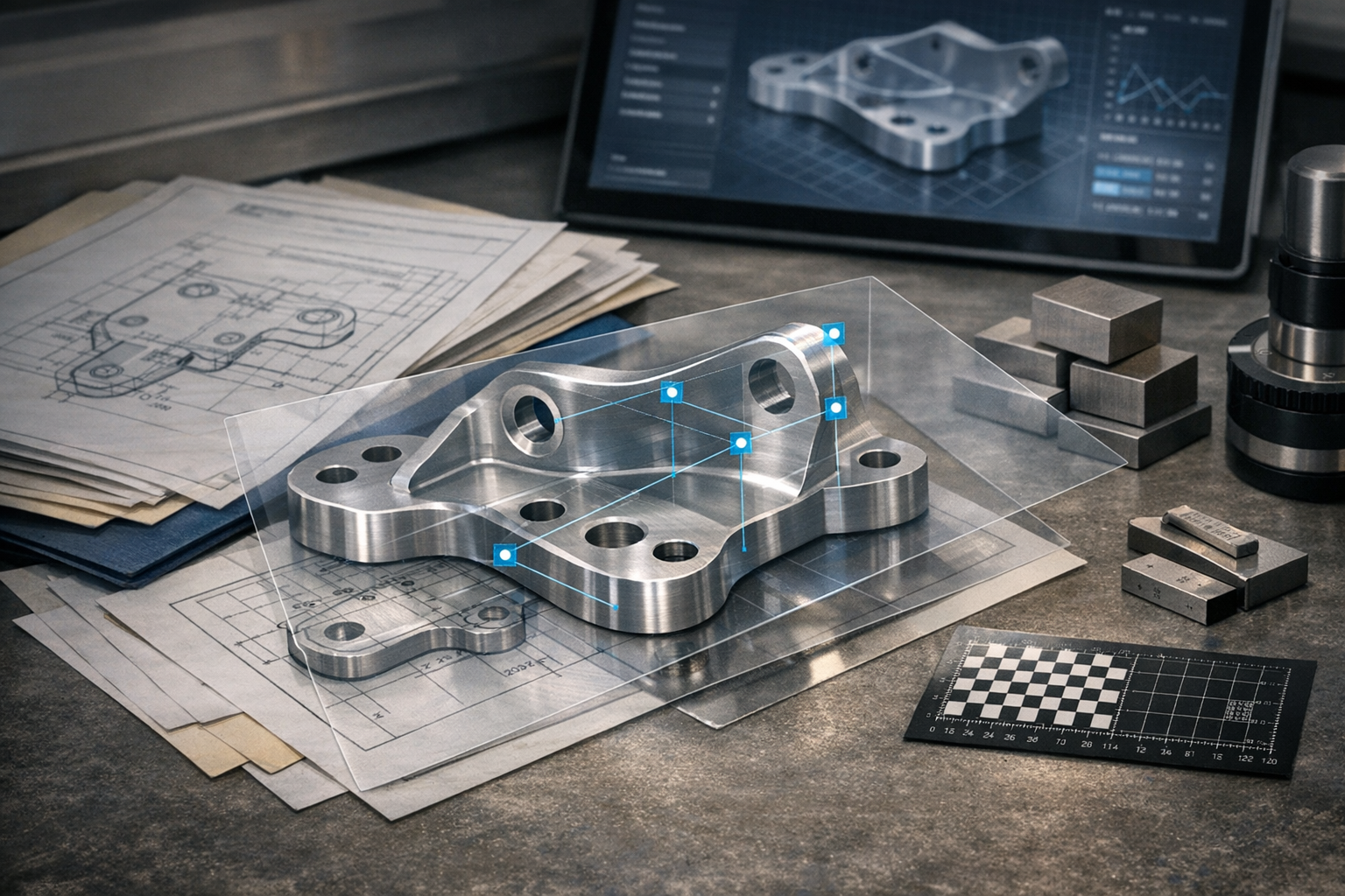
Tag: digital first article inspection

  • The Future of Digital FAI: MBD, AI, and the Aerospace Digital Thread

    The Future of Digital FAI: MBD, AI, and the Aerospace Digital Thread

    The Future of Digital FAI: MBD, AI, and the Aerospace Digital Thread

    First article inspection (FAI) is no longer just a stack of AS9102 forms checked before releasing a new aerospace part to production. Over the next few years, FAI will sit at the intersection of model-based definition (MBD), AI-assisted analytics, and the broader aerospace digital thread that connects design, planning, execution, and in-service data. Teams that still treat FAI as an isolated paperwork exercise will struggle to keep pace with program complexity and customer expectations.

    This article explores how digital FAI is evolving, and what quality, manufacturing, and engineering leaders should expect from the next generation of AS9102 software. It builds on foundational concepts from AS9102 software for digital first article inspection, and looks ahead to how MBD, AI, and connected factory systems will reshape day-to-day workflows.

    For teams putting this topic into daily operation, digital AS9102 FAI help connect the concept to traceability, work-order reality, and audit-ready evidence.

    For teams putting this topic into daily operation, digital AS9102 FAI, a connected execution platform, Connect 981’s aerospace execution solutions help connect the concept to traceability, work-order reality, and audit-ready evidence.

    The same operating model also depends on real aerospace execution examples, Connect 981’s aerospace operations guidance, practical aerospace operations FAQs, especially when decisions have to move across quality, production, suppliers, and program leadership without losing context.

    From 2D Drawings to Model-Based Definition (MBD)

    Most aerospace organizations still anchor FAI on 2D drawings and PDF packages, even when design authority already maintains a full 3D model. That gap creates redundant work: engineers translate 3D intent back into 2D, then FAI teams balloon the drawing and re-enter characteristic data into AS9102 forms.

    What MBD and PMI Mean for FAI

    Model-based definition (MBD) moves the authoritative product definition into the 3D model itself. Dimensions, geometric tolerancing (GD&T), surface finishes, and notes are captured as product manufacturing information (PMI) attached directly to model features. For FAI, that means:

    • The 3D model becomes the primary source for characteristic extraction, not a downstream 2D derivative.
    • Balloon numbers and Form 3 rows can be generated from PMI tags rather than from optical character recognition on a PDF.
    • Design changes propagate through PLM-managed models in a controlled way, reducing the risk of using the wrong revision during FAI.

    In a mature digital thread, AS9102 software consumes PMI-rich models via PLM or CAD integrations, creating structured characteristic records without manual re-interpretation of 2D views.

    Extracting Characteristics Directly from 3D Models

    As MBD adoption increases, the logical next step is for FAI tools to extract measurable requirements directly from 3D geometry and PMI. In practice, this looks like:

    • Loading a native CAD or neutral MBD format, then parsing PMI to identify all verifiable dimensions, GD&T frames, and notes.
    • Assigning unique characteristic IDs that map one-to-one to Form 3 rows and can be reused across builds, delta FAI, and future programs.
    • Providing 3D navigation from each characteristic to its associated feature, making it easier for inspectors and CMM programmers to understand intent.

    Compared with PDF-based ballooning, 3D extraction improves consistency and reduces interpretation errors, especially for complex structures and tight GD&T schemes. It also aligns FAI more closely with how CMM and metrology software already operate in many aerospace factories.

    Challenges in Transitioning from 2D-Centric Processes

    Moving FAI workflows from 2D drawings to MBD is not just a tooling change; it is an organizational shift. Common challenges include:

    • Mixed-revision environments: Some parts are fully MBD, others remain drawing-centric, and FAI teams must support both simultaneously.
    • Standards and customer expectations: Customers may still specify 2D drawing deliverables or have not formally approved model-based FAIRs as a primary reference.
    • Skills and training: Inspectors and quality engineers may be less comfortable navigating 3D PMI than reading traditional blueprints.

    A pragmatic approach is to run hybrid pilots: use MBD-derived characteristics as the internal source of truth but still generate AS9102-compliant forms and, where needed, drawing-based views for customer submission. Over time, as standards and customer practices evolve, organizations can phase out redundant 2D work.

    AI and Automation in FAI Data Analysis

    AI is often oversold as a push-button solution that will replace engineering judgment. In regulated aerospace manufacturing environments, that is neither realistic nor desirable. The more practical direction is AI and analytics augmenting human decision-making: guiding where to focus attention, checking FAIRs for inconsistencies, and surfacing patterns that would be hard to see manually.

    AI-Assisted Risk-Based Sampling Approaches

    Risk-based inspection is already established in aerospace quality systems; what changes is the data and tooling that inform those decisions. Emerging AS9102 software capabilities include:

    • Using historical FAIRs and in-process inspection results to estimate process capability for families of parts and operations.
    • Suggesting when 100% measurement is warranted (e.g., new suppliers, unstable processes, safety-critical characteristics) versus when statistically justified sampling is appropriate.
    • Highlighting characteristics with marginal capability or frequent near-miss conditions so engineers can tighten sampling or adjust control plans.

    Importantly, these AI-assisted recommendations should be transparent and overrideable. Quality leaders remain responsible for approving inspection strategies; the system provides context, not commands.

    Anomaly Detection in Measurement Data

    FAI results often sit in a repository until an audit or customer issue forces a review. Anomaly detection changes that by scanning results as they are recorded. Typical use cases include:

    • Flagging unusual distributions, such as one dimension consistently trending toward a tolerance limit across multiple builds.
    • Identifying inconsistent units, extreme outliers, or patterns that suggest transcription errors.
    • Surfacing systematic offsets that hint at fixture, probe, or program issues, before they propagate across a fleet of parts.

    Because AI models can misinterpret rare yet valid data, anomaly alerts should be reviewed by engineers who can confirm whether the pattern reflects a true process issue or expected variation. The value lies in earlier visibility, not automatic disposition.

    Automated Validation of FAIR Completeness and Consistency

    One of the most immediate AI-adjacent wins is rule-based and statistical validation of FAIRs before submission. Advanced AS9102 tools can:

    • Check that every ballooned or PMI-derived characteristic appears exactly once on Form 3.
    • Verify that material certs and special process records are attached for all relevant Form 2 entries.
    • Confirm unit consistency, tolerance format, and revision alignment across Forms 1, 2, and 3.

    Much of this can be implemented today with deterministic rules, complemented by AI models that learn typical patterns for a program or supplier and highlight deviations. The result is fewer customer rejections and less manual rework on incomplete FAIRs.

    FAI as a Node in the Aerospace Digital Thread

    Historically, FAI data stayed within the quality function. In a digital thread architecture, first article inspection becomes a key node linking design, process planning, production execution, and in-service performance. That shift turns FAIRs from static evidence into a rich source of engineering, sourcing, and operations intelligence.

    Connecting Design, Planning, Production, and In-Service Data

    In a connected aerospace manufacturing environment, AS9102 software does not operate alone. It exchanges data with PLM, MES, ERP, and maintenance information systems:

    • Design: PLM supplies the authoritative model or drawing, change history, and configuration rules.
    • Planning: Process plans and operation sequences flow from manufacturing engineering tools into the FAI context.
    • Production: MES links FAIRs to specific work orders, machines, tools, and operators.
    • In service: Maintenance and reliability systems can reference original FAI data when investigating recurring issues.

    When these connections are in place, the FAIR becomes a snapshot of how a particular configuration was realized at a moment in time, fully traceable back to design intent and forward to field performance.

    Using FAI Results to Refine Tolerances and Manufacturability

    First article results often reveal whether a design is realistically manufacturable with the intended processes and suppliers. By aggregating FAI data across parts and programs, engineering teams can:

    • Identify features that repeatedly push process capability limits or require excessive rework.
    • Highlight tolerances that are unnecessarily tight relative to functional needs.
    • Feed evidence-based feedback into design for manufacturability (DFM) guidelines and design standards.

    This turns FAI from a compliance gate into a feedback loop: design decisions are informed by past production reality, reducing ramp-up friction on future programs.

    Linking Certifications and Process Data to Maintenance Records

    For long-life aerospace platforms, the ability to trace from an in-service serial number back to its initial FAI and associated certifications is increasingly important. In a robust digital thread:

    • Each FAIR is indexed by part number, serial, lot, and configuration.
    • Material and special process records attached to Forms 1 and 2 are stored as structured data, not just PDFs on a shared drive.
    • Maintenance events in fleet management systems can link back to the original FAIR to investigate whether initial variability correlates with field performance.

    This level of linkage requires disciplined configuration management and common identifiers across systems, but it pays off in faster root-cause analysis and more targeted corrective actions.

    Supplier Collaboration and Real-Time Portals

    Aerospace primes are increasingly pushing digital requirements into their supply base: structured FAIRs, standard templates, and near-real-time visibility into inspection status. The future of digital FAI will depend as much on supplier collaboration as on internal factory systems.

    Shared FAIR Templates and Live Status Visibility

    Instead of each supplier maintaining its own spreadsheet templates, modern platforms provide shared, controlled AS9102 formats via secure portals. Capabilities typically include:

    • Prime-defined templates that enforce mandatory fields, revision usage, and customer-specific clauses.
    • Real-time visibility into FAIR status across suppliers: not started, in progress, submitted, under review, or approved.
    • Standardized data structures that make downstream analytics (e.g., across suppliers or commodity groups) feasible.

    This reduces interpretation errors and ensures that when data reaches the OEM, it is already compatible with their systems and reporting needs.

    Reducing Rework and Clarification Cycles with Primes

    Much of the delay and friction around FAI comes from back-and-forth clarification: missing attachments, ambiguous dimension coverage, or questions about process changes. Digital collaboration environments help by:

    • Embedding validation rules and checklists that suppliers must pass before submission.
    • Providing structured comment threads tied to specific characteristics or documents.
    • Maintaining a single source of truth for each FAIR, rather than multiple email chains and file versions.

    The outcome is fewer rejected FAIRs, more predictable lead times, and better use of both supplier and OEM engineering capacity.

    Security, IP Protection, and Access Control Considerations

    As more design and inspection data flows through shared portals, protecting intellectual property and regulated information becomes critical. Future-ready FAI platforms must support:

    • Granular access control down to part families, programs, or specific FAIRs.
    • Encryption in transit and at rest, with clear segregation between customers and suppliers.
    • Audit trails showing who accessed or modified data, when, and from where.

    Aerospace organizations should evaluate not only functional capabilities but also how FAI tools align with IT security policies, export control requirements, and customer data handling clauses.

    Preparing Your Organization for the Next Generation of FAI

    Transitioning to AI-enabled, MBD-driven FAI will not happen overnight. Organizations need to understand their current maturity, set realistic priorities, and align technology decisions with standards evolution and customer roadmaps.

    Assessing Current Digital Readiness

    A practical first step is a structured assessment of how FAI is executed today:

    • What proportion of FAIRs are created manually in spreadsheets versus via dedicated AS9102 software?
    • How frequently are 3D models with PMI available, and how are they used today?
    • Which systems hold critical FAI-related data (PLM, MES, ERP, QMS), and how well are they integrated?

    Documenting this baseline helps identify where digital upgrades will have the most immediate impact: reducing rework, shortening lead time, or improving audit readiness.

    Prioritizing Capabilities to Invest in First

    Not every organization needs cutting-edge AI on day one. For many aerospace manufacturers, the highest-value early investments are:

    • Reliable digital ballooning and characteristic extraction from drawings or models.
    • Structured AS9102 forms with built-in validation and revision control.
    • Centralized storage and search for FAIRs, certs, and supporting documents.

    Once those foundations are in place, teams can layer on analytics, anomaly detection, and deeper integration with MES and PLM. Attempting advanced capabilities without a stable data foundation usually leads to frustration.

    Building a Roadmap That Aligns with Standards Evolution

    AS9102, AS9100, and customer-specific requirements will continue to evolve as digital practices mature. A useful roadmap:

    • Maps target capabilities (e.g., MBD-based FAI, supplier portals, AI-assisted checks) against planned system upgrades and program milestones.
    • Identifies standards or customer guidance that may affect when certain practices are accepted (for example, model-based submissions).
    • Includes governance for how FAI processes are updated as standards or internal procedures change.

    The goal is to avoid one-off tool deployments and instead build a coherent, long-term path toward connected, data-centric FAI.

    Practical Steps to Experiment with Advanced FAI Capabilities

    Many aerospace teams want to explore advanced digital FAI but are constrained by active programs, existing contracts, and limited engineering bandwidth. Small, well-scoped pilots can prove value without disrupting ongoing delivery.

    Pilot Projects Using MBD-Derived Characteristics

    For programs where the design authority already maintains MBD, consider a pilot that:

    • Uses a limited set of parts to trial PMI-based characteristic extraction into the FAI system.
    • Compares time and error rates against traditional 2D ballooning.
    • Engages both design and quality teams to refine how PMI is structured for inspection use.

    Lessons from this pilot can inform modeling practices, internal standards, and supplier training before rolling out model-based FAI more broadly.

    Using Analytics on Existing FAIR Data

    Even without new measurement equipment or AI models, most organizations have years of FAIRs that are underutilized. A straightforward analytics initiative might:

    • Normalize existing FAIR data into a common structure, even if it began as spreadsheets.
    • Visualize where FAI rejections, late approvals, or near-miss dimensions cluster by part family, supplier, or process.
    • Feed those insights into process improvement projects or design guidelines.

    This kind of work builds the data literacy and governance needed before deploying more advanced anomaly detection or risk-based sampling algorithms.

    Partnering with Software Providers on Roadmap Features

    Given the pace of change around the digital thread and AI, no single vendor will have every capability fully mature today. Aerospace manufacturers can shape solutions by:

    • Participating in customer advisory boards focused on MBD, AS9102 Rev C interpretation, and supplier collaboration.
    • Co-designing pilot features such as AI-assisted FAIR checks or new integration points with PLM and MES.
    • Aligning contracts and deployment plans with clear milestones for advanced capabilities rather than generic promises.

    For platforms like Connect 981 that already embed FAI within a broader aerospace operations environment, this collaboration ensures that future enhancements match real engineering and production needs, not abstract technology trends.

    The trajectory is clear: FAI is moving from static documentation toward an integrated, data-rich capability that supports faster new part introduction, tighter process control, and more effective collaboration across the aerospace supply chain. Organizations that invest now in solid digital foundations—structured AS9102 data, integration with core systems, and disciplined configuration management—will be best positioned to take advantage of MBD and AI as they mature.
  • Designing an AS9102 Workflow: Best Practices from Planning to Submission

    Designing an AS9102 Workflow: Best Practices from Planning to Submission

    Designing an AS9102 Workflow: Best Practices from Planning to Submission

    Aerospace manufacturers, defense programs, and space hardware suppliers all depend on reliable first article inspection (FAI) to prove that new or changed production processes can consistently deliver conforming hardware. AS9102 defines the minimum requirements, but it does not tell your organization how to design the day-to-day workflow across engineering, quality, operations, and suppliers. That design choice determines whether FAIs move smoothly or become a recurring bottleneck.

    This article describes a practical end-to-end AS9102 workflow from planning through execution, review, and submission, and then shows how to standardize it across plants and suppliers using digital tools. It complements the broader perspective on digital article inspection in AS9102 software for digital first article inspection, focusing specifically on workflow design, roles, and governance.

    For teams putting this topic into daily operation, digital AS9102 FAI help connect the concept to traceability, work-order reality, and audit-ready evidence.

    For teams putting this topic into daily operation, digital AS9102 FAI, a connected execution platform, Connect 981’s aerospace execution solutions help connect the concept to traceability, work-order reality, and audit-ready evidence.

    The same operating model also depends on real aerospace execution examples, Connect 981’s aerospace operations guidance, practical aerospace operations FAQs, especially when decisions have to move across quality, production, suppliers, and program leadership without losing context.

    Planning the AS9102 FAI

    A robust AS9102 workflow starts before any balloons are placed on a drawing. Planning clarifies when FAI is required, what will be inspected, and how responsibilities are divided across teams and organizations.

    Determining when FAI is required

    AS9102 specifies common triggers for FAI, but each aerospace organization must translate these into clear rules embedded in its quality management system (QMS) and production planning processes. Typical triggers include:

    • New part introduction to production or to a particular site or supplier.
    • Engineering changes that affect form, fit, or function.
    • Process changes such as new equipment, tooling, or manufacturing location.
    • Changes in material, source, or software that affect product characteristics.
    • Production lapses exceeding the time limit defined in your QMS or customer requirements.

    In a mature workflow, FAI triggers are not left to memory or tribal knowledge. Instead, they are encoded in planning rules inside ERP, MES, or an integrated quality platform so that a work order or configuration automatically indicates whether a full, partial, or delta FAI is required. That automation avoids missed FAIs and late discovery of requirements at shipment.

    Defining scope and classification of characteristics

    For each FAI event, the planning step must define the technical scope. This includes identifying the applicable configuration and deciding how to classify characteristics, such as:

    • Standard characteristics inspected according to drawing tolerances.
    • Key characteristics (KCs) that significantly affect performance, reliability, or manufacturability.
    • Critical characteristics (CCs) that relate directly to safety of flight or regulatory requirements.

    Classification drives the depth of evidence expected on Form 3, sampling plans, and the level of process capability analysis that may accompany the FAIR. In a digital workflow, these classifications should be stored as structured data, not handwritten notes, so that downstream inspection plans and dashboards can easily distinguish KCs and CCs across part families and programs.

    Coordinating with customers on expectations and formats

    Many primes and Tier 1 customers add program-specific requirements on top of AS9102, such as unique FAIR templates, additional traceability fields, or naming conventions. Effective FAI planning therefore includes explicit customer coordination:

    • Confirm whether the customer requires its own template or will accept your standard AS9102-compliant format.
    • Check if any additional evidence—such as capability studies, special process logs, or test data—must be bundled with the FAIR.
    • Align on submission method (portal upload, EDI, email) and review timelines.

    Digital systems can codify these expectations into customer-specific profiles so that each FAIR inherits the correct template and export format based on customer, part family, or contract.

    Preparing Drawings, Data, and Inputs

    Once an FAI is triggered and scoped, the next step is to ensure all technical inputs, documents, and digital structures are in place. Preparation quality strongly influences the cycle time and accuracy of the final FAIR.

    Ensuring correct drawing revision and configuration

    Configuration management is a critical risk area in aerospace production. Before ballooning or inspection planning begins, the team must verify that:

    • The drawing or model being used matches the configuration defined on the contract and work order.
    • All associated specifications and notes are at the correct revision level.
    • Digital systems consistently reference the same revision across PLM, ERP, MES, and FAI tools.

    In connected factories, this is handled by linking FAIRs directly to controlled configuration objects (e.g., engineering change orders or released models). The FAI workflow should prevent creation of a FAIR against an obsolete revision and should preserve traceability when a delta FAI is required after a design change.

    Gathering material, process, and certification requirements

    Beyond the drawing, AS9102 requires evidence that materials and special processes comply with design requirements. During preparation, the responsible engineer or planner should:

    • Identify all material specifications and associated certificates that must be captured on Form 2.
    • List all special processes (e.g., heat treatment, surface treatment, welding, NDT) and correlate them with internal or supplier process approvals.
    • Clarify which process outcomes (hardness, coating thickness, conductivity, etc.) must be recorded as results versus simply documented through certificates.

    Digital FAI tools can help by enforcing required attachments, linking process records and material lots to the FAIR, and flagging missing certifications before approval.

    Setting up digital templates and checklists

    Standardization begins at the template level. Rather than letting each engineer build FAIRs from blank forms or ad hoc spreadsheets, leading aerospace organizations maintain controlled digital templates and checklists that define:

    • Fields and structure of Forms 1, 2, and 3 in alignment with AS9102 Rev C.
    • Additional internal fields required by the QMS (e.g., internal routing numbers, process owner codes).
    • Checklist items for planning, including trigger confirmation, rev checks, and customer-specific expectations.

    Workflow-oriented platforms can automatically instantiate these templates based on part type, risk category, or customer. This reduces variability and accelerates training for new engineers or supplier quality teams.

    Executing the FAI

    Execution is where most effort and error risk concentrates: ballooning the drawing or model, capturing actual results, and managing issues discovered during inspection. A disciplined, digital-first workflow minimizes manual transcription and enforces characteristic accountability.

    Ballooning drawings and extracting characteristics

    The first visible step in execution is creating the ballooned drawing or model view. In a modern workflow, this should be done using software rather than manual markup.

    • Drawings (or 3D models with PMI) are imported into FAI software that identifies dimensions, GD&T, notes, and other inspection-relevant requirements.
    • Each requirement receives a unique balloon number, which becomes a persistent identifier for that characteristic.
    • Engineers review and validate detected characteristics, adding any overlooked notes or process-related requirements.

    The crucial principle is one characteristic, one balloon, one Form 3 line. This mapping is the backbone of traceability. Once balloons are confirmed, the system should auto-generate the Form 3 characteristic list and maintain a reliable link back to the visual representation.

    Collecting measurement and test data

    Next, inspection and test results are gathered for each characteristic. In an optimized AS9102 workflow, manual entry into spreadsheets is avoided wherever possible. Instead, organizations integrate multiple data sources:

    • CMM programs and other metrology systems that push results directly into the characteristic fields on Form 3.
    • Digital checklists or MES terminals used by operators to record in-process inspection measurements.
    • Laboratory test results (e.g., hardness, conductivity, tensile) imported as structured data and linked to the relevant balloons.

    Validation rules in the digital FAIR form help catch issues such as missing units, out-of-range values, or inconsistent decimal precision. When nonconformances are found, they should trigger formal nonconformance records, not just notes in the FAIR.

    Managing rework and nonconformances during FAI

    Inevitably, some FAIs uncover discrepancies. The workflow must define how to respond without losing traceability or compromising compliance.

    • Nonconformances are logged in the QMS with a clear link back to the specific characteristic and FAIR.
    • Rework is planned and executed through controlled work instructions, with repeat measurements recorded against the same balloon numbers.
    • If disposition decisions (e.g., use-as-is, repair, deviation) are required, these are documented in the QMS, while the FAIR records the final accepted result.

    The FAIR itself should not become a substitute for nonconformance or deviation processes. Instead, it acts as a structured summary of final, accepted results, with references to the supporting quality records.

    Review, Approval, and Submission

    Even well-executed inspections can fail if review and approval are inconsistent or poorly documented. AS9102 workflows should make these steps explicit, role-based, and digitally controlled.

    Internal review and quality signoff

    Before any FAIR is sent to a customer, an internal review ensures completeness and accuracy. Typical checks include:

    • Verification that all applicable characteristics are accounted for and correctly mapped.
    • Confirmation that Forms 1, 2, and 3 are coherent (e.g., part numbers, revisions, and serials match across forms).
    • Checks that required supporting documents—material certs, process logs, test reports—are attached and legible.

    Digital workflows can formalize these reviews using checklists, role-based tasks, and dashboards that highlight missing or inconsistent data. This reduces reliance on individual reviewer experience and improves consistency across sites.

    Electronic signatures and controlled approvals

    Many aerospace organizations operate in environments that require secure, auditable electronic signatures. A best-practice FAI workflow therefore includes:

    • Role-based approval routing (e.g., manufacturing engineering, quality engineering, quality manager).
    • Electronic signatures that are tied to individual user identities and time-stamped, with clear indication of which form or revision was approved.
    • Immutable audit logs that show who changed what and when between draft and approved FAIRs.

    This approach supports both AS9100 expectations and regulatory requirements, and it makes responding to customer or registrar questions significantly easier during audits.

    Submitting FAIRs and responding to customer feedback

    Submission is more than just sending a PDF. The workflow should clarify:

    • Submission channels (customer portal, secure file transfer, or integrated interfaces).
    • Required file formats (native digital format, PDF, data exchange formats) per customer or program.
    • Responsibilities for tracking status, recording customer approvals, and managing rejections or clarification requests.

    Digital platforms can track FAIR status across the supply chain—draft, submitted, under review, accepted, or rejected—giving program and quality leaders visibility into where FAI-related delays might affect deliveries.

    Standardizing Workflows Across Sites and Suppliers

    Designing a single robust AS9102 workflow is only the first step. The real challenge for aerospace companies is ensuring that the same principles are applied consistently across internal plants and external suppliers, without ignoring local constraints or customer-specific clauses.

    Common templates and process maps

    Standardization starts with a documented reference workflow and shared templates. Organizations often define:

    • A core process map that outlines planning, preparation, execution, review, and submission steps.
    • Standard digital templates for Forms 1–3 and for supporting checklists.
    • Risk-based variants of the workflow (e.g., enhanced review for critical parts or programs).

    These artifacts should be centrally controlled but configurable so that sites and suppliers can tailor fields or steps to satisfy local regulatory requirements or customer demands while still staying aligned with the corporate standard.

    Training and competency development

    Even the best-designed AS9102 workflow fails if engineers and inspectors do not fully understand the intent behind each step. Organizations should treat FAI as a core competency, not an occasional paperwork task, by:

    • Providing structured onboarding for new engineers and supplier quality staff on AS9102 concepts and internal workflow expectations.
    • Using real FAIR examples—including both strong and weak submissions—to illustrate acceptable practice.
    • Leveraging digital tools to embed guidance into forms themselves (tooltips, in-form examples, links to procedures).

    Competency assessment can be supported with periodic FAIR reviews, peer audits, or spot checks that focus on systemic understanding, not just form completion.

    Governance for changes to FAI procedures

    As AS9102 evolves and customers update their requirements, FAI workflows must adapt while preserving traceability. Governance mechanisms should include:

    • Formal change control for FAI procedures, templates, and digital workflows.
    • Impact assessment to determine which programs, sites, or suppliers are affected by a change.
    • Versioning of FAIR templates and associated instructions so that past FAIRs remain linked to the procedures in effect at the time.

    Digital workflow engines make it easier to implement these changes consistently and to document which FAIRs were built under each procedural version—critical evidence during audits or investigations.

    Embedding Continuous Improvement into the AS9102 Workflow

    FAI is often viewed as a compliance burden, but it also produces rich data about product design, process capability, and supplier performance. Organizations that treat FAI data as an improvement asset can reduce future defects and streamline new product introduction.

    Capturing lessons learned from each FAIR

    Each completed FAIR should feed a structured lessons-learned process. Typical topics include:

    • Characteristics that were consistently close to tolerance limits, indicating potential process capability concerns.
    • Design features that were difficult to inspect or that required complex setups.
    • Recurring issues with particular suppliers, processes, or materials.

    Digital platforms can capture these insights in a standardized way—through tags, structured comments, or dedicated review steps—and make them discoverable for future programs and engineering change assessments.

    Using metrics to refine workflows and training

    To understand the effectiveness of the AS9102 workflow, aerospace leaders should track quantitative metrics, such as:

    • Average cycle time from FAI trigger to customer-accepted FAIR.
    • Percentage of FAIRs rejected due to documentation or traceability issues.
    • Number of late deliveries where FAI delays were a contributing factor.
    • Frequency and impact of FAI-related audit findings.

    By analyzing these metrics across programs, sites, and suppliers, organizations can identify where training, template refinement, or additional automation will produce the highest return.

    Integrating FAI feedback with design and process engineering

    Finally, the AS9102 workflow should connect back into the broader digital thread of aerospace product development and manufacturing. Examples include:

    • Using FAI measurement data to inform design-for-manufacturability reviews and tolerance optimization.
    • Feeding recurring FAI issues into formal corrective action and process improvement projects.
    • Linking FAIRs to configuration-managed design and planning objects so engineering can see exactly how changes affected process capability.

    Platforms like Connect 981 position FAI as one node in a connected aerospace operations environment, rather than an isolated document. This perspective enables better decisions across engineering, production, and supplier management, while still respecting that each organization must tailor workflows to its own QMS and customer expectations.

    When designing or refining your AS9102 workflow, treat this reference model as a guide, not a rigid prescription. Align each step with your existing QMS, regulatory context, and contractual requirements, and use digital tools to enforce consistency, improve visibility, and capture the data needed for continuous improvement across your aerospace manufacturing network.

  • AS9102 Software: Digital First Article Inspection for Aerospace Manufacturing

    AS9102 Software: Digital First Article Inspection for Aerospace Manufacturing

    Introduction to AS9102 Software and Digital FAI

    Quality engineers, manufacturing engineers, and compliance leaders at aerospace OEMs and suppliers know the operational weight that first article inspection carries. Every new part introduction, engineering change, or process shift triggers documentation requirements that can consume days of engineering time when handled manually. AS9102 software provides the digital infrastructure to manage this burden systematically.

    At its core, first article inspection software automates the creation, management, and submission of article inspection reports compliant with the AS9102 standard. These tools digitize ballooned drawings, where every dimension, tolerance, GD&T symbol, and note receives a unique identifier, and link them to structured Forms 1, 2, and 3 for complete characteristic accountability. The goal is replacing error-prone spreadsheets and paper forms with automated extraction, validation, and workflow routing.

    Connect981 approaches this as part of a unified aerospace operations platform. Rather than treating FAI as an isolated ballooning exercise, the platform embeds digital FAIR forms within the same environment used for work instructions, quality checks, and supplier collaboration. This page serves as a pillar guide to AS9102 software and will link to deeper resources including AS9102 workflow, digital FAIR forms, FAI vs PPAP comparisons, and FAI documentation requirements.

    What you will learn in this guide:

    • Why AS9102 exists and how it evolved to Rev C
    • The operational stakes of FAI in aerospace production
    • Limitations and risks of manual FAI processes
    • Core capabilities of modern article inspection software
    • How digital FAI integrates with manufacturing workflows
    • Audit readiness and traceability requirements
    • Future trends in digital aerospace compliance

    What Is AS9102 and Why It Exists

    AS9102 is an international aerospace standard developed by SAE International under the International Aerospace Quality Group (IAQG), with input from major OEMs including Boeing, Airbus, and Rolls-Royce. The standard defines requirements for planning, performing, and documenting first article inspection to verify that production processes can consistently deliver parts meeting design specifications.

    The standard was initially released in 2004, revised to AS9102B around 2009-2014 with emphasis on planning and execution, and most recently updated to AS9102 Rev C. The transition from Rev B to Rev C, discussed in IAQG resources around 2023-2024, focuses on enhanced clarity for digital implementation and improved handling of partial and delta FAI scenarios.

    Key elements of AS9102:

    • Form 1 (Part Number Accountability): Documents part identification, serial and lot numbers, approvals, and FAI status (full, partial, or delta)
    • Form 2 (Product Accountability): Covers materials, special processes such as heat treatment and NDT, and functional tests with traceable certificates
    • Form 3 (Characteristic Accountability, Verification Results, and Compatibility Evaluation): Links ballooned drawing features to actual measurements, tolerances, and compatibility notes
    • Applicability triggers: New part introductions, significant design changes affecting form, fit, or function, manufacturing process shifts, material or source changes, software updates impacting the product, and production lapses exceeding two years
    • Prime flow-down: OEMs like Boeing often impose stricter customer-specific requirements through purchase orders

    AS9102 integrates with AS9100 quality management systems for process validation and aligns with FAA and EASA airworthiness expectations by ensuring traceability. A critical distinction: FAIR refers to the first article inspection report itself, while FAI refers to the verification process. AS9102 software must support the full lifecycle from planning through signed FAIR submission.

    Why First Article Inspection (FAI) Matters in Aerospace

    FAI serves as formal verification that the production process can consistently produce parts meeting design, safety, and regulatory requirements. This matters most for flight-critical structures, turbine engine components, landing gear hydraulics, and interiors with flammability requirements where downstream defects carry severe consequences.

    The image shows a close-up of aerospace turbine engine components being meticulously measured with precision inspection tools, highlighting the importance of article inspection in ensuring compliance with quality standards. This process is crucial for manufacturers in the aerospace industry to maintain exact specifications and prevent errors during production.

    The fai process catches variances in dimensions, GD&T compliance, material properties, or process outcomes early. Inspecting articles from the first production lot against drawings, specifications, and purchase orders prevents scenarios where issues only surface during volume production or in service.

    Why FAI carries operational stakes:

    • Safety verification: FAI validates that special processes under NADCAP (welding, plating, NDT) were executed correctly and that key characteristics meet exact specifications
    • Program schedule protection: Incomplete or incorrect FAIRs have contributed to unplanned halts at OEM final assembly lines and delayed aircraft deliveries costing significant program resources
    • Airworthiness compliance: FAA and EASA expect demonstrable evidence that initial production articles meet design requirements before approval to proceed
    • Key characteristics (KCs) and critical characteristics (CCs): These flagged items receive heightened scrutiny because they affect safety of flight or regulatory requirements
    • Characteristic accountability: Primes and regulators expect clear traceability from ballooned drawing to measurement result, material certifications, special processes, and approvals

    FAI is not a box-ticking exercise. It provides the documented evidence that a supplier or manufacturing site has the capability to produce conforming product.

    Limitations and Risks of Manual AS9102 FAI Processes

    Manual FAI workflows typically involve printing multi-sheet drawings, hand-ballooning characteristics with colored markers, populating Excel-based FAIR templates, chasing paper certifications via email, and archiving PDFs on shared drives. For complex aerospace parts with 200 or more characteristics and multiple key characteristics, this process can consume 8 to 24 hours or more of engineering time.

    A quality engineer is seated at a desk, intently reviewing large format technical drawings while utilizing measurement tools to ensure compliance with exact specifications. This meticulous process is essential for article inspection and contributes to maintaining quality standards in the aerospace industry.

    The time involved creates capacity constraints, but the error risk poses the greater threat.

    Common failure modes in manual FAI:

    • Missed or duplicated balloons: Industry benchmarks suggest 20-30% error rates in manual ballooning, where characteristics are either skipped or numbered inconsistently
    • Form 3 discrepancies: Actual measurements recorded on Form 3 do not align with the correct drawing revision or balloon numbers
    • Unit and tolerance inconsistencies: Manual data entry leads to mixed units or incorrect tolerance interpretations
    • Tribal knowledge dependency: When the designated FAI expert is unavailable, other technical professionals struggle to replicate the process correctly
    • Revision control breakdowns: Drawing updates get released while FAIRs are in progress, creating mismatches between documented and verified configurations

    Change management issues compound these problems:

    • Delta FAI challenges: When an engineering change affects only a subset of characteristics, manual processes often result in over-documentation (re-inspecting unaffected features) or under-documentation (omitting linked processes)
    • Partial FAI confusion: Relocating a machining operation to a new facility requires partial FAI, but determining which characteristics require re-verification is difficult without systematic tools

    Audit and customer risk exposure:

    • Weak traceability to material certifications and special process documentation
    • Slow FAIR retrieval during AS9100 surveillance audits leading to nonconformance findings
    • Supplier collaboration breakdowns when different spreadsheet formats create multiple versions of truth
    • Industry data suggests 15-25% of FAIRs are rejected for incompleteness when manual processes are used

    Core Capabilities of Modern AS9102 Software

    Robust first article inspection software extends beyond simple ballooning to automate end-to-end FAIR generation per AS9102 Rev C requirements. The following capabilities define what quality managers and manufacturing engineers should expect from a modern system.

    Ballooned drawing automation:

    • Import 2D PDF drawings or CAD derivatives and automatically detect dimensional, GD&T, and note characteristics
    • Assign sequential balloon numbers with the ability for engineers to review, adjust, and override
    • Auto balloon functionality that reduces manual markup from hours to just a few minutes
    • Synchronize extracted characteristics directly to Form 3 rows

    Digital FAIR forms:

    • Configurable templates enforcing AS9102 Rev C requirements for detailed forms including Forms 1, 2, and 3
    • Structured data entry with validation rules that prevent errors such as mismatched revisions or missing mandatory fields
    • Support for multiple units with conversion logic and tolerance formatting
    • Prime-specific formatting options (Boeing, Airbus, etc.) while maintaining a single data model

    Characteristic accountability:

    • One-to-one linkage between each ballooned characteristic and its Form 3 entry
    • Key characteristic and critical characteristic flags with configurable sampling requirements
    • Acceptance criteria and compatibility evaluation fields per Rev C

    Material and process linkage:

    • Attach raw material certifications, special process records (heat treat, NDT, plating), and lab results to Forms 1 and 2
    • Maintain perpetual storage and retrieval for audit readiness
    • Link NADCAP scope documentation to relevant process characteristics

    Revision and change control:

    • Built-in logic to handle delta FAI and partial FAI when only some characteristics change
    • Reuse baseline FAIR data while flagging only affected items for re-verification
    • Maintain full lineage between original and subsequent FAIRs

    Workflow and approvals:

    • Route FAIRs through multi-level review cycles with configurable approval matrices
    • Electronic signatures supporting 21 CFR Part 11 requirements
    • Formal submission workflows to customers or regulatory stakeholders

    Advanced AS9102 software, including Connect981, extends these core capabilities to include real-time dashboards, defect trend analysis, and integration with shopfloor execution. However, these foundational capabilities remain the essential starting point.

    Digital FAIR Forms and Ballooned Drawings

    Ballooned drawings and FAIR forms represent the heart of any AS9102 software implementation. This is where most of the time and error risk concentrate in manual processes.

    A ballooned drawing systematically numbers every verifiable requirement: dimensions and tolerances, GD&T callouts, surface finishes, notes such as “NO SHARP EDGES,” and material or process callouts. Each balloon number drives the structure of Form 3, creating the foundation for characteristic accountability.

    How digital tools automate ballooned drawings:

    • Import PDF or CAD-derived drawings and use OCR and machine learning to detect characteristics with 90% or higher accuracy for printed dimensions
    • Assign sequential balloon numbers automatically with options to hide non-relevant features and focus on applicable requirements
    • Enable engineers to review detected characteristics, adjust balloon placement, and add manually identified items
    • Support multi-sheet drawings common in aerospace with consistent numbering across sheets

    How AS9102 digital FAIR forms should behave:

    • Pre-populate part number, revision, and order details from ERP or MES integration
    • Auto-fill Form 3 lines directly from ballooned drawing data, achieving 80-90% population without manual data entry
    • Enforce correct field usage for Forms 1, 2, and 3 per Rev C requirements
    • Support structured result entries with units, tolerances, and acceptance criteria in reportable fields
    • Export data in customer-required formats with one click submission options

    Characteristic accountability in practice:

    • Each balloon number maps to exactly one row on Form 3
    • Key characteristic flags trigger appropriate sampling plans
    • Results, tolerances, and compatibility notes are captured in linked, structured fields
    • Bidirectional navigation: click a Form 3 row to highlight the corresponding balloon on the drawing

    Connect981 maintains balloon and characteristic data as reusable digital objects. Subsequent delta FAI or repeat builds leverage the same structure without starting from scratch, preserving audit trails across revisions.

    Handling Partial FAI and Delta FAI in Software

    Not every FAI is a full FAI. AS9102 Rev C explicitly accommodates partial FAI and delta FAI to address changes without requiring complete re-verification of unchanged characteristics.

    Partial FAI applies when re-inspection and documentation is needed for only selected characteristics or features. Typical aerospace scenarios include:

    • Moving a machining operation to a new machine or facility
    • Changing tooling that affects specific dimensions
    • Transferring production between supplier sites

    Delta FAI applies when only characteristics impacted by a drawing or specification change require verification, while linking back to the baseline FAIR. Examples include:

    • Tolerance tightening on a specific hole pattern
    • Addition of a new feature to an existing design
    • Material specification updates affecting certain callouts

    How AS9102 software should handle these cases:

    • Tag each FAIR explicitly as full, partial, or delta using Form 1 status fields
    • Reuse existing characteristic data from baseline FAIRs, adding or updating only affected lines
    • Maintain lineage between original and subsequent FAIRs for complete traceability
    • Provide impact analysis tools that parse change notices to flag affected balloons
    • Display FAIR family trees showing relationships across serials and suppliers

    Operational benefits of proper partial and delta FAI handling:

    • 50-80% cycle time reduction for engineering changes compared to full re-FAI
    • Reduced duplication of work across quality engineering teams
    • Stronger audit trails demonstrating exactly what was re-verified and when
    • Better alignment with aerospace change rates (10-20% of parts see annual engineering change orders)

    Connect981 surfaces partial and delta FAIR relationships across multiple factories and suppliers, giving program and quality teams visibility into the complete FAI history of each part number.

    Integration of AS9102 Software with Manufacturing Workflows

    Digital FAI cannot operate in isolation. Effective article inspection report software connects to ERP, MES, PLM, and QMS to eliminate re-keying and ensure fai data accuracy.

    The image depicts a modern factory floor where operators are engaged with digital tablets at their workstations, facilitating the first article inspection (FAI) process. This setup enhances efficiency in the production process by allowing quality managers and technical professionals to streamline data entry and generate accurate article inspection reports.

    Key integration points:

    • ERP integration: Pull part numbers, revisions, purchase orders, and routing information so FAIRs match contractual and planning data
    • MES or shopfloor systems: Link FAIRs to specific work orders, operations, machines, and operators for contextual results
    • PLM integration: Align FAIRs with correct engineering drawing revisions and change notices automatically
    • QMS connection: Connect nonconformance reports and corrective actions to specific characteristics and FAIRs

    Connect981 is positioned as a unified operations layer that sits above existing ERP and MES systems. FAI becomes part of the same digital workflow used for work instructions, inspections, and defect logging.

    Practical workflow examples:

    • A new work order for a flight-critical part automatically triggers FAI requirements based on configuration rules
    • Operators collect measurement data on the shopfloor using digital checklists, feeding results directly into Form 3
    • Quality engineers review and sign off FAIRs in the same system used for other AS9100 documentation
    • CMM systems import cmm data directly into characteristic results, eliminating transcription errors

    Multi-site and supplier integration considerations:

    • Standardized FAIR templates and workflows across internal plants and external suppliers
    • Flexibility to honor customer-specific requirements while maintaining a common data model
    • Portal access for suppliers to submit FAIRs with consistent formatting and required documentation
    • Real-time visibility into FAIR status across the supply chain

    AS9102 Software and Broader Aerospace Compliance

    Digital FAI anchors a compliance ecosystem that includes AS9100, NADCAP, FAA and EASA regulations, and customer-specific quality clauses. Reliable first article inspection fai execution supports multiple compliance objectives simultaneously.

    How FAI connects to broader compliance:

    • Configuration management: Correct part and revision verified against design intent
    • Process validation: Special processes, NADCAP scopes, and supplier approvals recorded and linked
    • Traceability: Serial and lot numbers connected to measurement data, material certifications, and process records
    • Assurance documentation: Evidence of conformance available for customer and regulatory review

    Traceability requirements in detail:

    • Linkage between serial numbers, work orders, FAIRs, material lots, process batches, and inspection equipment
    • Calibration records for measurement tools used during inspection
    • Material certifications traceable to specific lots and suppliers
    • Special process documentation linked to relevant Form 2 entries

    Related topics that support this pillar:

    • FAI documentation requirements: What attachments, certifications, and evidence must accompany a complete FAIR
    • AS9102 workflow: The planning, execution, and submission sequence for compliant FAI
    • AS9102 audit readiness: Preparing for customer and registrar scrutiny of FAI records
    • FAI vs PPAP: How aerospace FAI differs from automotive production part approval processes

    Connect981’s data model was built around aerospace documentation and compliance requirements. FAI data can be reused for audits, customer scorecards, and continuous improvement rather than treated as a one-off artifact that gets filed and forgotten.

    AS9102 Audit Readiness and Digital Traceability

    AS9100, customer, and regulatory audits frequently sample AS9102 FAIRs to evaluate quality system effectiveness. Preparation for these audits determines whether reviews proceed smoothly or generate findings that require corrective actions.

    What auditors typically examine in FAI:

    • Evidence of full characteristic accountability with all ballooned characteristics documented
    • Proper use of Forms 1, 2, and 3 per AS9102 Rev C requirements
    • Clear linkage between drawing revisions, FAIRs, and changes (delta and partial FAI documentation)
    • Traceability to material certifications, special processes, and measurement equipment calibrations
    • Approval signatures and dates demonstrating proper review cycles
    • Document control ensuring only approved templates and forms are used

    How AS9102 software supports audit readiness:

    • Centralized repository of all FAIRs searchable by part, serial, PO, supplier, or date
    • Immutable audit logs recording who created, modified, and approved each FAIR and when
    • Rapid retrieval of ballooned drawings, measurement data, and supporting documents
    • Version control maintaining historical form templates while ensuring current submissions use approved formats
    • Export capabilities for producing complete FAIR packages in pdf or customer-required formats

    Connect981 provides real-time dashboards showing FAI status (open, in review, approved, rejected) across programs and suppliers. Quality leaders can identify overdue FAIRs, bottlenecks in approval workflows, and patterns requiring attention before auditors arrive.

    The practical outcome: response times during audits drop from days of searching shared drives to minutes of filtered queries. This efficiency demonstrates system effectiveness rather than just compliance.

    From Stand-Alone FAI Tools to Connected Aerospace Operations Platforms

    The AS9102 software market includes point solutions focused on ballooning and desktop FAIR creation as well as connected operations platforms that embed FAI in end-to-end production workflows. Understanding the difference helps manufacturers and suppliers align tool selection with long-term digitalization goals.

    Stand-alone FAI tools (examples include InspectionXpert, DISCUS, and similar):

    • Quick adoption for single plants or individual engineers
    • Fast time-to-value for ballooning and form generation
    • Often require manual ERP and MES bridges
    • Create data silos that need reconciliation during audits or supplier coordination
    • Well-suited for companies with limited FAI volume or simpler part portfolios

    Connected operations platforms (including Connect981, Net-Inspect, and others):

    • Use a common data model for work instructions, inspections, nonconformances, and FAIRs
    • Support cross-site standardization of FAI processes and templates
    • Enable analytics across FAI, in-process inspections, and final inspections to identify systemic issues
    • Reduce reliance on spreadsheets, paper packets, and tribal knowledge
    • Require more upfront configuration but deliver compounding efficiency over time

    Evaluating maturity position:

    Maturity Level

    Characteristics

    Typical FAI Time

    Paper and spreadsheets

    Manual ballooning, Excel forms, email coordination

    Days to weeks

    Stand-alone FAI tools

    Automated ballooning, digital forms, local storage

    Hours

    Integrated digital operations

    Connected workflows, unified data, cross-site visibility

    1-2 hours

    Connect981 unifies digital work instructions, FAI execution, quality checks, and supplier collaboration in one environment. For companies at aerospace manufacturers and suppliers managing complex multi-tier supply chains, the platform approach addresses workflows that span multiple systems and sites.

    Teams should evaluate where they sit on this maturity curve and whether AS9102 software selection aligns with broader digital transformation objectives.

    Measuring the Impact of Digital AS9102 FAI

    Aerospace organizations can quantify the ROI of implementing AS9102 software and digital FAI workflows through specific operational metrics. These measurements validate investment and identify areas for continued improvement.

    Recommended metrics to track:

    • Average time to complete a full FAIR (manual baseline vs. digital): Many industries report reduction from 8-24 hours to under 2 hours
    • Average time for delta FAI completion: Should show 50-80% reduction compared to full FAI cycles
    • Rate of FAIR rejections or customer returns due to documentation errors: Digital standardization typically reduces this by 15-25%
    • Number of late deliveries attributed to FAI delays: Tracking this connects FAI efficiency to program schedules
    • Audit findings related to FAI or traceability: Target near-zero findings with proper digital traceability
    • FAI throughput per quality engineer: Measures capacity improvements from automation

    Process capability metrics worth monitoring:

    • Frequency of key characteristics approaching tolerance limits
    • Patterns in characteristic measurements that indicate process drift
    • Correlation between specific operations or suppliers and FAI issues
    • Root cause distribution for nonconformances linked to FAI characteristics

    Platforms like Connect981 provide dashboards showing FAI throughput, bottlenecks, and trends across programs, suppliers, and plants. This visibility enables targeted improvement projects rather than broad-brush process changes.

    Over time, organizations can leverage FAI data to refine design for manufacturability feedback loops with engineering. Rather than treating FAI solely as a compliance requirement, the accumulated data becomes a continuous improvement tool identifying where designs create inspection challenges or where processes need refinement.

    The Future of Digital FAI and Aerospace Compliance

    AS9102 software will evolve significantly over the next three to five years, driven by smart factory initiatives and aerospace digital thread requirements. Understanding these trends helps manufacturers and suppliers make software investments that remain relevant.

    The image depicts a modern aerospace manufacturing facility featuring digital displays and automated inspection stations designed for the first article inspection (FAI) process. This high-tech environment emphasizes quality assurance and efficiency in the production process, showcasing tools and systems that streamline article inspection and data management for technical professionals in the aerospace industry.

    Expected developments in digital FAI:

    • Model-based definition (MBD) and 3D model integration: Reducing reliance on 2D drawings by extracting characteristics directly from 3D models with embedded PMI (product manufacturing information)
    • AI-assisted risk-based sampling: Machine learning suggesting which characteristics warrant 100% inspection versus statistical sampling based on historical data and process capability
    • Anomaly detection in FAI data: Algorithms flagging unusual measurement patterns or potential data entry errors before approval
    • Predictive bottleneck identification: Analytics anticipating FAI delays based on part complexity, team capacity, and historical cycle times
    • Supplier portal integration: Real-time sharing of FAI templates, status, and approvals between primes and tiered suppliers

    How FAI fits the aerospace digital thread:

    • FAI becomes a core node connecting design, planning, execution, quality, and in-service data
    • Measurement results feed back to engineering for tolerance optimization
    • Material and process certifications link forward to maintenance records
    • Configuration control extends from design release through production verification to field support

    Connect981 is being developed to support this direction through AI-assisted insights, low-code workflow modifications as standards evolve, and scalable deployment across global supply chains.

    The companies that treat digital FAI as a game changer rather than simply a compliance checkbox will gain competitive advantage through faster new part introduction, lower quality costs, and stronger customer relationships.

    Assess your current FAI workflows, identify the top bottlenecks in time, errors, or audit pain, and consider piloting a connected AS9102 solution to validate improvements. Manufacturers ready to streamline their fai software approach can request a demo of Connect981 to see how unified operations platforms address the complete FAI lifecycle.