RSC Content Type: Framework

Structured mental model or decision logic.

  • AS9100 Aerospace Quality Standard

    AS9100 Aerospace Quality Standard

    Overview: What AS9100 Is and Why It Exists

    AS9100 is the primary quality management system standard for organizations operating in the aviation, space, and defense sectors. The current version, AS9100 Rev D, was released in 2016 and remains the benchmark for aerospace quality management worldwide. It establishes requirements for how aerospace organizations design, manufacture, assemble, test, and service products that must perform reliably under the most demanding conditions.

    The standard is published by SAE International and was primarily developed through the collaborative work of the International Aerospace Quality Group, which includes representatives from major aerospace manufacturers and suppliers across the Americas, Europe, and Asia-Pacific. AS9100 is built directly on the ISO 9001:2015 framework, incorporating all of its requirements while adding over 100 aerospace-specific mandates that address the unique demands of safety-critical products and complex global supply chains.

    This article focuses on the conceptual and industry-level understanding of AS9100. It does not provide certification guidance, audit preparation advice, or compliance recommendations.

    Core characteristics of AS9100 as a standard:

    • Defines quality management systems requirements specifically for aviation space and defense organizations
    • Builds on ISO 9001 with additional requirements addressing product safety, risk management, configuration management, and traceability
    • Applies across all tiers of the aerospace supply chain, from prime contractors to subcontractors and service providers
    • Serves as a common quality language recognized by aerospace manufacturers, regulators, and defense organizations globally

    Industry Context: Why Aerospace Needs a Dedicated Quality Standard

    The aerospace industry operates under conditions that differ fundamentally from most other industry sectors. Products such as commercial aircraft, military platforms, satellites, launch vehicles, and propulsion systems have lifecycles measured in decades. A single airframe may remain in service for 30 years or more, accumulating hundreds of thousands of flight hours while passing through multiple maintenance, repair, and overhaul cycles. Throughout that lifecycle, every component must perform as designed, every modification must be traceable, and every maintenance action must be documented.

    The regulatory environment reinforces this reality. Authorities like the Federal Aviation Administration in the United States, EASA in Europe, and defense agencies worldwide impose stringent oversight on design, production, and continued airworthiness. These regulatory requirements reflect the consequences of failure: a nonconforming part in a flight control system, a counterfeit fastener in a structural assembly, or a software anomaly in avionics can result in loss of life, mission failure, or catastrophic asset destruction. The aerospace sector operates with zero tolerance for such outcomes.

    A generic ISO 9001 quality management system, while effective for many industries, does not address these specific conditions. ISO 9001 establishes foundational quality management principles around process control, customer satisfaction, and continual improvement. However, it does not require the depth of configuration management, traceability, risk controls, or supplier oversight that aerospace demands. When AS9100 was first released in March 1999, it formalized what aerospace primes and space and defense organizations had already learned: that a sector-specific standard was necessary to codify good practices and reduce organization unique requirements across the supply chain.

    The practical environment where AS9100 applies includes OEM final assembly lines building complete aircraft or spacecraft, tier-1 and tier-2 suppliers manufacturing engines, landing gear, avionics, and structural assemblies, and MRO facilities performing heavy maintenance checks on aging fleets. These operations span multiple countries, involve thousands of suppliers, and require consistent quality systems that can coordinate across organizational and geographic boundaries. The result of traceability gaps, configuration errors, or quality escapes in any part of this network can propagate through the entire product lifecycle.

    The image depicts a commercial aircraft on an assembly line within a large manufacturing facility, showcasing the meticulous processes involved in the aerospace industry. This setting emphasizes the importance of quality management systems and regulatory compliance, ensuring that the aircraft meets the rigorous standards of the aviation space and defense sectors.

    Relationship Between AS9100 and ISO 9001

    AS9100 Rev D incorporates all requirements of ISO 9001:2015 verbatim. Every clause, every expectation, and every process requirement in ISO 9001 appears identically in AS9100. Organizations that achieve AS9100 certification inherently satisfy ISO 9001 requirements as well.

    ISO 9001 functions as a generic quality management system standard applicable to any organization in any sector. It establishes a process-based approach to managing quality, emphasizing customer focus, leadership engagement, planning, operational controls, performance evaluation, and continual improvement. These quality standards provide a solid foundation for organizations seeking to enhance customer satisfaction and deliver products and services consistently.

    AS9100 extends this foundation with aerospace-specific additions that address the elevated risk profile of the sector. Where ISO 9001 introduces risk-based thinking at a conceptual level, AS9100 mandates structured operational risk assessment and mitigation for activities that could affect flight safety, mission success, or regulatory compliance. Where ISO 9001 expects organizations to control documented information, AS9100 adds requirements for configuration management that ensure every product matches its intended design baseline and every change is controlled and traceable throughout the product lifecycle.

    The conceptual scope differences are significant. ISO 9001 aims for consistent product quality and customer requirements fulfillment across diverse industries. AS9100 narrows this focus to aerospace operations, where product quality intersects with product safety, where reliability requirements must account for extreme environmental conditions, and where regulatory compliance is not optional but foundational. Specific thematic additions in AS9100 include:

    • Extended risk management protocols covering operational, safety, and supply chain vulnerabilities
    • Explicit product safety requirements ensuring products perform safely under specified conditions
    • Heightened configuration management controls for tracking design baselines, modifications, and as-built records
    • Strengthened oversight of external providers, including supplier selection criteria, performance monitoring, and flow-down of quality requirements
    • Requirements for counterfeit parts prevention to detect and block unapproved materials from entering the supply chain
    • Focus on critical items whose failure could affect safety or mission success
    • Emphasis on delivery performance and on-time metrics given the tight schedules of aerospace programs

    For readers familiar with ISO 9001, the relationship is straightforward: AS9100 is ISO 9001 plus the additional requirements that aerospace demands.

    Development History and Governance of AS9100

    The first version of AS9100 was published in March 1999, developed by the Society of Automotive Engineers in collaboration with aerospace industry stakeholders. This original release aligned with ISO 9001:1994 and represented the sector’s first unified attempt to standardize quality practices beyond the patchwork of organization unique requirements that primes had historically imposed on their suppliers.

    Subsequent revisions tracked changes in ISO 9001 while incorporating lessons learned from aerospace operations. AS9100 Revision B emerged in the early 2000s, followed by Revision C, which aligned with ISO 9001:2008. The current version, AS9100 Rev D, was released in 2016 to align with the updated QMS model aligned with ISO 9001:2015. Each revision has strengthened requirements around risk management, product safety, and supply chain controls based on industry experience and regulatory expectations.

    The International Aerospace Quality Group governs AS9100’s development and maintenance. IAQG includes representatives from three regional groups: AAQG in the Americas, EAQG in Europe, and APAQG in Asia-Pacific. This structure ensures that the standard reflects global aerospace needs rather than the requirements of any single region or prime manufacturer. Major aerospace manufacturers participate directly in IAQG working groups, contributing operational experience and technical expertise to revision cycles.

    SAE International serves as the publisher for AS9100 in the Americas. In Europe, the equivalent standard is published as EN9100, and in Japan as JISQ9100. Despite different document numbers, these are technically equivalent standards, ensuring that certification to any one of them is recognized globally. This harmonization supports the international standard recognition that aerospace supply chains require.

    Revision cycles are driven by changes in the underlying ISO 9001 framework, lessons learned from aerospace incidents and near-misses, evolving regulatory expectations, and technological advances in areas like composite materials, avionics software, additive manufacturing, and space systems. The forthcoming IA9100 revision is expected to introduce expanded product safety requirements, quality culture and ethical behavior integration, Advanced Product Quality Planning linkages, and a new information security clause reflecting the sector’s digital transformation.

    Conceptual Scope of AS9100 in Aerospace Operations

    AS9100 covers the full aerospace product lifecycle, from initial design and development through manufacturing, assembly, testing, delivery, and post-delivery support. This scope extends to maintenance, repair, and overhaul activities that sustain products throughout decades of operational service. The standard applies wherever aerospace products and services are realized, regardless of whether the organization is an OEM, a tiered supplier, a distributor, or a maintenance provider.

    The types of aerospace organizations that AS9100 targets include:

    • Original equipment manufacturers producing complete aircraft, spacecraft, engines, or major assemblies
    • Tier-1 and tier-2 suppliers manufacturing components such as landing gear, avionics systems, hydraulic actuators, and structural parts
    • Tier-3 and lower suppliers providing raw materials, fasteners, electronic components, and specialized hardware
    • Maintenance, repair, and overhaul organizations performing scheduled maintenance, modifications, and repairs on operational fleets
    • Service providers supporting aerospace programs through engineering, testing, calibration, or logistics functions

    AS9100 emphasizes process-based management. Organizations must define the processes that affect product conformity and safety, establish controls to ensure these processes operate as intended, measure performance to identify gaps, and implement continual improvement to address weaknesses. This approach requires documented process flows, clear responsibilities, defined interfaces between functions, and mechanisms for detecting and correcting nonconformities before they reach customers.

    In daily operations, AS9100 requirements manifest in tangible ways. Build packages contain controlled work instructions with revision control ensuring every operator follows current procedures. Serialized parts carry documented histories that trace their origin, processing, inspection results, and installation location. Nonconformities trigger formal disposition processes that evaluate impact, determine root causes, and implement recurring corrective actions to prevent recurrence. Internal audits verify that processes operate as designed and that records support the objective evidence required by interested parties including regulators, primes, and customers.

    Core Aerospace-Specific Quality Themes in AS9100

    AS9100’s differentiation from ISO 9001 centers on several major aerospace-specific themes that reflect the sector’s risk profile, regulatory environment, and operational complexity. These themes are not isolated clauses but interconnected concepts that shape how aerospace organizations manage quality throughout the product lifecycle.

    The key themes include:

    • Product safety: Requirements ensuring that aerospace products can be safely used under specified conditions, with controls that identify and mitigate potential risks to passengers, crew, and ground personnel
    • Operational risk management: Structured approaches to identifying, assessing, and controlling risks that could affect product conformity, flight safety, mission success, or regulatory compliance
    • Configuration management: Disciplines ensuring that each product conforms to its intended design baseline, with every change controlled, documented, and traceable
    • Reliability and maintainability: Considerations for how products will perform over extended service lives and how maintenance requirements are addressed in design and documentation
    • External provider controls: Expanded oversight of suppliers, subcontractors, and special process houses to ensure quality requirements flow down through the supply chain

    Digital traceability and documentation integrity are woven throughout these themes. Serial and lot management, first article inspection records, lifetime maintenance histories, and engineering change documentation all depend on accurate, accessible, and controlled information systems. The data that supports AS9100 compliance must be consistent across factories, suppliers, and MRO facilities.

    These themes connect directly to typical aerospace workflows: build packages that guide assembly operations, engineering change incorporation that modifies production configurations, maintenance records that document every action performed on an aircraft, and cross-site data consistency that enables global supply chain management.

    Risk-Based Thinking and Operational Risk in Aerospace

    AS9100 extends ISO 9001’s risk-based thinking into structured operational risk management with explicit focus on aerospace-specific hazards. While ISO 9001 expects organizations to consider risks and opportunities when planning their quality management system, AS9100 mandates that this thinking be applied systematically to activities that could affect flight safety, mission success, and regulatory compliance.

    Aerospace operational risks take many forms. Hardware failures in flight-critical systems can result in loss of control. Software anomalies in avionics can corrupt navigation or flight management data. Maintenance errors during heavy checks can introduce latent defects that remain undetected until operational stress reveals them. Disruptions to single-source critical suppliers can halt production lines and delay aircraft deliveries. Human factors in assembly or maintenance can lead to incorrectly installed components, missed inspection steps, or documentation errors that mask nonconformities.

    AS9100 expects organizations to identify, assess, and control these potential risks not only during product design but also throughout production, servicing, and change management activities. A missed torque sequence on a flight-critical fastener, a misrouted wire harness in an avionics bay, or an undocumented deviation from an approved repair procedure all represent operational risks that the standard requires organizations to address through their quality systems.

    The emphasis is on prevention rather than detection. AS9100’s approach to risk management aims to build controls into processes before problems occur, reducing variation and eliminating conditions that could lead to nonconforming outputs.

    Product Safety and Configuration Management

    Product safety in AS9100 refers to the state where an aerospace product can be safely used under specified conditions throughout its lifecycle. This concept extends beyond manufacturing quality to encompass design decisions, maintenance procedures, operational limits, and documentation that together ensure safe operation in service.

    Configuration management is the discipline that binds design intent to physical reality. Every aircraft, engine, or subsystem exists in a specific configuration state defined by its design baseline, approved modifications, and as-built records. Configuration management ensures that:

    • Design data accurately reflects the intended product configuration
    • Production documentation translates design intent into manufacturing instructions
    • As-built records capture the actual configuration of each delivered product
    • Changes are controlled through formal processes that evaluate impact, approve modifications, and update affected documentation

    Concrete examples illustrate why this matters. An aircraft fleet may include airframes at different modification states, some incorporating service bulletins while others remain at the original configuration. Managing this variation requires precise records that show exactly which modifications have been incorporated on each tail number. Avionics systems may run different software versions depending on when they were manufactured or last updated, and tracking these versions is essential for troubleshooting, maintenance planning, and regulatory compliance. Composite structures may be produced using approved process variations that affect material properties, and knowing which variation applies to each part is critical for structural analysis and repair decisions.

    AS9100 conceptually binds design data, production documentation, and actual physical configuration together. When these elements align, products conform to their approved design and can be certified as airworthy. When mismatches occur, the consequences can include grounded aircraft, costly rework, regulatory findings, or safety events.

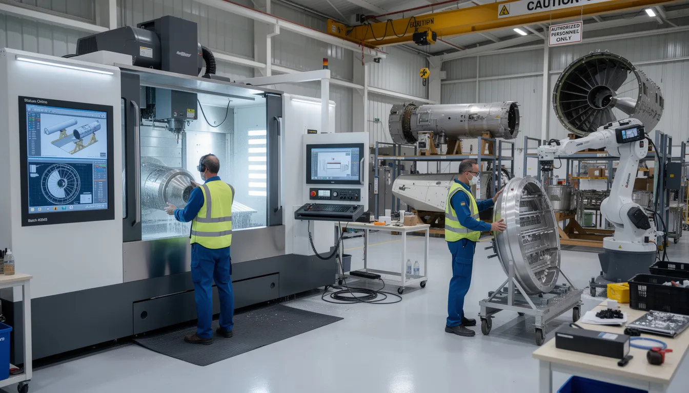
    The image depicts various aerospace engine components meticulously arranged for inspection, highlighting the importance of quality management systems in the aerospace industry. This setup emphasizes adherence to quality standards and regulatory requirements, ensuring product safety and customer satisfaction in the aviation space and defense sectors.

    Counterfeit Parts, Traceability, and External Providers

    The aerospace sector faces particular exposure to risks from counterfeit or unapproved parts. Global supply chains, long product lifecycles, and high component values create incentives for fraudulent materials to enter the system. Examples include unauthorized fasteners that fail to meet strength specifications, electronic components with falsified certifications, and so-called “paper parts” that exist only in documentation while substandard materials are actually supplied.

    AS9100 addresses counterfeit parts prevention through requirements that organizations detect and block unapproved materials before they enter production or maintenance activities. This includes supplier controls, incoming inspection protocols, documentation verification, and awareness training for personnel who handle parts and materials.

    Traceability is the foundation that makes counterfeit detection possible. AS9100 requires that aerospace components carry documented histories tracing their origin, material certifications, processing records, inspection results, and movement through the supply chain. For safety-critical items, this traceability extends throughout the product lifecycle, enabling investigations when anomalies occur and supporting airworthiness determinations during maintenance events.

    The standard also places significant emphasis on controlling external providers. Aerospace organizations depend on suppliers, subcontractors, and special process houses that perform work affecting product conformity. AS9100 requires that quality requirements flow down to these external providers, that their performance is monitored through supplier selection and evaluation processes, and that objective evidence confirms requirements conformance. The OASIS database maintained by IAQG provides a registry where aerospace suppliers can demonstrate their certification status, supporting supply chain visibility across the aerospace and defense industry.

    These themes connect to the reality of globalized aerospace supply networks. OEMs, suppliers, and MRO partners must share reliable data to maintain the integrity of products that may cross dozens of organizational boundaries before reaching operational service.

    AS9100 in the Broader Aerospace Standards Ecosystem

    AS9100 serves as the core quality management system reference for aerospace, but it operates within a broader ecosystem of standards that address specific segments, processes, and requirements. Understanding this ecosystem helps clarify how AS9100 relates to other standards referenced in contracts, specifications, and regulatory frameworks.

    Related aerospace management systems standards include:

    Standard

    Scope

    AS9100

    QMS for design, manufacturing, and service organizations

    AS9110

    QMS for maintenance, repair, and overhaul organizations

    AS9120

    QMS for stockists and distributors

    AS9102

    First article inspection requirements

    AS9103

    Requirements conformance measure variation management

    AS9145

    Requirements for Advanced Product Quality Planning

    These standards share a common foundation in ISO 9001 but add specific requirements relevant to their scope. An MRO organization might hold AS9110 certification, while a hardware distributor might hold AS9120. Both standards build on the same quality management principles but address the distinct operational realities of their sectors.

    Regulators, primes, and defense organizations often expect alignment with AS9100 principles even when contracts reference additional quality standards. NADCAP accreditation for special processes like heat treatment, welding, or nondestructive testing represents another layer of aerospace quality assurance that works alongside AS9100 certification. An aerospace company may require certification to AS9100 as a baseline while also requiring NADCAP accreditation for suppliers performing critical processes.

    AS9100 sits at the center of this layered environment, providing the foundational management system structure that other standards and requirements build upon.

    Digital Operations, AS9100, and the Role of Platforms like Connect981

    Modern aerospace operations increasingly depend on digital systems to uphold AS9100 expectations around documentation control, traceability, quality assurance, and record retention. The volume and complexity of data that aerospace organizations must manage, from build packages and work instructions to serial number histories and nonconformance records, exceeds what paper-based or disconnected systems can reliably handle.

    Connecting ERP, MES, PLM, QMS, and supplier data into a single operational layer helps organizations maintain consistent, audit-ready information across factories and supply chains. When data flows seamlessly between systems, the risk of configuration mismatches, traceability gaps, and documentation errors decreases. Quality leaders can monitor requirements conformance measure metrics in real time rather than discovering problems during internal audits or customer reviews.

    Typical AS9100-relevant workflows that benefit from digitalization include:

    • Electronic work instructions with version control ensuring operators follow current procedures
    • Serialized parts tracking that maintains documented histories from receiving through final assembly
    • Defect logging and nonconformance documentation with automated routing for disposition decisions
    • Supplier quality visibility enabling real-time insight into external provider performance
    • First article inspection records linked to production data for validation of new parts or processes
    • Audit trail generation that demonstrates objective evidence of conformance to interested parties

    The Connect981 platform is an aerospace-focused operations layer that supports these kinds of AS9100-aligned quality and traceability workflows. By connecting shopfloor execution, supplier data, documentation control, and quality processes in a unified system, Connect981 helps aerospace organizations maintain the data integrity and process control that AS9100 conceptually requires. The platform is designed for fast deployment with minimal IT overhead, enabling organizations to digitize critical workflows without the complexity of full MES or ERP replacement.

    This digital infrastructure does not guarantee compliance; that remains the responsibility of each organization’s management system. However, connected operations make it easier to operate within AS9100’s conceptual framework and demonstrate conformance when customers, regulators, or certification bodies require evidence.

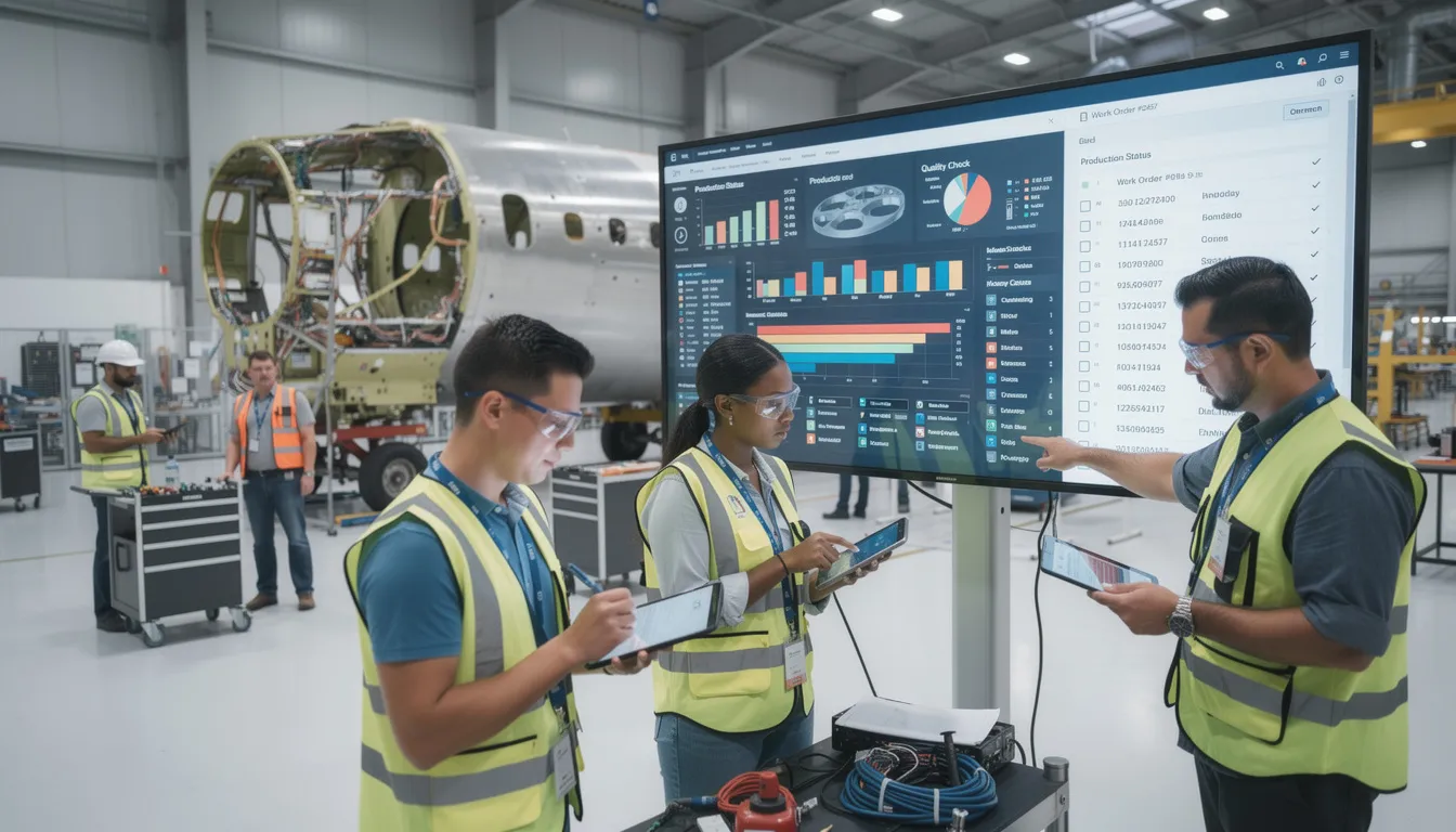
    The image depicts a modern factory floor bustling with workers who are actively engaging with digital displays and tablets, showcasing the integration of technology in the aerospace and defense industry. This environment reflects effective quality management systems and emphasizes continual improvement in customer satisfaction and regulatory compliance.

    Summary: Conceptual Impact of AS9100 on Aerospace Quality

    AS9100 represents the aerospace-specific extension of ISO 9001 that formalizes how organizations manage quality, safety, and risk across complex, regulated product lifecycles. It provides the structural foundation for effective quality management system implementation in aviation, space, and defense while addressing the sector’s unique demands for product safety, configuration control, and supply chain integrity.

    The main conceptual differences from ISO 9001 center on deeper risk integration, explicit product safety focus, rigorous configuration management, heightened traceability requirements, and elevated expectations for supplier oversight. These additions reflect the aerospace sector’s reality: products must perform reliably under extreme conditions, regulatory requirements must be satisfied, and failures carry consequences that extend far beyond typical manufacturing environments.

    Industry-wide, AS9100 provides a common language and structure for OEMs, aerospace suppliers, and MRO providers to align their quality systems, data flows, and daily operations. This standardization reduces organization unique requirements, minimizes supply chain variation, and enables the consistent delivery of products that meet customer requirements and regulatory expectations.

    Evolving aerospace technologies, including advanced materials, digital systems, additive manufacturing, and autonomous platforms, will continue to shape future revisions of AS9100. The digital infrastructures that support these quality systems, including platforms like Connect981, will play an increasingly important role in helping aerospace organizations maintain the documentation control, traceability, and process visibility that the standard demands. Organizations that understand AS9100 conceptually are better positioned to operationalize its requirements and deliver products that meet the aerospace industry’s uncompromising standards for safety and reliability.

    For aerospace manufacturing and MRO teams seeking digital support for AS9100-aligned workflows, request a demo of Connect981 to see how a unified operations layer can strengthen documentation control, traceability, and quality processes across your organization.

  • IATF 16949 Automotive Quality Standard

    IATF 16949 Automotive Quality Standard

    Overview: What is IATF 16949 and why it matters in 2025

    IATF 16949:2016 is the globally recognized quality management system standard for the automotive industry. As of 2025, it remains the foundational framework that original equipment manufacturers and their suppliers use to ensure consistent quality across passenger cars, commercial vehicles, and other on-road automotive applications. The standard applies to organizations involved in the design, development, production, and servicing of automotive production parts and service parts worldwide.

    The standard was published in October 2016, formally replacing ISO/TS 16949:2009. It is maintained by the International Automotive Task Force, a consortium of major automotive manufacturers and national trade associations, in continuing liaison committee status with the International Organization for Standardization. This strong cooperation between IATF and ISO ensures continued alignment with broader quality management principles while preserving automotive-specific requirements.

    IATF 16949 is not a stand alone document. It must be applied in conjunction with ISO 9001:2015 and follows the same structure established by ISO’s Annex SL framework. Organizations cannot achieve certification to IATF 16949 without simultaneously meeting all ISO 9001 requirements. This relationship means that IATF 16949 functions as an automotive-sector supplement that overlays additional requirements onto the ISO 9001 baseline.

    While Connect981 primarily serves aerospace manufacturing and MRO operations, understanding automotive quality management systems provides valuable context for how structured quality frameworks have developed across safety-critical industries. Many of the themes found in IATF 16949, including traceability, supplier oversight, and rigorous process control, parallel requirements in aerospace standards like AS9100.

    The image depicts an automotive production line showcasing vehicles at various stages of assembly, illustrating the intricate production process within the automotive industry. This scene emphasizes the importance of quality management systems, such as IATF 16949, in ensuring high-quality products and customer satisfaction throughout the automotive supply chain.

    Purpose and intent of the IATF 16949 automotive quality standard

    The central purpose of IATF 16949 is to establish a common, globally harmonized set of quality management system requirements for organizations involved in automotive production and service parts. Before harmonization efforts began, automotive suppliers often faced competing quality requirements from different OEM customers, each with their own certification systems. The IATF standard was originally created to consolidate these expectations into a single framework that serves the entire automotive supply chain.

    The core intent focuses on three interconnected objectives: defect prevention, reduction of variation and waste, and robust process control. Rather than treating quality as an inspection-based activity that catches problems after they occur, IATF 16949 emphasizes preventing defects before they reach the production process. This approach acknowledges that in automotive manufacturing, where a single component failure can cascade into recalls affecting millions of vehicles, prevention is far more cost-effective than correction.

    IATF 16949 aligns with customer specific requirements from major OEMs including General Motors, Ford, Stellantis, Volkswagen Group, BMW, and Daimler Truck, among others. By providing a shared baseline for quality expectations, the standard reduces redundancy for suppliers who would otherwise need to manage multiple competing systems. The standard emphasizes customer satisfaction, risk-based thinking, and continual improvement as foundational principles, while leaving specific implementation approaches to individual organizations based on their context and resources.

    From ISO/TS 16949 to IATF 16949: key changes and replacement history

    IATF 16949:2016 formally replaced the previous technical specification, ISO/TS 16949:2009, with the new standard released in October 2016 and transition deadlines set through 2017 and 2018 by IATF and accreditation bodies. The designation change from “ISO/TS” to “IATF” reflects that the document is now owned and maintained directly by the International Automotive Task Force, though it continues to reference ISO 9001:2015 for its base requirements.

    The transition was driven by several factors. First, ISO 9001:2015 introduced a significantly updated structure based on risk-based thinking, requiring alignment from sector-specific standards. Second, the automotive sector needed to address new technologies, including embedded software in vehicle systems, that were not adequately covered in the previous edition. Third, there was recognition that supplier quality and product safety requirements needed strengthening to reflect the increasing complexity of global automotive supply chains.

    Several high-level areas were strengthened in IATF 16949:2016 compared to its predecessor. Product safety received explicit emphasis, with new requirements for organizations to demonstrate that safety-related products and manufacturing processes are controlled appropriately. Traceability requirements were enhanced to address the need for tracking critical components through complex supply networks. Warranty and field failure analysis expectations were formalized, requiring organizations to establish processes for analyzing field incidents, warranty returns, and customer complaints. The standard also introduced considerations for embedded software in automotive related products, acknowledging that modern vehicles depend increasingly on electronic control systems.

    The first edition of the IATF standard represented an innovative document in how automotive quality requirements would be structured and governed globally. Each subsequent update has reflected changes to the underlying ISO 9001 framework while maintaining the automotive-specific emphasis on defect prevention and waste reduction that defines the IATF approach.

    Relationship between IATF 16949 and ISO 9001

    IATF 16949:2016 is a supplemental automotive QMS standard that must always be used together with ISO 9001:2015. Organizations pursuing certification are evaluated against a combined system, and certificates reflect compliance with both IATF 16949 and the underlying ISO 9001 requirements. There is no option to achieve IATF 16949 certification without meeting ISO 9001 in full.

    The structural relationship follows the ISO 9001:2015 High Level Structure, also known as Annex SL, which organizes management system standards into ten clauses. This same structure appears across multiple ISO standards, enabling organizations to align quality management systems ISO 9001 with environmental management under ISO 14001 and occupational health and safety under ISO 45001. The shared architecture reduces complexity for organizations managing an integrated management system across multiple domains.

    ISO 9001 baseline requirements establish foundational quality management principles including customer focus, leadership engagement, process approach, and evidence-based decision making. The seven quality management principles embedded in ISO 9001 provide the conceptual foundation that IATF 16949 builds upon.

    IATF 16949 automotive additions overlay sector-specific requirements throughout the ten-clause structure. These additions include more detailed control of manufacturing processes, specific requirements for supplier quality management, formalized approaches to product safety, and expectations for automotive-specific tools and methodologies. The automotive requirements do not replace or relax ISO 9001 expectations; they extend them to address the particular risks and operational realities of automotive production.

    This relationship enables straightforward integration with other stakeholders’ management system expectations while maintaining the automotive-specific rigor that OEMs require. Organizations already certified to ISO 9001 have a structural foundation in place, though the automotive-specific additions represent substantial additional requirements that reflect the complexity of the automotive sector.

    Scope and automotive supply chain context

    IATF 16949 applies to organizations involved in manufacturing and servicing automotive production parts, service parts, and accessory parts. This includes direct suppliers to OEMs, as well as organizations throughout the supply chain that provide materials, components, or processing services such as heat treating, plating, or painting. Certification bodies evaluate sites where customer-specified automotive products are manufactured, assembled, or supported.

    The standard focuses specifically on serial production for on-road vehicles, including light vehicles, heavy trucks, and buses. Organizations involved in automotive production at any tier level may pursue certification, though the standard explicitly limits applicability to manufacturers. Contract organizations providing only services, distribution, or activities outside direct production are not eligible for IATF 16949 certification.

    Certification expectations cascade through the automotive supply chain. Major OEMs typically require their Tier 1 suppliers to maintain IATF 16949 certification, and those suppliers in turn expect certification from their Tier 2 and Tier 3 sources. This creates a quality expectation that extends deep into global supplier networks, establishing IATF 16949 as the common language for quality management across geographic and organizational boundaries.

    The global nature of automotive production makes harmonized quality requirements essential. Modern vehicles contain thousands of components sourced from suppliers across North America, Europe, China, Japan, and emerging markets. Just-in-time delivery requirements, distributed manufacturing, and complex logistics create conditions where a quality failure at any point can disrupt production across multiple facilities and geographies. IATF 16949 provides the consistent quality performance expectations necessary to manage these risks across the worldwide automotive supply chain.

    The image depicts a complex scene of global shipping containers stacked at a logistics hub, showcasing the intricacies of the automotive supply chain. This visual representation highlights the importance of quality management systems, such as IATF 16949, in ensuring customer satisfaction and continual improvement in the automotive industry.

    Automotive-specific considerations within IATF 16949

    This section provides a high-level overview of themes where IATF 16949 goes beyond generic ISO 9001 requirements. The focus is on concepts and their significance to the automotive sector, not on methods for achieving compliance.

    IATF 16949 addresses several automotive-relevant topics that reflect the industry’s particular risks and operational demands:

    Theme

    Significance in Automotive Context

    Product Safety

    Vehicles carry passengers; failures create direct safety consequences requiring formalized controls

    Component Traceability

    Recalls may affect millions of units; traceability enables targeted response rather than broad recalls

    Manufacturing Process Change Control

    Process variations directly impact product quality in high-volume production

    Externally Provided Products and Services

    Multi-tier supply chains require consistent quality management across organizational boundaries

    Field Performance Analysis

    Large production volumes generate statistically significant performance data requiring systematic analysis

    The standard acknowledges that automotive organizations commonly use specific tools and practices including Advanced Product Quality Planning, Production Part Approval Process, Failure Mode and Effects Analysis, Measurement Systems Analysis, and Statistical Process Control. While IATF 16949 does not prescribe these specific methodologies, they represent expected practices in most OEM-supplier relationships and support the standard’s emphasis on defect prevention and variation reduction.

    Warranty data and field failure information receive particular attention in IATF 16949. The combination of high production volumes and extended vehicle lifecycles generates substantial performance data that organizations must analyze systematically. Customer feedback loops, including warranty returns and field incidents, provide essential input for continuous improvement and help identify problems that may not appear in manufacturing quality metrics.

    While Connect981 focuses on aerospace and MRO operations, many of these themes parallel requirements in AS9100 and other aerospace standards. Serial-number traceability, supplier oversight, rigorous change control, and systematic nonconformance management appear across both industries, reflecting shared recognition that high quality products in safety-critical applications require structured quality systems.

    High-level structure of IATF 16949:2016

    IATF 16949 follows the ten-clause Annex SL structure established by ISO 9001:2015. This common architecture makes it straightforward for organizations to align multiple management systems and reduces the complexity of maintaining parallel quality, environmental, and safety frameworks.

    The standard’s clause structure provides the organizational framework for automotive QMS requirements:

    Clause 4: Context of the Organization establishes requirements for understanding the organization’s context, including the needs and expectations of customers, suppliers, and other stakeholders. Organizations must define the scope of their quality management system and understand the automotive supply chain context in which they operate.

    Clause 5: Leadership addresses top management responsibility for the quality management system, including establishing quality policy, assigning roles and responsibilities, and demonstrating commitment to customer focus.

    Clause 6: Planning covers quality objectives, actions to address risks and opportunities, and planning for changes. Risk management principles are embedded throughout, reflecting the risk-based thinking introduced in ISO 9001:2015.

    Clause 7: Support addresses resources, competence, awareness, communication, and documented information. This includes requirements for infrastructure, manufacturing environment, and the knowledge necessary for effective quality management.

    Clause 8: Operation contains the most extensive automotive-specific additions, covering operational planning and control, requirements for products and services, design and development, control of externally provided processes, production and service provision, release of products and services, and control of nonconforming outputs.

    Clause 9: Performance Evaluation establishes requirements for monitoring, measurement, analysis, and evaluation, including internal audit and management review. Automotive-specific performance indicators supplement generic ISO 9001 expectations.

    Clause 10: Improvement addresses nonconformity and corrective action, emphasizing defect prevention and continual improvement as ongoing organizational priorities.

    Automotive-specific additions are embedded throughout these clauses rather than appearing in a separate section. This integration means that organizations must understand both the ISO 9001 base requirements and the automotive additions that apply to each clause.

    IATF rules and governance context (including Rules 6th Edition)

    The International Automotive Task Force functions as the consortium responsible for maintaining IATF 16949, associated rules, and oversight of the global certification scheme. The IATF membership includes major automotive manufacturers from North America, Europe, and Asia, along with national trade associations representing automotive suppliers in various regions.

    The IATF Rules documents govern how certification bodies conduct audits, issue certificates, and maintain the impartiality required for credible third-party certification. These rules establish consistent practices across certification bodies worldwide, ensuring that an IATF 16949 certificate represents the same level of demonstrated compliance regardless of which accredited certification body performed the assessment or where in the world the certified site operates.

    The IATF Rules 6th Edition takes effect on January 1, 2025, establishing revised expectations for how IATF 16949 audits and certification processes are managed. These updated rules reflect ongoing refinement of the certification scheme based on experience and feedback from manufacturers, suppliers, and certification bodies. The updates address audit practices, certification requirements, and oversight mechanisms that maintain the integrity of the IATF 16949 certification system.

    These rules are directed primarily at certification bodies and auditors rather than at individual manufacturing sites. The successful implementation of IATF 16949 at a manufacturing organization depends on the organization’s quality management system, while the Rules govern how external parties evaluate and certify that system. A recertification audit follows the same fundamental requirements regardless of Rules edition, though specific procedural details may change.

    Comparing automotive and aerospace quality frameworks

    While IATF 16949 is specific to the automotive sector, aerospace organizations typically follow AS9100, which is also built on ISO 9001’s structure but with aerospace-specific clauses and regulatory considerations. Both standards share the common foundation of ISO 9001 quality management principles, creating conceptual parallels even though the industries face different regulatory environments and customer expectations.

    Quality Theme

    Automotive (IATF 16949)

    Aerospace (AS9100)

    Traceability

    Component-level for recall management

    Serial-number level for airworthiness

    Configuration Management

    Process change control emphasis

    Design and build configuration control

    Supplier Oversight

    Cascading certification expectations

    Flowdown of requirements to supply chain

    Nonconformance Management

    Systematic corrective action

    Root cause analysis and preventive action

    Customer Requirements

    OEM-specific requirements

    Regulatory (FAA, EASA) and customer requirements

    Both frameworks emphasize strong traceability, configuration management, supplier quality oversight, and rigorous management of nonconformities and corrective actions. Advanced change control, production process validation, and field performance feedback loops appear as common themes across both industries, even though the specific standards and regulatory bodies differ.

    Connect981 is built around aerospace use cases, including AS9100 compliance, FAA and EASA regulatory requirements, and the particular demands of MRO operations. The same digital capabilities that support aerospace workflows, such as work instructions, defect logging, serial-number traceability, and supplier collaboration, reflect the maturity seen in highly structured frameworks like IATF 16949. Understanding how automotive quality management has evolved provides useful context for how these principles apply across safety-critical manufacturing sectors.

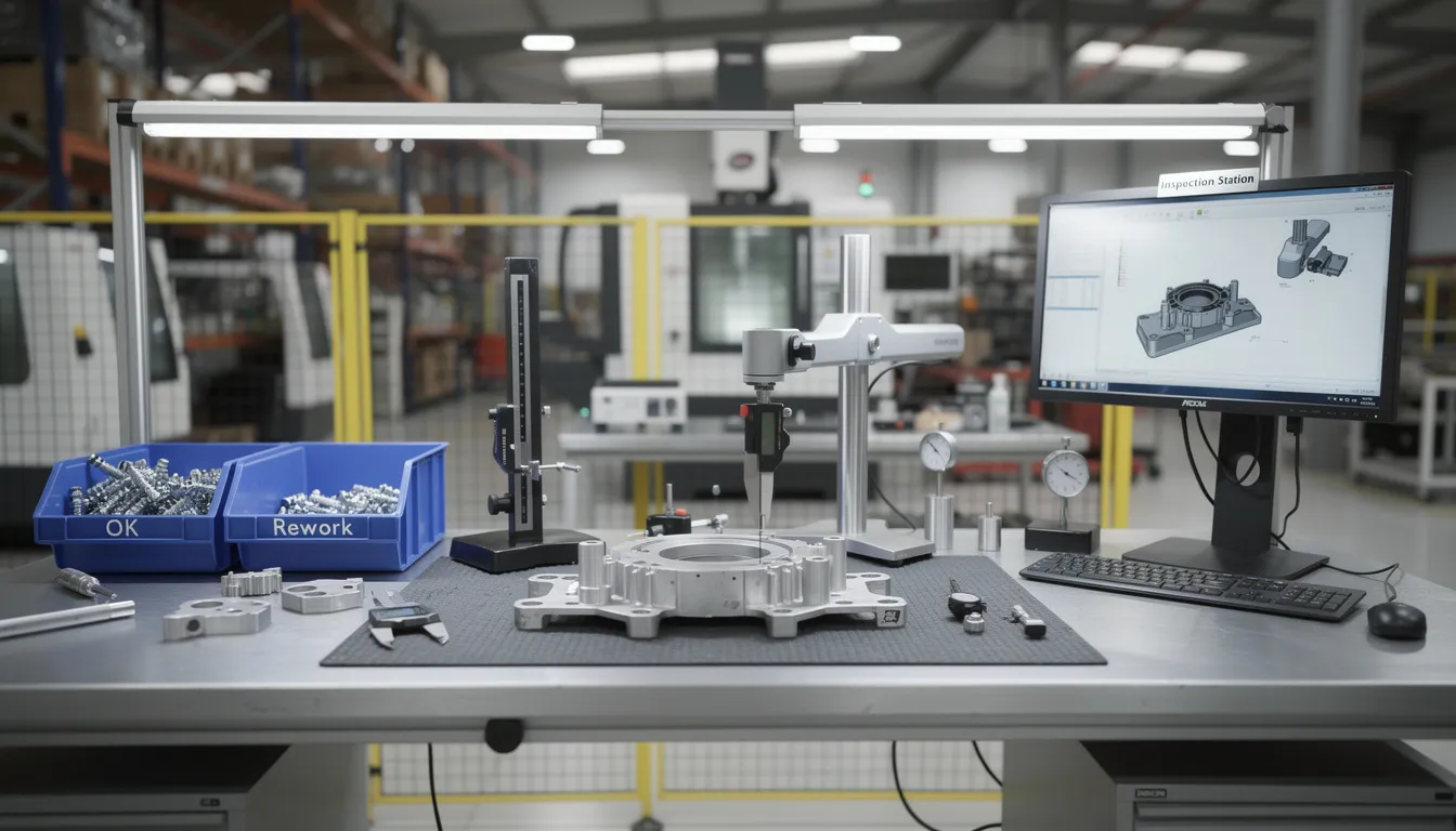
    The image depicts a precision manufacturing inspection process within a quality-controlled environment, showcasing workers meticulously examining automotive components to ensure compliance with IATF 16949 standards. This scene emphasizes the importance of quality management systems in the automotive industry, highlighting defect prevention and continual improvement for high-quality products.

    Summary: IATF 16949’s role in modern automotive quality management

    IATF 16949:2016 remains the globally recognized automotive quality management standard that supplements ISO 9001:2015 and establishes common expectations across the automotive supply chain. The standard replaced ISO/TS 16949:2009 and brought automotive quality requirements into alignment with modern risk-based thinking while strengthening emphasis on product safety, traceability, and supplier quality management. IATF maintains strong cooperation with ISO through its liaison committee status, ensuring that the automotive framework evolves alongside broader international standard developments.

    The standard’s primary contributions include harmonized quality management system requirements that reduce redundancy for global suppliers, an emphasis on defect prevention rather than detection-based quality approaches, and automotive-specific controls that reflect OEM expectations and applicable customer specific requirements. These elements work together to support customer loyalty by ensuring that vehicles meet quality and safety expectations across the production lifecycle.

    While Connect981 operates primarily in aerospace and MRO environments, understanding IATF 16949 helps frame how advanced quality management and digital traceability have developed across safety-critical manufacturing sectors. The principles of efficiency, waste reduction, and systematic quality control that IATF 16949 embodies are not unique to automotive; they represent baseline concepts for any organization seeking to deliver high quality products in complex production environments.

    Structured standards like IATF 16949 will continue to influence expectations for data integrity, supplier collaboration, and end-to-end quality assurance across industrial value chains. As supply chains become more interconnected and production systems more complex, the harmonized approach that IATF 16949 represents provides a model for how industries can establish common quality language and open new markets while managing the risks inherent in globally distributed manufacturing.

  • OPC UA Industrial Interoperability

    OPC UA Industrial Interoperability

    Answering the Core Question: What Is OPC UA and Why Does Interoperability Matter?

    OPC UA, or OPC Unified Architecture, is an interoperability standard developed by the OPC Foundation and first released around 2008. Formalized as IEC 62541, it provides a vendor-neutral, platform independent framework for exchanging industrial data between controllers, equipment, software applications, and enterprise systems. Unlike earlier approaches that tied data exchange to specific operating systems or hardware, OPC UA was designed from the start to work across diverse systems, from embedded controllers running on ARM processors to cloud platforms handling enterprise analytics.

    OPC UA is not just a protocol. It combines communication services with information modeling, defining both how data moves between systems and what that data means. This distinction matters. Many protocols can transfer bytes between two endpoints, but OPC UA goes further by providing a structured way to describe the context, relationships, and semantics of the data value being exchanged. A temperature reading, for example, carries not just a number but metadata about its source, units, quality, and timestamp.

    Industrial interoperability refers to the ability of heterogeneous systems, including PLCs, DCS, scada systems, MES, ERP, analytics platforms, and cloud platforms, to understand and use each other’s data without requiring custom one-off interfaces. In modern industrial contexts such as Industry 4.0 and the industrial internet of things, this capability has become essential. OPC UA’s main conceptual contribution is a common language for data across operational technology and it systems. For aerospace and MRO operations, where reliable traceability, quality, and regulatory compliance are non-negotiable, interoperability is not a convenience but a prerequisite.

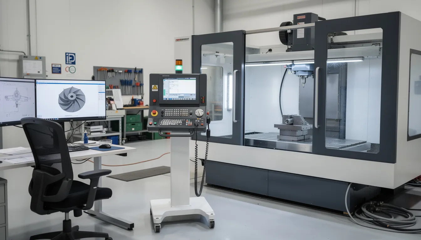
    The image depicts a modern industrial factory floor bustling with various automated machines and advanced control systems, showcasing the integration of OPC UA technology for reliable data exchange and industrial automation. The scene highlights the use of diverse systems and sensors, reflecting the principles of Industry 4.0 and the importance of standardized data in process control.

    From OPC Classic to OPC UA: Evolution Toward Interoperability

    The original OPC standard, sometimes called OPC Classic, emerged in the mid-1990s. At that time, “OPC” stood for “OLE for Process Control,” reflecting its roots in Microsoft’s OLE and COM technologies. OPC Classic was designed primarily to connect Windows-based HMIs and scada systems to process control equipment. For its era, it solved a real problem: before OPC, every integration between a PLC and a visualization system required custom drivers.

    Limitations of OPC Classic:

    Constraint

    Impact

    Windows dependency

    Could not run on Linux, embedded devices, or non-Windows platforms

    COM/DCOM complexity

    Firewall configuration and network security were difficult

    Fragmented specifications

    Separate standards for data access (opc da), historical access, and alarms

    Weak security model

    Not aligned with modern expectations for encryption and authentication

    By 2003, industry groups and the OPC Foundation recognized that a new approach was needed. The goals were clear: cross-platform support for ARM, x86, Windows, Linux, and embedded systems; secure communications with encryption and user authentication; and richer context for industrial data. The result was OPC UA, which unified earlier OPC specifications into one extensible architecture and introduced a modern, service-oriented design.

    OPC UA marked a shift from signal-level connectivity to information-level interoperability. Rather than simply moving data points between two systems, OPC UA enables those systems to understand the structure and meaning of what they exchange. Today, OPC UA support is embedded in industrial devices and software products across discrete manufacturing, process industries, energy, and building automation, making it a de facto reference for reliable data exchange.

    Core Concepts of OPC UA: Services, Models, and Neutrality

    Understanding OPC UA requires grasping a few foundational ideas that distinguish it from simpler protocols.

    Service-Oriented Architecture

    OPC UA defines a set of standardized services that any compliant implementation must support. These services include reading and writing data, subscribing to changes, browsing structures, calling methods, and publishing events. The specification describes what each service does, not how a particular vendor must implement it internally. This approach allows opc ua clients and opc ua server implementations from multiple vendors to communicate without requiring custom adapters.

    Information Modeling and Address Space

    Everything in OPC UA is represented as nodes within a structured address space. Nodes can be objects, variables, methods, or data types, and they are connected by typed relationships. This object-oriented approach allows both simple tags (like a single sensor value) and complex assemblies (like an entire machine with subsystems) to be modeled consistently. The information models describe not just the data source but the context and semantics of the data.

    Separation of Model and Transport

    OPC UA separates the logical information model from the transport layer. The same model can be carried over different encodings and transports, including binary TCP/IP, HTTPS, WebSockets, and even the user datagram protocol in certain contexts. This means the underlying system used for communication can change without altering the meaning of the opc ua data being exchanged.

    Vendor Neutrality

    The OPC Foundation governs OPC UA as an independent body. The opc ua specifications are publicly documented, and any vendor, integrator, or end user can implement servers and clients without proprietary lock-in. This neutrality is central to OPC UA’s value proposition. It does not favor specific products or platforms.

    Coexistence with Legacy Systems

    OPC UA is designed to coexist with legacy fieldbuses, PLC protocols, and higher-level business systems. It does not replace these other systems but provides a shared layer that can expose their data in a consistent, standardized form. For organizations with decades of installed equipment, this coexistence is practical and necessary.

    The image depicts a manufacturing environment featuring advanced industrial automation equipment, including robotic arms and control panels. This setup highlights the integration of OPC UA technology for reliable data exchange and process automation in modern industrial systems.

    Why Industrial Interoperability Is a Strategic Issue

    Between 2010 and 2020, industrial operations became increasingly data-driven. The proliferation of sensors, the rise of MES and analytics platforms, and the push toward digital transformation created new demands for connectivity. At the same time, the heterogeneity of industrial systems became more pronounced.

    A typical plant today might include:

    • PLCs from multiple vendors with different native protocols
    • Specialized test stands and inspection equipment
    • Legacy historians from previous automation projects
    • Different MES deployments across sites or acquired companies
    • Multiple ERPs following mergers or global expansion

    Without standards, each connection becomes a custom interface. This increases project risk, maintenance cost, and the chance of misinterpretation of standardized data.

    Interoperability operates at three conceptual levels:

    Level

    Description

    OPC UA’s Role

    Physical connectivity

    Networks, cables, protocols

    Supports standard TCP/IP and web transports

    Syntactic interoperability

    Data formats and data types

    Defines structured data formats and encodings

    Semantic interoperability

    Shared meaning and context

    Provides information models with defined semantics

    OPC UA addresses primarily the syntactic and semantic levels. It defines standard structures so that data about temperature, torque, or serial numbers conveys the same meaning across industrial systems. For operations leaders, this translates into consistent quality records, reliable OEE metrics, unified traceability, and coherent root-cause analysis across production lines and sites.

    The Role of Open Standards in Industrial Data Exchange

    Open standards like OPC UA serve as long-term infrastructure for industrial data. Their value lies not in any single product but in the common ground they establish for an entire ecosystem.

    What “open” means in practice:

    • Publicly documented specifications (IEC 62541) available for review
    • Governance through a neutral foundation rather than a single vendor
    • Community involvement in developing and extending the standard
    • No licensing barriers to implementation

    Open standards reduce dependence on proprietary gateways and custom integrations. When every participant has a reference for how to structure and interpret industrial data, the engineering effort for each new connection decreases. The opc standard becomes shared infrastructure rather than a competitive differentiator.

    In complex environments, OPC UA commonly coexists with other standards. Industrial Ethernet variants, message queues, and fieldbuses all have their place. Interoperability often comes from combining these technologies rather than replacing one with another. OPC UA’s role is to provide a consistent, higher-level abstraction for data acquisition and exchange.

    Companion specifications, developed by industry working groups, extend the base OPC UA specification with domain-specific information models. These models capture shared concepts for machine tools, robots, energy systems, injection moulding machines, and other assets. When two systems implement the same companion specification, they can understand each other’s structures and semantics without custom mapping.

    For aerospace, energy, and process industry assets that operate for decades, a stable, vendor-neutral data description outlives individual software versions and hardware generations. This long lifecycle support is a strategic advantage of open standards.

    OPC UA Information Modeling and Companion Specifications

    Information modeling in everyday terms means describing what something is, what properties it has, and how it relates to other things. In industrial contexts, this might mean describing a CNC machine with its spindles, axes, tool changers, and the parameters each reports.

    OPC UA represents devices, subsystems, and processes as object-oriented structures. Each element is a node with typed relationships, attributes, and behaviors. A machine might be modeled as an object containing sub-objects for each major component, with variables representing temperatures, speeds, and states.

    How Companion Specifications Work:

    Domain

    Example Models

    Benefit

    Factory automation

    Machine tools, robotics

    Standardized structure for common equipment

    Process automation

    Pumps, valves, reactors

    Consistent representation across vendors

    Energy

    Power meters, inverters

    Comparable data across installations

    Packaging

    PackML state machines

    Interchangeable machine interfaces

    Companion specifications enable plug-and-play style interoperability. When two systems implement the same model, a client can browse and understand their structures without custom development. The opc ua technology carries not just raw data but the context needed to interpret it correctly.

    Different industries are converging on OPC UA-based information models. This reduces engineering effort and ambiguity when connecting assets from multiple vendors. For aerospace and MRO contexts, standardized models for equipment, test benches, quality checks, and asset health can make cross-site data comparison and supplier collaboration more straightforward.

    Security as a Foundation for Trustworthy Interoperability

    Interoperability without protection is risky. Once data flows across departments, networks, and partners, integrity and authenticity become as important as connectivity. The ability to exchange data creates exposure if that exchange is not secured.

    OPC UA addresses this by defining security features as part of the core specification, not as optional add-ons.

    Security mechanisms in OPC UA:

    • Secure sessions with encryption
    • Message signing to ensure integrity
    • Application authentication (certificates)
    • User authentication at multiple security levels
    • Fine-grained authorization for access control

    These mechanisms are built into the specification, enabling consistent approaches across different implementations. This reduces the need for ad-hoc security layers per integration. When an opc ua server and client establish a session, they negotiate security levels appropriate to the sensitivity of the data and the network environment.

    Security in OPC UA is designed to be end-to-end between communicating applications. This is important for systems that bridge operational technology and it systems or span multiple sites. The protection travels with the data, not just at network boundaries.

    Effective security still depends on correct implementation, certificate management, and operational practices. The opc ua protocol provides the tools, but their effectiveness depends on how organizations deploy and maintain them. Secure and reliable communication requires both good standards and good practices.

    Vendor-Neutral Interoperability Across Industrial Systems

    OPC UA conceptually sits between equipment on the shopfloor and higher-level systems. It provides a neutral interface that allows data to flow without tying organizations to a single vendor’s ecosystem.

    Typical system relationships:

    Layer

    System Types

    OPC UA Role

    Field level

    PLCs, CNCs, field devices, various sensors, edge devices

    OPC UA servers expose data

    Control level

    SCADA, DCS, control systems

    Consume and aggregate data

    Operations level

    MES, QMS, workflow platforms

    Use data for execution and quality

    Enterprise level

    ERP, PLM, analytics, cloud platforms

    Consume data for planning and analysis

    An opc ua server acts as a source of standardized information about assets and processes. Opc ua clients are consumers that might be visualization tools, workflow engines, historians, or analytics platforms. The relationship is flexible: a single server can serve many clients, and a single client can connect to many servers.

    This vendor neutrality allows organizations to introduce new components, such as a new analysis tool or a digital work instruction system, without redesigning every interface. As long as the new component speaks OPC UA consistently, it can access the data it needs.

    For long-lived capital environments like aerospace, energy, and process control, choosing a single-stack vendor for every layer is neither practical nor desirable. Equipment from different eras and suppliers must coexist. OPC UA makes it easier for these ot systems and it systems to exchange data in a well-defined way. It does not prescribe operating models, workflows, or business logic. Those remain the domain of the platforms and practices organizations choose.

    The image depicts an aerospace manufacturing facility bustling with workers operating precision equipment, showcasing a blend of advanced technology and industrial automation. The environment highlights the importance of reliable data exchange and the integration of OPC UA protocols for effective communication within industrial systems.

    OPC UA and Aerospace/MRO Digital Operations (Connect981 Perspective)

    Aerospace manufacturing and MRO operations depend on precise traceability, structured documentation, and consistent quality records across factories and suppliers. Serial numbers, batch data, repair histories, and inspection results must be accurate, accessible, and auditable. The regulatory environment, including AS9100, NADCAP, and FAA requirements, makes this non-negotiable.

    We see OPC UA’s standardized information models as a stable way to represent machine states, process parameters, measurements, and asset identifiers. When test cells, assembly equipment, and inspection stations expose their data through OPC UA, we can consume that data and relate it to work orders, build packages, and inspection records within our platform.

    In our view, OPC UA is one of the key mechanisms for bridging operational technology data with higher-level systems like ERP, PLM, and QMS. Connect981 focuses on creating that unified operations layer, linking shopfloor execution, supplier workflows, and compliance documentation. We rely on standards like OPC UA to bring structured, vendor-neutral equipment data into that environment without forcing custom integrations for every asset.

    This approach offers several practical advantages:

    • Reduced reliance on custom integrations and spreadsheets for data acquisition
    • Support for AS9100 and regulatory evidence chains through consistent data capture
    • Easier comparison of performance and quality indicators across sites and suppliers
    • Long-term data continuity as equipment and software evolve over decades

    We do not claim that OPC UA alone solves interoperability challenges. The value comes from pairing the standard with domain-specific platforms and operational design that understand aerospace realities.

    Conceptual Benefits of OPC UA-Driven Interoperability

    Standardized, vendor-neutral data exchange can make it easier to integrate new assets, evolve system architectures, and maintain long-term compatibility in changing industrial landscapes. These are conceptual enablers, not guaranteed outcomes.

    Potential benefits:

    Area

    Conceptual Advantage

    Integration

    Easier to add new equipment or software without redesigning interfaces

    Architecture

    Flexibility to evolve systems over time without vendor lock-in

    Communication

    Clearer data exchange between engineering, operations, IT, and suppliers

    Analysis

    Better-aligned data supports more reliable reporting and decision-making

    Longevity

    Standards outlive individual product versions and hardware generations

    Consistent information models support clearer communication by giving all parties a shared view of what data means. When a production engineer, an IT analyst, and a supplier quality manager all reference the same structured data, misinterpretation decreases.

    Better-aligned data from equipment and industrial systems can support more reliable analysis, real time monitoring, and predictive maintenance. Combined with workflow platforms and analytics tools, this data becomes actionable rather than dormant.

    Actual results depend on design choices, implementation quality, change management, and how organizations align OPC UA with existing processes and governance. OPC UA offers an architectural building block for future-ready industrial operations, not a standalone solution. The standard provides increased efficiency and valuable insights only when paired with thoughtful deployment.

    Looking Ahead: OPC UA in the Broader Interoperability Landscape

    The trajectory for OPC UA points toward continued expansion and refinement. Ongoing developments include expanded companion specifications for new domains, harmonization efforts across industries, and growing use of OPC UA in conjunction with message brokers, edge computing, and cloud-native architectures.

    Emerging trends:

    • Integration with time sensitive network for deterministic communication
    • Functional safety extensions for safety-critical applications
    • Expanded models for process industry and discrete manufacturing
    • Alignment with edge devices and cloud-native patterns

    As factories and MRO networks become more distributed and data-centric, OPC UA’s role as a neutral, model-driven exchange layer is likely to remain relevant. Transport technologies and computing platforms will evolve, but the need for consistent data models and reliable communication will persist.

    Governance matters. Organizations that benefit most from OPC UA-based interoperability will need clear ownership of information models, versioning policies, and cross-site conventions. Without this governance, the technical capability of the standard can be undermined by organizational fragmentation.

    OPC UA provides a common conceptual framework for industrial data, one that, when combined with platforms like Connect981 and thoughtful operational design, can support long-lived, adaptable, and auditable industrial ecosystems. For aerospace operations where compliance, traceability, and multi-site coordination are daily realities, this foundation is increasingly essential.

    For organizations looking to connect shopfloor data with work instructions, quality records, and supplier workflows in a structured, vendor-neutral way, exploring how these standards integrate with a unified operations platform is a practical next step. Request a demo to see how Connect981 approaches this challenge.

  • RAMI 4.0 Reference Architecture: A Structured Explanation

    RAMI 4.0 Reference Architecture: A Structured Explanation

    Overview: What RAMI 4.0 Represents

    RAMI 4.0, the Reference Architectural Model for Industry 4.0, was initially standardized as DIN SPEC 91345:2016 and later aligned with IEC PAS 63088. It emerged from German industry efforts to provide a structured way of describing the components, relationships, and data flows that characterize modern manufacturing systems. The model is a conceptual, three-dimensional reference architecture, not a concrete system blueprint or implementation method.

    The purpose of RAMI 4.0 is to serve as a shared mental model and common language for describing Industry 4.0 systems, physical assets, and data flows across disciplines. Engineers, software vendors, automation specialists, and standards bodies can use the same coordinate system to discuss where a given technology, standard, or function belongs within a broader manufacturing context. This is particularly valuable in environments where information technology and operational technology must converge.

    The model helps position technologies such as digital twin implementations, OPC UA communication protocols, and smart sensors within a consistent architectural frame. However, RAMI 4.0 remains technology-agnostic. It does not mandate specific products, platforms, or integration patterns. This article is written from Connect981’s perspective as an aerospace and MRO operations platform, using RAMI 4.0 purely as a reference explanation without prescribing adoption or implementation steps.

    The image depicts a modern industrial factory floor featuring robotic arms and various automation equipment, illustrating the principles of smart manufacturing and industrial automation. This environment reflects the integration of emerging technologies and communication protocols within the framework of the RAMI 4.0 reference architecture, emphasizing efficiency in manufacturing processes.

    Industry 4.0 Context and Motivation

    The term Industry 4.0 situates current manufacturing transformation within a historical sequence. The First Industrial Revolution brought mechanization through water and steam power. The Second introduced mass production and electrical engineering. The Third applied electronics and information technology to automate industrial processes. The fourth industrial revolution, emerging around 2011 onward, centers on cyber physical systems, the Industrial Internet of Things, and data-driven automation.

    Germany’s “Plattform Industrie 4.0” served as a central driver for this movement. The initiative brought together representatives from mechanical engineering, electrical engineering, and information and communication technology sectors to define a coherent vision for networked production. The goal was not merely to introduce advanced technologies but to enable manufacturing companies to operate with greater efficiency through connected, intelligent systems.

    The complexity of heterogeneous technologies, standards, and domains made a reference architecture necessary. Enterprise IT systems, shopfloor control systems, field devices, and products each brought their own conventions and protocols. Prior models like ISA-95 and IEC 62264 addressed automated interfaces between enterprise and control systems. Life cycle management standards such as IEC 62890 covered industrial system lifecycles. However, neither offered a unified view of Industry 4.0 that could span all these concerns.

    For sectors like aerospace manufacturing and MRO, clear reference models help reason about traceability, digital documentation, and multi-tier supply chain integration. Even if RAMI 4.0 itself does not dictate concrete automation solutions, it provides a vocabulary for discussing where different systems and functions belong in a broader architecture.

    Origins and Standardization of RAMI 4.0

    The development of RAMI 4.0 began around 2013-2015 through the collaborative efforts of German “Plattform Industrie 4.0” working groups, together with VDI (Association of German Engineers) and ZVEI (the German Electrical and Electronic Manufacturers Association). These organizations recognized that without a common framework, Industry 4.0 efforts would fragment into incompatible implementations.

    Key milestones in the standardization process include:

    Milestone

    Year

    Significance

    Initial RAMI 4.0 concept publication

    2015

    ZVEI status report establishing the three-dimensional model

    DIN SPEC 91345

    2016

    German national standard formalizing RAMI 4.0

    IEC PAS 63088

    2017

    International alignment through IEC Publicly Available Specification

    The purpose of RAMI 4.0 from the outset was to harmonize existing and emerging standards, not to replace them. The model gives stakeholders a shared three-dimensional map for positioning international standards and use cases. Government-backed initiatives in Germany aimed to avoid fragmentation by promoting RAMI 4.0 as a common reference, especially for machine builders, automation vendors, and software providers.

    The industrial internet reference architecture (IIRA), developed by the Industrial Internet Consortium, emerged in parallel for broader IIoT contexts. RAMI 4.0 focused specifically on manufacturing and industrial production, reflecting its German manufacturing origins and strong anchoring in European standardization for various industries.

    RAMI 4.0 as a Three-Dimensional Reference Architecture Model

    RAMI 4.0 uses a three dimensional coordinate system to map any Industry 4.0 concept, component, or function. The three axes are:

    • Layers (vertical axis): Representing IT representation of assets
    • Life Cycle & Value Stream (horizontal axis): Representing evolution over time
    • Hierarchy Levels (depth axis): Representing scale from products to connected enterprises

    The visual mental model resembles a three dimensional layer model or grid. Any element can be located by specifying its coordinates on these axes. A sensor’s OPC UA communication function at the work center level during the production phase occupies a specific position within this coordinate system, distinct from an enterprise planning function at the business layer during the design phase.

    The image depicts an abstract three-dimensional grid structure that illustrates a coordinate system with multiple intersecting planes, representing a complex framework for industrial internet reference architecture. This visual metaphor captures the integration of different systems and layers, essential for smart manufacturing and digital transformation in the context of industry 4.0.
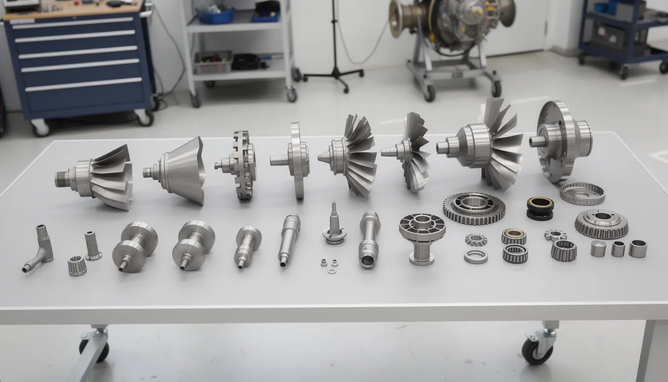
    The axes are grounded in existing international standards. The Layers axis arises from IT architecture practice. The Life Cycle & Value Stream axis builds on IEC 62890 principles for life cycle and value chain management. The Hierarchy Levels axis extends IEC 62264 and ISA-95 automation levels, adding a “Product” level at the bottom and “Connected World” at the top.

    The model is descriptive and classificatory. It helps organize thinking and documentation in a structured manner, but it does not prescribe how to build software, design networks, or select technologies. In Connect981’s context, RAMI 4.0 serves as a reference lens to discuss where functions like digital work instructions, traceability, and supplier collaboration would sit in a broader Industry 4.0 architecture.

    Axis 1: Layers (Vertical IT Representation)

    The Layers axis, sometimes called the vertical axis or left horizontal axis in certain visualizations, decomposes how a physical asset is represented and handled in IT systems. The progression moves from physical properties up through data management and business processes. RAMI 4.0 defines six layers, each with distinct responsibilities.

    Asset Layer

    The asset layer focuses on physical entities. These include machines, fixtures, tools, and products with their mechanical and electrical characteristics. In aerospace manufacturing, this might include a serialized composite part, a torque-controlled assembly tool, or a CNC machine. The layer encompasses the physical world, including metal parts, circuit diagrams, QR codes, and documents that represent tangible reality.

    Integration Layer

    The integration layer couples physical assets to the digital world. This is where sensors, controllers, fieldbus interfaces, and initial data acquisition mechanisms reside. For assets that cannot communicate on their own, such as human operators or purely mechanical components, the integration layer provides interfaces like HMIs or barcode scanners. The digital twin concept begins here, creating IT representation of physical assets.

    Communication Layer

    The communication layer provides standardized communication protocols and services for interoperable data transport. Examples include OPC UA, MQTT, and fieldbus gateways. This layer ensures that communication technology enables different systems to exchange data in common formats, regardless of vendor or origin.

    Information Layer

    The information layer structures, contextualizes, and assigns semantic meaning to raw communication data. Data management practices ensure consistent interpretation across systems. Quality attributes, maintenance histories, and production parameters receive formal definitions at this level, supporting semantic interoperability essential for smart manufacturing.

    Functional Layer

    The functional layer defines services, logic, and behaviors. Functions like routing selection, condition monitoring, predictive maintenance rules, and quality check logic reside here. Formal function descriptions support decision logic execution and service-oriented architecture patterns.

    Business Layer

    The business layer models organizational business processes, compliance rules, and economic decisions. In aerospace contexts, requirements from AS9100, FAA, or ITAR regulations would be represented at this level. The layer links manufacturing processes to legal, regulatory, and business objectives, operating above purely technical implementation.

    The Layers axis separates concerns, allowing standards and solutions to focus on specific layers while still fitting into a coherent whole. This supports loose coupling between layers while maintaining high cohesion within each layer.

    Axis 2: Life Cycle & Value Stream (Horizontal Development and Operation)

    The right horizontal axis, or Life Cycle & Value Stream axis, captures an asset’s evolution over time. It spans from initial concept through end-of-life and distinguishes between “Type” and “Instance” perspectives.

    Type Perspective

    The Type perspective addresses generic product definitions, master data, and design models handled before any specific physical instance exists. In aerospace, this might include:

    • A generic engine bracket specification with defined tolerances
    • Master work instructions for a recurring assembly process
    • Design models for prototype production before first article inspection

    Type information represents blueprints and templates that define what something should be.

    Instance Perspective

    The Instance perspective tracks concrete physical items, batches, or machines once produced and deployed. This includes:

    • Serial numbers for individual components
    • Maintenance records for specific engines
    • Modification histories for a particular aircraft

    Instance information represents specific realizations of Type definitions.

    IEC 62890 provides the foundational standard for life cycle management. RAMI 4.0 overlays Industry 4.0 concepts, such as digital twins, onto this time dimension. The axis also encompasses value stream staging from development and prototyping through production, operation, service/maintenance, and decommissioning.

    For aerospace and MRO operations, this distinction matters when discussing traceability. First article inspection relates to validating that an Instance meets its Type definition. MRO overhaul processes track Instance-specific histories against Type-level requirements. The axis does not define individual process steps but provides a comprehensive framework for discussing which life cycle phase a given function or data set relates to.

    Axis 3: Hierarchy Levels (Depth Across Industrial Scale)

    The left horizontal axis represents hierarchy levels, expanding traditional automation levels from IEC 62264 and ISA-95 to reflect modern, connected manufacturing environments. Where traditional models stopped at the enterprise level, RAMI 4.0 extends in both directions.

    Level

    Description

    Aerospace Example

    Product

    Smart products or parts with embedded identification

    Serialized aerospace component with RFID tag

    Field Device

    Sensors, actuators, and drives interacting with physical processes

    Torque sensors on assembly tools, temperature probes in curing ovens

    Control Device

    PLCs, CNC controllers, motion controllers orchestrating field devices

    CNC controller for a 5-axis milling machine

    Station

    Individual machines, workstations, or inspection cells

    Assembly station, automated optical inspection cell

    Work Centers

    Collections of stations forming process areas

    Composite layup area, wing assembly line segment

    Enterprise

    ERP, PLM, and corporate planning systems

    Multi-site production planning, quality management systems

    Connected World

    External networks including customers, regulators, and suppliers

    Supplier data portals, regulatory submission systems

    The “Product” level at the bottom is a significant extension from traditional ISA-95. It recognizes that smart products can actively influence manufacturing processes through embedded sensors or self-optimizing capabilities. This reflects the industrie 4.0 vision where products carry their own production requirements and quality data.

    The “Connected World” level at the top extends beyond enterprise boundaries. In aerospace, this includes interactions with customers, regulatory bodies, and multi-tier suppliers through standards-based interfaces and shared services. The hierarchy levels represent the spectrum from individual components to global supply chain ecosystems.

    Unlike rigid pyramidal hierarchies of earlier models, RAMI 4.0 assumes cross-level communication and more dynamic interactions. Components at any level can potentially communicate with other components, supporting the network-structured architectures that characterize smart factories.

    The image depicts a large industrial manufacturing facility showcasing multiple operational levels, from floor equipment to control rooms, illustrating the integration of advanced technologies and automation solutions in a smart manufacturing environment. This scene represents the principles of the RAMI 4.0 reference architecture, highlighting the importance of communication technology and data management in optimizing industrial processes.

    Purpose and Use of Reference Architecture Models in Industry 4.0

    A reference architecture model is an abstract, standardized way of describing system structures and relationships, independent of particular products. Reference models serve several important aspects in complex systems environments.

    Shared Vocabulary

    Reference architectures provide a neutral, agreed-upon terminology for engineers, software vendors, and policy makers. When stakeholders discuss “where” a function belongs, a reference model gives them common understanding. The hierarchy levels, layers, and life cycle phases provide a structured approach for cross-disciplinary dialogue.

    Classification

    Existing standards, technologies, and use cases can be mapped to specific segments of the model. This clarifies where overlaps or gaps exist. For example, OPC UA clearly maps to the Communication layer, while IEC 62890 informs the Life Cycle axis. This classification supports step by step migration from legacy systems to smart manufacturing environments.

    Alignment

    In complex, multi-partner ecosystems such as aerospace value chain networks, different stakeholders need common perspective on system architecture. A reference model helps align expectations and documentation without requiring every party to use identical products or platforms.

    Analysis

    Systematic analysis becomes possible by locating elements along the three axes and assessing interactions or dependencies. Questions like “what happens when a field device needs to communicate with enterprise systems?” can be discussed using the model’s structure.

    Reference architectures like RAMI 4.0 do not mandate specific products, communication protocols, or platforms. They provide a standardized framework into which solutions can be placed. For platforms like Connect981, reference models inform conceptual discussions about where digital work instructions, traceability functions, or supplier collaboration portals sit in relation to broader Industry 4.0 structures.

    RAMI 4.0 in Relation to Other Industry 4.0 Architectures

    Multiple reference models coexist in the Industry 4.0 landscape. Understanding their relationships helps clarify RAMI 4.0’s specific focus.

    The Industrial Internet Reference Architecture (IIRA), developed by the Industrial Internet Consortium, is domain-independent. It covers a broad range of IIoT use cases beyond manufacturing, including energy, transportation, and healthcare. The IIRA addresses a connected world of industrial applications without the specific manufacturing focus of RAMI 4.0.

    Aspect

    RAMI 4.0

    IIRA

    Primary Focus

    Manufacturing, industrial production

    Broad IIoT across sectors

    Geographic Origin

    Germany, European standardization

    International, US-based consortium

    Life Cycle Integration

    Explicit axis based on IEC 62890

    Less explicit lifecycle dimension

    Hierarchy Model

    Extended ISA-95 with Product and Connected World

    Different functional domains approach

    International organizations have also developed related frameworks. NIST’s CPS Framework addresses cyber physical systems more broadly. Sector-specific models exist for particular industries. Sometimes mappings are created to translate between these architectures.

    Multiple reference models can be used in parallel. An organization might use IIRA for high-level IIoT planning and RAMI 4.0 to describe detailed manufacturing asset interactions. These models are abstract tools for structuring thought and documentation rather than prescriptive roadmaps for digital transformation or technology selection.

    Conceptual Strengths and Limitations of RAMI 4.0

    Strengths

    RAMI 4.0 provides several conceptual benefits:

    • Systematic Structure: The three-axis approach forces stakeholders to specify where, in terms of layers, life cycle phases, and hierarchy levels, a given concept belongs
    • Standards Grounding: Building on established IEC standards gives the model credibility and integration with existing industrial process measurement and automation frameworks
    • Cross-Disciplinary Dialogue: IT, OT, and business stakeholders can use the same coordinate system to discuss complex systems
    • Neutral Framework: Technology-agnostic positioning allows the model to remain relevant as emerging technologies and artificial intelligence capabilities evolve

    Limitations

    Any architectural abstraction carries inherent limitations. RAMI 4.0 is no exception.

    Abstraction Gap: High-level models cannot capture all real-world constraints. Legacy system quirks, specific aerospace regulations, organizational culture, and machine learning integration challenges do not map neatly onto a three-dimensional cube. The gap between model and reality requires additional guidance.

    Static Representation: The model is largely static and structural. Industry 4.0 systems often exhibit dynamic, adaptive behaviors. Real-time reconfiguration, autonomous decision-making by control systems, and event-driven architectures are difficult to express in a static coordinate system.

    Interpretation Variability: Organizations may interpret axes and levels differently. What one company considers a “Work Center” another might classify as a “Station.” This leads to inconsistent mappings and the need for supplementary documentation.

    Scope Boundaries: RAMI 4.0 focuses on industrial production. It does not, by itself, fully address service operations, logistics networks, or detailed cybersecurity models. Other components of a complete Industry 4.0 strategy require additional frameworks.

    RAMI 4.0 should be seen as one analytical lens among several. It structures discussions and documentation effectively but is insufficient on its own to fully specify or guarantee a working Industry 4.0 system. The model identifies where standards and business models might apply but does not resolve all practical challenges of integration.

    Implications for Digital Industrial Operations (Without Prescriptive Guidance)

    For domains like aerospace manufacturing and MRO, a model like RAMI 4.0 can inform thinking without dictating solutions.

    The Layers axis offers a way to discuss where capabilities typically reside:

    • Digital work instructions might span the Information and Functional layers, providing structured data with associated business logic
    • Traceability functions operate across Integration, Information, and Business layers, linking physical assets to semantic data and compliance requirements
    • Quality checks engage Functional layer logic with Business layer rules

    The Life Cycle & Value Stream axis clarifies whether a given data set or function relates to Type or Instance information. Tracking serialized aerospace components across manufacturing and MRO requires distinguishing between master definitions and instance-specific histories. This distinction matters for data management strategies and audit requirements.

    The Hierarchy Levels axis provides vocabulary for indicating whether a function pertains to field devices, stations, work centers, or enterprise and connected world levels. Multi-site coordination and supplier collaboration involve enterprise and connected world interactions, while shopfloor execution focuses on station and work center levels.

    The image depicts an aerospace manufacturing environment where workers are actively operating advanced equipment amidst digital displays on the factory floor, highlighting the integration of emerging technologies and industrial automation in smart manufacturing processes. This setting reflects the principles of the RAMI 4.0 reference architecture, emphasizing life cycle management and data management in a connected world.

    For platforms like Connect981, RAMI 4.0 acts as a reference backdrop for analysis and communication with stakeholders. When discussing how digital work instructions, traceability, and supplier portals function, the model provides a common language. However, the model does not directly define software modules, integration patterns, or deployment approaches.

    RAMI 4.0 is most valuable as a conceptual reference architecture. It structures how Industry 4.0 scenarios are described and reasoned about in various industries. Practical system design requires additional, more detailed models and decisions beyond the scope of what any single reference architecture can provide. For aerospace and MRO organizations navigating Industry 4.0 concepts, the model offers a starting point for structured discussions rather than a destination.

    For organizations seeking practical aerospace operations platforms that address shopfloor execution, traceability, and supplier collaboration, Connect981 offers a demo to explore how these capabilities work in real manufacturing environments.

  • First Article Inspection (FAI) in Aerospace Manufacturing

    First Article Inspection (FAI) in Aerospace Manufacturing

    First Article Inspection is the formal verification step that confirms a manufacturing process can consistently produce parts meeting all engineering requirements. In aerospace, this process determines whether a supplier’s production methods, tooling, and materials will deliver conforming hardware before committing to full-rate production or after a major change to design, process, or facility.

    The First Article Inspection Report, commonly called the FAIR, serves as the documented evidence of this validation. It captures material certifications, dimensional measurements, special process approvals, and functional test results in a structured format aligned with AS9100-compliant quality management systems. For aerospace organizations, the FAIR is both a quality gate and a long-term traceability record.

    This pillar guide from Connect981 covers the complete FAI landscape: when first article inspection is required, how to execute the FAI process, what documentation AS9102 demands, how to maintain traceability across the supply chain, and how digital tools reduce FAI cycle time without sacrificing compliance.

    What is First Article Inspection (FAI)?

    First article inspection in aerospace is a formal, documented verification that the manufacturing process, tooling, methods, and suppliers can produce a part that conforms to all engineering, material, and functional requirements. The inspection evaluates a production-representative sample manufactured under normal production conditions, not a hand-finished prototype or engineering sample.

    The critical distinction is that FAI evaluates the manufacturing system, not just a single part. The goal is to prove process capability and consistency before mass production begins. A successful FAI establishes the production baseline and becomes the reference for any future partial FAI or delta FAI activities.

    Aerospace FAI is governed by SAE AS9102, with the latest revision (AS9102D) released in March 2024. This standard defines the documentation structure, required content, and acceptance criteria that suppliers must follow.

    Key terms used throughout this guide:

    • First article inspection: The verification event that validates a manufacturing system’s capability
    • FAIR: The documented report package containing Forms 1, 2, and 3 plus supporting evidence
    • AS9102: The SAE standard governing FAI documentation requirements
    • Ballooned drawing: Engineering drawing with numbered identifiers linking each characteristic to inspection data
    • Characteristic accountability: The systematic verification and recording of all design features
    • Key characteristics: Features with highest risk to product performance or safety requiring special controls

    Unlike routine in-process or final inspection, FAI is event-driven. It occurs at specific triggers such as new part introduction, major design changes, or supplier transitions. The inspection scope is exhaustive, covering 100% of drawing characteristics rather than statistical sampling.

    Regulatory and Standards Context for FAI

    First article inspection matters to aerospace regulators, primes, and certification bodies because it provides documented evidence that production processes meet design intent before hardware enters service. The FAI requirement flows from quality standards through purchase orders into contractual obligations.

    The image depicts an aerospace manufacturing facility equipped with quality inspection equipment and documentation stations, highlighting the critical aspects of the first article inspection process. Various tools and documentation are present to ensure compliance with stringent quality control and assurance standards in the aerospace industry.

    The regulatory framework includes:

    • AS9100 series: The primary aerospace quality management system standard, with AS9102 referenced in Clause 8.5.1.3 for production process verification
    • EN9100 and JISQ9100: European and Japanese equivalents that align with AS9102 principles
    • SAE AS9102: The specific standard for FAI documentation, developed by the International Aerospace Quality Group (IAQG)

    OEMs like Boeing, Airbus, Lockheed Martin, and Rolls-Royce flow down FAI requirements through purchase orders and quality clauses. These clauses typically reference AS9102 explicitly and may add customer-specific requirements for FAIR format, approval workflows, or delegated representative involvement.

    FAI connects to multiple regulatory environments:

    • FAA and EASA production approvals under 14 CFR Part 21 and European equivalents
    • US Department of Defense contracts subject to DFARS clauses requiring documented first-article verification
    • Export-controlled work under ITAR or EAR regulations

    For organizations pursuing AS9100 certification, FAI records serve as evidence of process control and design understanding during audits. Auditors specifically verify linkage between the first build and ongoing production control plans.

    In aerospace, FAI (AS9102) often integrates with Advanced Product Quality Planning per AS9145. The FAI serves as the production validation step in APQP Phase 4, demonstrating that the production process can meet design specifications and quality requirements.

    When is First Article Inspection Required?

    Timing and triggers for FAI are defined by AS9102 and customer contracts. Understanding these triggers is essential for compliance and for avoiding rework when a FAIR is rejected for scope issues.

    Typical triggers for a full FAI per AS9102 and common OEM practices:

    Trigger

    Description

    New part number

    First production of a new design or purchase from a new supplier

    New supplier

    First production by a supplier, regardless of prior part history

    New facility

    First production at a new manufacturing location

    New methods/tooling

    Adoption of manufacturing methods or tooling differing from approved baseline

    Material changes

    New raw material forms or supplier sources

    Engineering design changes often require FAI. The extent depends on what changed:

    • Full FAI: Required when changes affect multiple characteristics or fundamental process assumptions
    • Partial FAI: Appropriate when only a subset of characteristics changed (e.g., two bore diameters at Rev C)
    • Delta FAI: Used when production transfers between facilities or when tooling relocates with unchanged manufacturing sequence

    Process change triggers include major changes in NC programs, process routing, manufacturing sequence, special processes (heat treat, plating, welding), or raw material specifications.

    Many OEM supplier quality manuals mandate FAI after a production lapse of 24 months or more. This reflects concern that knowledge degradation, personnel turnover, and equipment drift during extended gaps may introduce undetected changes to process capability.

    A separate cluster article on when FAI is required expands on these triggers with specific AS9102D clause references and OEM examples.

    FAI vs PPAP and Other Approval Processes

    Readers often confuse first article inspection FAI with the Production Part Approval Process. Both serve as quality gates, but they differ in scope and origin.

    PPAP originated in the automotive industry as part of the APQP framework. It covers a broad range of deliverables: process capability studies, measurement system analysis, control plans, and long-term production readiness documentation.

    FAI (AS9102) focuses heavily on characteristic verification and traceability for a single build event. It validates that a manufacturing process can produce conforming parts but does not inherently require statistical capability studies or control plan submissions.

    Key distinctions:

    Aspect

    FAI (AS9102)

    PPAP

    Primary focus

    Characteristic verification, material/process traceability

    Broad production readiness

    Documentation

    Three AS9102 forms plus attachments

    Up to 18 elements including capability studies

    Industry origin

    Aerospace (IAQG)

    Automotive (AIAG)

    Scope

    Single build event validation

    Long-term production capability

    FAI can be considered a subset of a full PPAP package. However, aerospace primes may require both AS9102 FAIR and additional PPAP or AS9145 deliverables for complex programs.

    Common aerospace customer requirements include:

    1. AS9102 FAIR only: Standard for many detail parts and lower-tier suppliers
    2. AS9102 plus capability studies: Required for key characteristics on critical assemblies
    3. Full APQP/PPAP evidence: Mandated for new product development programs with extensive design responsibility

    The cluster article FAI vs PPAP compares required documents line-by-line across both approval process frameworks.

    FAI Documentation and AS9102 Forms

    The FAIR is the core deliverable of first article inspection. Unless a customer-specific template is mandated in the purchase order or supplier quality manual, the three AS9102 forms serve as the documentation standard.

    The three forms work together to establish complete traceability:

    Form

    Name

    Purpose

    Form 1

    Part Number Accountability

    Identifies the part, revision, FAI type, and reason

    Form 2

    Product Accountability

    Documents materials, special processes, and tests

    Form 3

    Characteristic Accountability

    Records inspection results for every balloon

    A ballooned drawing or 3D digital product definition identifies every characteristic with unique balloon IDs. These IDs map directly to line items on AS9102 Form 3, creating traceability between visual part definition and inspection results.

    Common supporting documents attached to a FAIR package:

    • Raw material certificates of conformance and mill test reports
    • Special process certifications (NADCAP approvals for heat treat, NDT, welding)
    • Functional test reports (pressure tests, electrical continuity)
    • Process flow diagrams or routing sheets
    • Setup sheets and work instructions
    • Nonconformance reports and corrective actions if applicable
    • Customer-approved concessions or deviations

    Key characteristics and critical-to-quality features must be explicitly identified using designators like “KC,” “CC,” or customer-specific markings. These designations signal which features warrant special controls during production.

    Connect981 can host digital FAIR templates aligned with AS9102D, auto-populate fields from ERP and MES data, capture ballooned drawing links, and enforce mandatory attachments before FAIR submission.

    A dedicated cluster article on FAI documentation requirements walks through each field in AS9102 Forms 1–3 with completed examples.

    AS9102 Form 1 – Part Number Accountability

    Form 1 establishes the identity and context for the FAI. Required content includes:

    • Part number and nomenclature
    • Drawing or model number with revision level
    • FAI type (full, partial, delta)
    • Reason for FAI (new part, design change, facility transfer, production lapse)
    • Date of FAI and effective date of any triggering change

    Form 1 distinguishes between Detail FAI (single-component parts manufactured as a discrete unit) and Assembly FAI (multi-component assemblies with a bill of materials).

    For assemblies, Form 1 must list:

    • Each lower-level part number
    • FAIR reference if an FAI exists for that component
    • Serial or lot numbers to maintain traceability across levels

    This hierarchical approach ensures that if a sub component fails FAI or has a nonconformance, the impact on overall assembly acceptance is transparent and traceable.

    AS9102 Form 2 – Product Accountability (Materials and Processes)

    Form 2 documents raw materials and special processes used to manufacture the first article.

    Raw material entries include:

    • Material designation (e.g., 7075-T6 aluminum plate, Ti-6Al-4V bar stock)
    • Material specification reference (e.g., AMS-QQ-A-250/12 for aluminum)
    • Heat lot or batch numbers for traceability
    • Certificate of conformance reference

    Special process entries include:

    Process Type

    Example Specification

    Required Documentation

    Anodizing

    AMS2469, Type II or III

    Process spec, supplier code, approval status

    Passivation

    AMS2700

    NADCAP certification, lot number

    Heat treatment

    AMS specification with temp/time

    Furnace certification, chart records

    NDT

    Customer or NADCAP spec

    Operator certification, inspection report

    Welding

    AMS or customer spec

    Filler material, heat input, post-weld treatment

    Functional tests such as pressure tests, torque tests, or electrical continuity for harnesses are linked via procedure numbers and test report identifiers.

    Example row for a machined strut fitting:

    Material

    Spec

    Heat Lot

    CoC Reference

    7075-T651 Aluminum Plate

    AMS-QQ-A-250/12

    H-2024-0847

    CoC-2024-0847-A

    AS9102 Form 3 – Characteristic Accountability

    Form 3 is typically the most time-consuming element of FAIR preparation. Each line corresponds to a characteristic from the ballooned drawing.

    Required fields for each characteristic:

    Field

    Description

    Balloon number

    Links to ballooned drawing

    Drawing sheet and zone

    Location reference for multi-sheet drawings

    Characteristic description

    “Bore OD,” “Thread M10x1.5,” “Flatness of seating surface”

    Specification or tolerance

    Nominal dimension with tolerance band

    Key characteristic designator

    KC, CC, or standard feature

    Inspection method

    CMM, micrometer, visual, functional test

    Measured result

    Actual numerical value or attribute result

    Gage ID

    Traceable to calibration records

    Acceptance status

    Accept, reject, or conditional

    Characteristics are recorded as either attribute data (pass/fail for thread presence) or variable data (numerical measurement for bore diameter). Using the correct data type ensures accuracy and supports process control.

    Inspection methods may include CMM, hand tools (micrometers, calipers), optical comparators, calibrated tools, or automated scanning equipment. Gage ID and calibration state must be traceable to ISO 17025 labs where applicable.

    Manual Form 3 population using spreadsheets is error-prone. Connect981 can ingest CMM output files and auto-fill inspection results linked to balloon IDs, reducing transcription errors and preparation time.

    Raw Material and Dimensional Records in FAI

    Material and dimensional integrity together determine whether the first article is acceptable and reliable in service. Both require rigorous documentation.

    A quality inspector is using a coordinate measuring machine to perform a first article inspection on an aerospace component, ensuring that it meets the specified design requirements and quality standards. This inspection process is crucial for maintaining product reliability and customer confidence in the aerospace industry.

    Raw material record requirements:

    • Mill test reports documenting chemical composition and mechanical properties
    • Certificates of conformance from material suppliers
    • Traceability to heat lot numbers and purchase orders
    • For critical materials (titanium forgings, composite prepreg), complete mechanical test data

    Aerospace-specific scenarios demand heightened traceability. Titanium forgings for engine mounts require heat lot documentation linking specific material to the first article serial number. Composite prepreg materials have shelf-life limitations requiring lot tracking to ensure out-of-life material is not incorporated.

    Dimensional record requirements:

    • 100% of dimensions on the drawing for FAI
    • GD&T features including flatness, position, runout, and perpendicularity
    • Surface finish measurements where specified
    • Thread verification using appropriate gages

    Common measurement tools in aerospace FAI:

    Tool Type

    Application

    CMM

    Complex geometry, GD&T features, high-precision dimensions

    Portable arms

    Large parts, field measurements

    Laser scanners

    Complex surfaces, rapid data capture

    Pin gages

    Go/no-go verification of holes

    Thread gages

    Pitch and major diameter verification

    Hardness testers

    Material property verification per spec

    Dimensional records must include gage IDs and calibration due dates. Inadequate metrology control is a frequent audit finding. A gage out of calibration at time of measurement can invalidate FAI results for that characteristic.

    The cluster article on FAI traceability explores how raw material, process, and dimensional records tie into serialized part histories over an aircraft’s service life.

    Operational Execution: The FAI Workflow in Aerospace

    The FAI workflow spans multiple functions and requires coordination between quality, manufacturing engineering, supply chain, and the customer. Understanding the operational sequence reduces cycle time and prevents rework.

    Planning phase activities:

    • Review contract and purchase order quality clauses to confirm FAI scope
    • Identify OEM-specific FAIR format or submission portal requirements
    • Hold pre-FAI meeting with quality, manufacturing engineering, and supply chain
    • Confirm latest drawing revision and specifications are available

    Manufacturing engineering planning:

    • Develop process routing and machine/tool selection
    • Identify key characteristics and inspection methods
    • Create digital work instructions or travelers specific to FAI build
    • Verify special process approvals are current (NADCAP certifications)

    The first article must be manufactured under normal production conditions using approved programs, fixtures, materials, and qualified personnel. FAI performed on engineering samples or under special lab conditions does not validate the actual production process.

    Inspection and documentation execution:

    • Balloon the drawing with unique characteristic identifiers
    • Execute dimensional, material, and functional tests per inspection plan
    • Capture results with full traceability: gage IDs, calibration status, inspector identification
    • Document any nonconformances and link to corrective actions

    Review and approval sequence:

    • Internal quality review for accuracy and completeness
    • Customer or delegated representative submission
    • Response to clarification requests within required timeline
    • Final sign-off before rate production release

    Connect981 orchestrates this workflow end-to-end, from digital traveler creation and step-by-step work instructions to automated FAIR compilation and customer portal submission.

    Typical Step-by-Step FAI Process

    This sequential checklist reflects what quality and manufacturing engineers execute during a complete FAI:

    1. Confirm FAI requirement and scope: Review PO quality clauses and determine full, partial, or delta FAI type
    2. Gather latest design data: Obtain current drawing revision, 3D model, specifications, and engineering change notices
    3. Balloon the drawing/model: Assign unique identifiers to every characteristic per customer conventions
    4. Define inspection methods and sampling: Specify gages, CMM programs, and measurement approach for each characteristic
    5. Schedule and build the first article: Execute manufacturing plan using standard production processes and qualified personnel
    6. Perform inspections and tests: Measure all characteristics, conduct functional tests, verify material properties
    7. Compile AS9102 Forms 1–3: Populate all fields with full traceability to gages, materials, and processes
    8. Attach supporting documents: Include CoCs, process certifications, test reports, and any nonconformance records
    9. Internal review and sign-off: Independent verification by quality engineer or supervisor
    10. Customer submission and response: Transmit FAIR via agreed method and respond to questions within timeline
    11. Archive FAIR and link to work orders: Store approved FAIR with connection to serial numbers and purchase orders

    Coordination touchpoints occur at planning (scope agreement), mid-build (observation of critical steps), and review (internal verification before customer submission). Any nonconformances discovered during FAI must be documented with corrective actions, even if the FAIR is approved with concessions.

    Delta FAI and Partial FAI in Practice

    Delta and partial FAIs avoid redoing a full first article inspection when only limited changes have occurred. Both maintain compliance while reducing redundant work.

    Partial FAI focuses only on characteristics affected by a change. For example, if drawing Rev B changes only two bore diameters and a tapped hole position, the partial FAI measures only those three features while referencing the prior full FAIR for unchanged characteristics.

    Delta FAI is a customer- or OEM-defined variation used when:

    • Production transfers between facilities (Wichita to Montreal)
    • Tooling relocates to new equipment
    • Previously approved processes are updated within defined tolerances

    Documentation expectations for both types:

    Requirement

    Partial FAI

    Delta FAI

    FAIR type statement

    “Partial” clearly stated

    “Delta” per OEM definition

    Original FAIR reference

    Required

    Required

    Scope definition

    Changed characteristics only

    Facility/equipment changes

    Supporting evidence

    Process documentation for changes

    Equipment qualification records

    Concrete example: Moving a machining operation from Plant A to Plant B in 2027 would trigger a delta FAI capturing facility-related changes while referencing the original FAIR from the initial production baseline.

    Connect981 versions FAIRs, tracks lineage between full and partial/delta FAIs, and presents a clear audit trail for regulators and customers.

    Common FAI Workflow Challenges and Errors

    FAI failures often stem from preventable documentation and process errors rather than fundamental manufacturing problems. Understanding these risks helps organizations avoid costly errors and customer rejections.

    Documentation issues:

    • Using outdated drawings or engineering documentation (revision mismatch)
    • Inconsistent characteristic numbering between ballooned drawings and Form 3
    • Missing revision updates or engineering change notices
    • Incomplete attachment of required certificates and test reports

    Metrology and data errors:

    • Mis-typed numeric results when transcribing from CMM reports to FAIR forms
    • Incomplete gage ID fields or missing calibration evidence
    • Misuse of attribute versus variable data for critical dimensions
    • Measurement results recorded without units or tolerance context

    Process-related problems:

    • Performing FAI on engineering samples that do not represent actual production process
    • Skipping required special process approvals before FAI build
    • Manufacturing under non-standard conditions (different fixtures, unqualified personnel)

    Communication gaps:

    • Unclear FAI scope communicated between OEM and supplier
    • Customer-specific FAIR formats not shared early in program
    • Late change notices during FAI builds causing scope confusion
    • Delayed responses to customer clarification requests

    The cluster article on common FAI errors presents a detailed checklist of avoidable mistakes and detection methods before customer submission.

    Platforms like Connect981 reduce these errors through enforced templates, automated data import from CMM systems, validation checks before submission, and a single source of truth for drawing revisions.

    Traceability and Record Retention for FAI

    Traceability is central to aerospace safety cases and explains why FAI is so documentation-intensive. The FAIR creates an unbroken chain connecting manufactured parts to their materials, processes, and verification records.

    FAI records connect:

    • Part serial numbers or lot numbers
    • Material lots with heat numbers and mechanical properties
    • Special process lots with vendor identification and approval status
    • Inspection results with gage IDs and inspector identification
    • Responsible parties at each manufacturing and verification step

    This chain enables rapid investigation when field issues occur. If a component fails in service, investigators can trace backward from the serial number to the FAI, then to the specific material heat lot, special process vendor, and dimensional verification records.

    Typical retention expectations:

    Context

    Retention Period

    Commercial aerospace

    10+ years, often through aircraft service life (20-40 years)

    Defense contracts

    Program life or indefinite per contract requirements

    Safety-critical components

    Through product lifecycle plus investigation window

    Rapid retrieval capability matters for regulatory audits, customer investigations, and accident analysis. Older revisions and superseded FAIRs must remain accessible even after design updates.

    The risk of scattered PDFs and spreadsheets across network drives creates compliance exposure. Multi-site operations often struggle with FAIR location and version control, particularly after personnel turnover or facility acquisitions.

    Connect981 centralizes FAIR data, links it to work orders and serial numbers, and provides controlled access to OEMs and tiered suppliers via a shared digital layer.

    The cluster article on FAI traceability deep-dives into serial number management, lot tracking, and integration with ERP, MES, and QMS systems.

    Digital Systems and Automation for FAI

    The aerospace industry is transitioning from paper-based FAIs and standalone spreadsheets toward integrated digital workflows. This shift addresses longstanding pain points while maintaining stringent requirements.

    A digital tablet is positioned on an aerospace manufacturing floor, displaying detailed work instructions related to the first article inspection process. This setup emphasizes the importance of quality control and adherence to specified requirements in the aerospace industry’s production process.

    Common manual pain points:

    • Repeated data entry across inspection logs, spreadsheets, and FAIR forms
    • Inconsistent templates across programs and suppliers
    • Difficulty aggregating CMM output files from different equipment brands
    • Long FAIR cycle times (multiple days per part)
    • High rework rates due to formatting or transcription errors

    Digital FAI capabilities:

    • Automated drawing ballooning and characteristic extraction from CAD/DPD
    • Direct import of CMM and scanner data into Form 3 fields
    • Auto-population of material and process information from MES/ERP
    • Validation checks before submission (missing fields, calibration status)
    • Version control with audit trails

    Integration with MES, ERP, and QMS provides shared part master data, process routings, nonconformance linkage, and document control. This reduces duplication and ensures accuracy between systems.

    Connect981 serves as a unified operations platform that:

    • Provides digital work instructions including FAI-specific steps
    • Captures inspection data at the point of use via mobile devices
    • Links FAIRs to work orders, purchase orders, and supplier records
    • Offers a shared portal for OEM-supplier FAI collaboration with permissioned access

    In aerospace MRO environments, digital FAI systems verify first article repairs or modifications, document new repair procedures, and integrate with maintenance records for product reliability traceability.

    The cluster article on digital travelers and FAI focuses on how digital work instructions and FAIRs work together on a connected shopfloor.

    AI and Analytics in FAI

    Emerging AI and analytics capabilities augment FAI workflows while keeping domain experts in control.

    AI-assisted characteristic extraction from CAD models and engineering drawings reduces manual ballooning time. Machine learning models trained on aerospace drawings can identify features, extract dimensions and tolerances, and propose balloon numbering schemes aligned with customer conventions.

    Advanced analytics on FAIR data across programs and suppliers identifies systemic issues:

    • Recurring nonconformances on specific key characteristics
    • Machines or tooling prone to problems (suggesting calibration drift or wear)
    • Material suppliers with higher nonconformance rates

    Connect981 uses AI-assisted root cause analysis to highlight high-risk features before they fail in FAI or production. Predictive insights flag characteristics similar to historical problem areas for additional review.

    AI augments but does not replace domain experts. Quality engineers, metrologists, and manufacturing engineers retain judgment over design changes, process controls, and supplier qualification decisions.

    Reducing FAI Cycle Time Without Sacrificing Compliance

    FAIs often sit on the critical path for program launches and design changes. A program awaiting FAI approval cannot begin full production run, which delays revenue and may incur customer penalties.

    Typical drivers of long FAI cycle times:

    • Late or unclear requirements from OEMs
    • Fragmented systems (drawings, specs, FAI forms in different locations)
    • Manual data entry and transcription at multiple steps
    • Uncoordinated metrology scheduling
    • Back-and-forth clarifications with customers

    Best practices for acceleration:

    Practice

    Impact

    Early planning and scope confirmation

    Prevents rework from unclear requirements

    Pre-approved templates and conventions

    Reduces formatting questions

    Concurrent inspection planning

    Eliminates metrology scheduling delays

    Digital data capture at point of use

    Eliminates transcription errors

    Integrated FAIR generation

    Cuts preparation time by 75%+

    Digital tools cut FAI turnaround through automated data capture, single-click FAIR generation, integrated approvals, and shared visibility for OEMs and suppliers. Organizations report reducing FAI preparation from 16 hours to 4 hours per part using automated approaches.

    The cluster article on reducing FAI cycle time offers quantitative examples and case scenarios demonstrating specific acceleration strategies.

    FAI in Defense and High-Regulation Contracts

    Defense, space, and safety-critical systems often add requirements beyond standard AS9102 FAI. Understanding these additions prevents compliance gaps on regulated programs.

    Defense-specific FAI requirements:

    • Contract-unique FAI forms replacing or supplementing AS9102 formats
    • Additional review gates with government quality representative involvement
    • DCMA (Defense Contract Management Agency) witness requirements for certain operations
    • Direct linkage between FAI acceptance and payment milestones

    Some defense contracts tie FAI approval to program risk reviews. If the FAI reveals unexpected manufacturing challenges, program risk posture escalates, triggering additional oversight.

    ITAR and export control implications:

    FAI data including drawings, 3D models, and FAIRs may be controlled technical data under ITAR or EAR. This means:

    • FAIRs cannot be freely shared with non-U.S. suppliers
    • Foreign nationals may require export licenses for access
    • Digital systems must incorporate access controls and data segregation
    • Audit trails must document who accessed controlled data

    Connect981’s shared yet permissioned environment supports collaborative FAIs on defense programs while respecting data segregation. Access controls, encryption, and user authentication prevent unauthorized access to controlled FAI data.

    The cluster article on FAI in defense contracts addresses these topics with detailed examples including common clauses and flow-down language.

    The Future of Automated and Connected FAI

    First article inspection will evolve significantly over the next 5–10 years as model-based definition and automated metrology become standard across the aerospace industry.

    The image depicts a modern automated manufacturing cell featuring advanced robotic inspection equipment, designed for the inspection process in the aerospace industry. This setup is crucial for ensuring product reliability and adherence to stringent quality control requirements during the first article inspection process.

    Model-Based Definition (MBD) and Digital Product Definition:

    MBD embeds all design intent, tolerances, and annotations in 3D CAD models. This enables:

    • Direct-to-CAD FAI without reliance on 2D drawings
    • Automatic characteristic extraction for ballooning
    • CMM software reading tolerance data directly from models
    • Reduced manual interpretation and ensure accuracy

    Automated metrology trends:

    • Robotic CMM cells performing hands-off measurement
    • Inline 3D scanners feeding directly into FAIR generation
    • Vision-based inspection capturing attribute data automatically
    • High-volume 100% inspection replacing statistical sampling

    Digital thread integration:

    FAI data will increasingly connect to PLM, ERP, MES, QMS, and fleet maintenance systems. This enables:

    • Closed-loop quality: FAI observations feed directly into control plans
    • Lifecycle traceability: FAI linked to serial numbers and maintenance records
    • Continuous improvement: Aggregate FAI analytics identify systemic issues
    • Predictive intelligence: ML models flag high-risk designs before FAI

    Platforms like Connect981 serve as the connective layer between these systems, enabling standardized FAI workflows across global factories and multi-tier supplier networks. Industry standardization of digital FAIR data exchange will reduce proprietary silos and enable easier OEM-supplier collaboration.

    The future state is a scenario where suppliers receive design specifications, automatically generate FAI plans, manufacture with digital work instructions, compile FAIRs from CMM data and material certifications, submit via digital portal, and receive approval within days rather than weeks.

    Organizations that standardize FAI workflows reduce cycle time, cut costly errors, and maintain customer confidence through audit-ready documentation. The path forward requires evaluating current FAI maturity, identifying manual bottlenecks, and adopting digital tools that integrate with existing systems.

    Connect981 enables aerospace manufacturers and suppliers to modernize their FAI process without replacing ERP or MES infrastructure. Request a demo to see how digital FAI workflows can work for your next project.

  • Aerospace Compliance Software: Digital Systems for AS9100, AS9102 & Audit-Ready Operations

    Aerospace Compliance Software: Digital Systems for AS9100, AS9102 & Audit-Ready Operations

    Aerospace manufacturing and MRO operations face a fundamental challenge that paper procedures and shared drives cannot solve. Regulatory requirements from AS9100, AS9102, FAA, EASA, ITAR, and NADCAP demand more than documented policies. They demand executable workflows that capture evidence at the point of work, maintain traceability across complex supply chains, and produce audit-ready records without weeks of preparation. This is where aerospace compliance software becomes essential.

    The aviation compliance monitoring software market grew from USD 10.1 billion in 2024 and is projected to reach USD 18.2 billion by 2032. That growth reflects a shift from manual, reactive compliance to digital systems that operationalize quality management at the shopfloor level. For aerospace manufacturers, MRO facilities, and their sub tier suppliers, the question is no longer whether to digitize compliance but how to do it without disrupting production.

    Connect981 addresses this challenge as a unified aerospace operations platform that connects ERP, MES, PLM, QMS, and supplier systems into a single compliance execution layer. Rather than adding another disconnected point tool, it replaces paper packets, spreadsheets, and tribal knowledge with digital work instructions, automated quality checks, and traceable documentation workflows. The result is reduced audit prep time, higher first-pass yield, and faster customer approvals.

    This article covers the key capabilities that quality managers and compliance leaders need to understand: digital audit trails that capture every action, layered process audits that maintain continuous compliance monitoring, CAPA traceability that links findings to root causes, and automated documentation workflows that keep pace with evolving standards. Each section provides practical context for aerospace and defense organizations evaluating software solutions for 2025 and beyond.

    The Aerospace Regulatory Environment: Standards Driving Compliance Software

    The aerospace industry operates under regulatory scrutiny that far exceeds most other discrete manufacturing sectors. A single component failure can endanger lives and aircraft. Liability exposure is substantial. Airworthiness certification requires meticulous documentation that traces every part, process, and decision. Export controls under ITAR and EAR add another layer of complexity, demanding that technical data access be controlled and auditable. These constraints make compliance execution fundamentally different from industries where quality issues result in warranty claims rather than safety incidents.

    AS9100 Revision D serves as the foundation for quality management in aerospace and defense industries. Built on ISO 9001:2015, it adds aerospace-specific requirements across critical clauses. Clause 7.5 governs documented information control, ensuring that work instructions and procedures remain current and accessible. Clause 8.5 addresses production and service provision, requiring controlled processes with defined inspection points. Clause 10.2 mandates structured approaches to nonconformity and corrective action. Aerospace compliance software operationalizes these clauses by automating record-keeping, workflow routing, and evidence capture at each step.

    AS9102 standardizes First Article Inspection processes that verify production capability against engineering drawings before full-rate production begins. The traditional approach involved manual forms, hand-entered measurements, and paper packages prone to transcription errors. Digital FAI tools replace this with automated data pulls from PLM and ERP systems, attaching CMM measurements, photos, and electronic signatures to ballooned drawings. In high-volume airframe component manufacturing, this approach has reduced FAI errors by up to 50%.

    Beyond AS9100 and AS9102, aerospace organizations must address multiple overlapping frameworks:

    • FAA Part 21 governs design and production approvals for civil aviation products in the United States
    • FAA Part 145 establishes requirements for repair station certification and MRO operations
    • EASA Part 21 and Part 145 provide equivalent European airworthiness and maintenance requirements
    • ITAR and EAR impose export restrictions on technical data, requiring role-based access controls and comprehensive audit logs
    • NADCAP accredits special processes like heat treating, welding, and non-destructive testing through rigorous audits

    An engine MRO facility might use aerospace compliance software to centralize NADCAP evidence, linking supplier certificates to serial-numbered parts across multiple overhaul cycles. An airframe structural component producer tracks ITAR-controlled drawings through production, ensuring that only authorized personnel access sensitive data while the system logs every interaction.

    Key terminology that appears throughout aerospace quality management system documentation:

    • Quality management system (QMS): The holistic framework encompassing policies, procedures, and processes that ensure consistent quality
    • Audit trail: An immutable, time-stamped log capturing who performed what action, when, and under which document revision
    • Nonconformance: Any deviation from specifications, drawings, procedures, or customer requirements
    • Corrective action: Root-cause remediation that addresses why a nonconformance occurred
    • CAPA (Corrective and Preventive Action): The structured process to fix issues and prevent their recurrence

    From Quality Manual to Digital Compliance Workflows

    Traditional aerospace organizations maintained compliance through paper procedures stored in binders, PDFs on shared drives, and institutional knowledge held by experienced personnel. This approach works tolerably well for a single facility with stable products and long-tenured staff. It breaks down when operations span multiple sites, when new programs ramp quickly, or when supplier networks must execute to the same industry standards.

    The constraint becomes clear during audits. Quality managers spend weeks gathering evidence. Revision control depends on manual processes that fail silently. Work instructions exist in document management systems but never reach the shopfloor in a format operators can execute. Compliance documentation exists, but the connection between the documented procedure and actual production practice requires human interpretation at every step.

    Compliance workflows represent the operationalization of AS9100 and customer requirements into executable digital sequences. Rather than procedures that describe what should happen, these workflows enforce what actually happens: routing approvals through designated reviewers, triggering inspection checkpoints at defined process steps, capturing electronic signatures from authorized personnel, and preventing work from proceeding until required evidence exists.

    Connect981 enables teams to design low-code workflows that mirror actual production and MRO steps without requiring IT projects. A contract review workflow routes incoming customer requirements through engineering, quality, and program management with automated checks against production capability. An in-process inspection workflow presents operators with the correct measurement criteria, captures their inputs, and routes failures to disposition. A final release workflow verifies that all FAI requirements, in-process inspections, and documentation exist before permitting shipment.

    The image depicts an aerospace manufacturing floor where technicians are actively engaged at digital workstations, surrounded by various aircraft components. This environment emphasizes the importance of regulatory compliance and quality management in the aerospace industry.

    AS9102 integration illustrates how digital compliance workflows replace manual processes. Digital FAI form templates automatically populate part numbers, revision levels, and ballooning data from PLM systems like Teamcenter or Windchill. Operators attach CMM measurements, photos, and comments directly within the workflow. Electronic signoffs route through layered approvals. The cycle time from first article completion to customer approval drops from days to hours.

    Layered process audits (LPAs) represent another structured workflow type essential for maintaining compliance between formal audits. These scheduled checks occur at operator, supervisor, and manager levels using standardized question sets that verify process adherence in real time. When an LPA identifies a finding, the system automatically creates a nonconformance record and initiates the appropriate escalation workflow.

    Concrete workflow examples from aerospace operations include:

    • A machining cell where a work order release from ERP triggers a digital traveler with inspection checkpoints linked to AS9100 Clause 8.5 requirements
    • An MRO bay where variable aircraft configurations pull tail-number-specific service bulletins from a centralized repository, ensuring mechanics follow the correct revision
    • A receiving inspection workflow that verifies supplier FAI packages and certificates of conformity before releasing material to stock

    Digital Documentation and Audit Trail Management

    An audit trail in aerospace terms means more than a log file. It represents a comprehensive, time-stamped, immutable record capturing who performed what action, on which document or part, under which revision, and at what location. These records are essential for demonstrating airworthiness, defending against liability claims, and satisfying regulatory requirements during internal and external audits.

    Aerospace compliance software centralizes diverse documentation into a single source of truth. This includes procedures and work instructions, FAI reports conforming to AS9102 forms, certificates of conformity, shop travelers, inspection logs, supplier 8130 tags, and teardown documentation for MRO operations. Version control ensures that every user accesses the current revision while maintaining complete revision history for audit purposes.

    Connect981 provides this document control capability with effectivity dates that determine when specific revisions become active across production. Role-based access addresses ITAR requirements for export-controlled information, partitioning sensitive data so that only authorized personnel can view or modify restricted content. The system automatically archives changes, creating the audit trails that regulators and customers expect.

    The linkage between documentation and physical assets enables end-to-end traceability. Each record connects to specific part numbers, serial numbers, lot numbers, work orders, and tail numbers. Reconstructing a turbine blade’s complete history from forging through installation becomes straightforward: every revision, approval, inspection result, and nonconformance appears in a connected view.

    Document types commonly digitized in aerospace manufacturing and MRO between 2024 and 2026 include:

    • Digital shop travelers: Build packages that capture every step of fabrication and assembly with electronic signoffs
    • Supplier FAI packages: First article documentation from sub tier suppliers with embedded metrology data and material certifications
    • Inspection records: In-process and final inspection results linked to specific serial numbers and work orders
    • MRO return-to-service documentation: 8130-3 tags with dual releases and complete maintenance histories
    • Certificates of conformity: Supplier and internal certifications linked to receiving records and production batches
    • Engineering changes: Revision-controlled drawings with approval workflows and effectivity tracking

    Automatic capture of e-signatures follows 21 CFR Part 11-style controls where required, ensuring that electronic records carry the same legal weight as paper signatures. The system maintains the integrity of these records through immutable logging, preventing modification without creating an auditable trail.

    Nonconformance, CAPA, and Traceability in Aerospace Operations

    Nonconformance management sits at the heart of any aerospace quality management system. Every machining defect, documentation error, or supplier discrepancy requires structured handling that captures the issue, prevents further processing of affected material, and initiates appropriate remediation. Without digital systems, these records scatter across forms, emails, and spreadsheets, making pattern detection nearly impossible.

    CAPA represents the structured response to nonconformance. In practical terms, this means:

    1. Issue capture: Documenting what went wrong with sufficient detail for analysis
    2. Containment: Quarantining affected parts or halting affected processes
    3. Root cause analysis: Using methods like 8D or fishbone diagrams to identify why the issue occurred
    4. Corrective action: Implementing fixes that address the root cause
    5. Verification: Confirming that corrections actually resolved the issue
    6. Preventive action: Deploying changes that prevent recurrence across similar processes

    Aerospace compliance software links each nonconformance record with associated contextual data: operator ID, machine, shift, work order, serial number, supplier lot, and process step. This preserves traceability so that root cause analysis can identify patterns that manual systems miss.

    Connect981 supports CAPA traceability by connecting findings from multiple sources into unified records. An LPA finding, a customer complaint, an in-process inspection failure, and a supplier quality escape can all link to the same underlying CAPA if they share a common root cause. Each CAPA record carries tasks, owners, due dates, and verification requirements, ensuring that corrective actions proceed to completion.

    A quality inspector is examining an aerospace component using precise measurement equipment, ensuring compliance with rigorous industry standards. This meticulous inspection process is crucial for maintaining regulatory compliance and quality assurance within the aerospace and defense industries.

    AI-assisted root cause analysis within modern platforms detects patterns across historical data. Repeated torque verification misses on a specific assembly line become visible as trends rather than isolated incidents. Supplier quality issues cluster by material lot or production date. These insights enable preventive action before nonconformances multiply.

    Consider two real-world scenarios that illustrate digital traceability in action:

    Scenario 1: Missed Torque Verification A landing gear overhaul facility discovers that a torque verification step was missed during assembly. The digital system traces the specific assembly, operator, shift, and tooling involved. Investigation reveals that the torque wrench had a lapsed calibration, which the paper-based calibration tracking failed to flag. The CAPA links to updated calibration tracking workflows and new system interlocks that prevent assembly progression without verified tool calibration.

    Scenario 2: Repeated Paint Adhesion Failures Composite panels from multiple production lots exhibit paint adhesion failures during final inspection. The compliance system aggregates nonconformance records and identifies that all failures share a common supplier material lot. Root cause analysis traces the issue to batch contamination at the supplier. The CAPA feeds outcomes back to ERP for vendor scorecard updates and triggers enhanced incoming inspection requirements for the supplier.

    Layered Process Audits and Continuous Compliance Monitoring

    Layered process audits have gained significant adoption among OEMs and Tier 1 suppliers from 2024 through 2026. These audits extend beyond annual AS9100 surveillance to create continuous improvement through daily or weekly verification at multiple organizational levels. The principle is straightforward: compliance is not a point-in-time event but an ongoing state that requires regular confirmation.

    LPAs involve cross-hierarchical checks where operators, supervisors, and managers each conduct audits using standardized question sets. Operators might verify daily setup parameters. Supervisors check that work instruction adherence matches requirements. Managers audit that safety protocols and FOD (foreign object debris) controls remain effective. This layered approach catches deviations early, before they become systemic issues.

    Aerospace compliance software automates the scheduling, assignment, and tracking of LPAs across multiple cells, lines, and sites. Connect981 assigns auditors via mobile access interfaces with geofenced checklists that guide them through each verification step. Results flow into a centralized repository where pass/fail outcomes, photos, and comments create trendable data.

    When an LPA identifies a failure, the system automatically generates a nonconformance record and initiates appropriate escalation. A missed calibration verification triggers a CAPA. A work instruction deviation creates a corrective action requirement. This automation ensures that findings receive appropriate attention rather than disappearing into email threads.

    Example LPA question sets for aerospace operations include:

    • Torque wrench calibration: Is the torque wrench within calibration date per NADCAP requirements?
    • Work instruction adherence: Is the operator using the correct revision of the work instruction for this operation?
    • FOD controls: Are FOD covers in place on all open aircraft areas per the posted procedure?
    • Measurement equipment: Are all gauges and instruments within calibration and properly stored?
    • Safety equipment: Is required personal protective equipment present and being used correctly?

    Dashboards and real-time reporting show audit completion rates, with targets typically exceeding 95%. Quality leaders see recurring findings by process step, shift, or location. Open corrective actions appear with aging indicators. This visibility transforms LPAs from administrative burden into actionable intelligence for continual improvement.

    Audit Readiness: Turning Audit Trails into Evidence

    The traditional approach to audit preparation involved quality teams spending weeks gathering documents from shared drives, tracking down paper records from archives, and assembling binders organized by audit criteria. This process consumed significant labor, created stress, and frequently revealed gaps that required frantic last-minute remediation.

    Digital aerospace compliance software inverts this paradigm. When audit trails capture evidence at the point of work, audit preparation becomes retrieval rather than assembly. Connect981 allows AS9100 surveillance auditors, FAA Part 145 inspectors, NADCAP assessors, and customer quality representatives to receive supporting evidence within minutes of requesting it.

    Typical auditor requests and how digital systems answer them:

    Auditor Request

    Digital Response

    Show the QMS procedure for Clause 10.2

    Versioned procedure document with usage log showing which operations reference it

    Show the work instruction revision used on a specific date

    Effectivity-linked traveler showing exact revision active during production

    Show NC/CAPA records for a part family

    Filtered view with full traceability graphs linking parts, work orders, and suppliers

    Show training records for operator performing this task

    Digital training matrix with completion dates and qualification evidence

    Show supplier FAI package for incoming material

    Embedded metrology data, certificates, and approval workflow history

    Features like saved auditor views and pre-configured evidence packages simplify managing audits across different audit types. Filters for date ranges, processes, suppliers, and nonconformance codes allow rapid response to specific queries. The system maintains these records in formats that auditors can navigate directly, reducing the interpretation burden on quality staff.

    One aerospace manufacturer reduced AS9100 surveillance audit preparation from three weeks to two days by implementing a connected compliance execution platform. Real-time auditor portals allowed external auditors to navigate relevant records with quality team guidance rather than waiting for document retrieval. Audit findings decreased by 40% because discrepancies were identified and corrected during normal operations rather than discovered during audits.

    Integrating Aerospace Compliance Software with ERP, MES, PLM, and Supplier Systems

    Compliance cannot function in isolation from production reality. When quality systems exist separately from ERP, engineering data resides in disconnected PLM, and supplier information lives in email attachments, the documentation burden multiplies and traceability breaks down.

    Connect981 bridges these systems without requiring full replacement of existing infrastructure. The platform integrates seamlessly with ERP systems like SAP, Oracle, and Epicor to pull work order data, bills of material, and routings into compliance workflows. It connects with PLM systems like CATIA/ENOVIA, Teamcenter, and Windchill to access revision-controlled drawings and engineering metadata. It feeds nonconformance and CAPA outcomes back into ERP for production planning adjustments.

    Practical integration flows include:

    ERP Integration: Work order release triggers digital traveler creation with correct BOM, routing, and inspection requirements. Material consumption updates inventory. Nonconformance dispositions update production scheduling.

    PLM Integration: Drawing revisions automatically update work instructions with current geometry and tolerance requirements. AS9102 FAI forms auto-populate with ballooned characteristics from PLM metadata. Engineering change effectivity synchronizes across production documentation.

    MES Integration: In-process measurements captured at CNC machines or CMMs feed directly into inspection records. Process parameters log against specific serial numbers. Machine status affects workflow routing for dependent operations.

    Supplier collaboration extends compliance execution beyond factory walls. Digital portals allow external suppliers to upload certificates, FAI packages, and inspection reports directly into the compliance system. Connect981 enables shared workflows where supplier quality data becomes immediately visible to receiving inspection, eliminating the delays of email-based document exchange.

    Security and access controls for ITAR and export-controlled data require careful integration design. Role-based permissions ensure that only authorized users access restricted information. Data partitioning separates export-controlled content from general quality records. The system logs every access attempt, creating audit trails that demonstrate compliance with arms regulations and international traffic restrictions.

    Operationalizing Compliance in MRO and Aftermarket Environments

    MRO operations face compliance challenges distinct from new production. Aircraft arrive with incomplete paperwork, unknown maintenance histories, and configuration variability that spans decades of modifications. Turnaround time pressures conflict with the meticulous documentation requirements of FAA Part 145 and EASA Part 145. Mechanics must execute complex tasks using the correct revision of maintenance manuals, service bulletins, and customer-specific procedures.

    Aerospace compliance software addresses these challenges by digitizing repair dispositions, task card execution, and return-to-service documentation through standardized workflows. Rather than paper forms that risk loss or illegibility, digital checklists capture each step with electronic signatures, timestamps, and linked evidence.

    Connect981 tracks component and assembly histories across multiple shop visits. Life-limited parts display time since overhaul, cycles remaining, and applicable service bulletin compliance. Airworthiness directives appear linked to specific tail numbers, ensuring that mechanics address required modifications during each visit.

    An MRO technician is focused on repairing an aircraft engine inside a maintenance facility, surrounded by tools and equipment essential for ensuring compliance with aerospace regulations. This scene highlights the importance of quality management and safety protocols in the aerospace industry.

    Digital work instructions ensure that mechanics use the correct procedure revision. When service bulletins update, the system reflects changes immediately in applicable task cards. Configuration control prevents the common MRO failure mode where outdated procedures cause rework or regulatory findings.

    Typical MRO compliance documents and steps that benefit from digitization:

    • Repair dispositions: Documented decisions on repair versus replace, with engineering authority approvals and supporting analysis
    • Task cards: Step-by-step maintenance instructions with inspection points, measurement requirements, and signoffs
    • Return-to-service tags: 8130-3 documentation with dual releases capturing both inspection and airworthiness authority
    • Life-limited part tracking: Time since overhaul, cycles, and calendar limits for components requiring scheduled replacement
    • Service bulletin compliance: Records of which SBs have been incorporated on specific aircraft or components
    • Teardown documentation: Detailed records of component condition at induction, supporting repair scope decisions

    An engine shop using digital audit trails demonstrates airworthiness and configuration control to regulators by producing complete component histories on demand. Studies on integrated tracking indicate that such facilities reduce turnaround delays by approximately 25% through elimination of documentation bottlenecks.

    Key Capabilities to Look for in Aerospace Compliance Software

    Quality managers and compliance leaders evaluating aerospace compliance software for 2025 and 2026 should prioritize capabilities that address aerospace-specific requirements rather than generic manufacturing features.

    Core Compliance Capabilities

    • Native AS9100 support with workflow templates aligned to key clauses
    • AS9102 FAI management with digital forms, auto-population from PLM/ERP, and layered approval routing
    • Nonconformance and CAPA management with full traceability to parts, serials, suppliers, and processes
    • LPA scheduling and execution with mobile interfaces and automatic finding escalation
    • Document control with version control, effectivity dating, and 21 CFR Part 11-compliant e-signatures

    Digital Factory Capabilities

    • Low-code workflow builder for rapid adaptation to new customer requirements or regulatory changes
    • Mobile-friendly shopfloor interfaces that work in manufacturing environments
    • Real-time dashboards showing compliance health, open actions, and trend data
    • Configurable analytics for predictive quality insights and pattern detection

    Integration Requirements

    • Connectors for existing ERP systems (SAP, Oracle, Epicor, and similar platforms)
    • PLM integration for revision-controlled drawing and BOM data
    • MES integration for capturing in-process measurements and machine data
    • Supplier portals for secure document exchange and collaborative workflows
    • ITAR-compliant data handling with role-based permissions and access logging

    Aerospace-Specific Data Models

    Generic manufacturing software treats parts as interchangeable items. Aerospace operations require data models that understand serial numbers, work orders, tail numbers, build packages, and travelers as first-class objects. The difference affects every workflow, query, and report.

    Connect981 bundles these capabilities into a unified operations layer purpose-built for aerospace and MRO environments. Rather than assembling point solutions for QMS, document management, and workflow execution, the platform provides comprehensive features across compliance domains.

    Connect981: A Unified Operations Layer for Aerospace Compliance Execution

    Connect981 operates as a B2B SaaS platform purpose-built for aerospace manufacturing and MRO compliance workflows. The platform addresses the fundamental problem that aerospace organizations face: disconnected systems, paper processes, and tribal knowledge that cannot scale across facilities and supplier networks.

    The unified platform replaces paper packets and spreadsheets by connecting work instructions, quality checks, supplier data, and documentation into a single execution layer. Zero and low-code workflow configuration allows teams to adapt quickly to new AS9100 revisions, customer requirements, and regulatory changes without extended IT projects. Drag and drop templates enable rapid deployment of repeatable processes.

    Core compliance-related features include:

    • Digital work instructions with revision control and shopfloor-ready presentation
    • First article inspection templates aligned with AS9102 requirements
    • Nonconformance and CAPA workflows with full traceability
    • Layered process audit scheduling and mobile execution
    • Audit-ready reporting with instant retrieval of evidence packages
    • Supplier workflow integration for sub tier suppliers visibility

    Organizations implementing Connect981 report measurable outcomes. Quality teams reduce audit prep time from weeks to days. Repeat nonconformances decrease as root cause analysis becomes data-driven. New programs ramp faster across multiple factories and suppliers because workflows deploy without site-specific customization.

    The platform integrates with existing ERP, MES, PLM, and QMS infrastructure rather than requiring wholesale system replacement. This approach protects existing investments while establishing the unified operations layer that aerospace compliance execution demands.

    Next Steps: Building a Digital Aerospace Compliance Execution Strategy

    Aerospace compliance in 2025 and beyond requires more than documented procedures in quality manuals. It requires integrated digital execution systems that capture evidence at the point of work, maintain traceability across complex supply chains, and produce audit-ready records without heroic manual effort.

    A practical roadmap starts with assessing current documentation and audit trail gaps. Where does paper still control critical processes? Where do spreadsheets bridge gaps between systems? Where does tribal knowledge create risk when experienced personnel leave? These assessments identify high-risk workflows for initial digitization.

    Prioritize FAI, nonconformance, and CAPA workflows first. These areas carry the highest regulatory and operational risk, and improvements create immediate visibility. Then expand to layered process audits and supplier collaboration, extending digital compliance execution across the operation and supply chain.

    Related topics that support this compliance execution strategy include AS9100 vs AS9102 requirements analysis, digital audit trail implementation, layered process audit design, CAPA traceability methods, and compliance workflow automation techniques. Each represents a deeper exploration of capabilities introduced in this overview.

    Quality leaders, compliance managers, and operations executives ready to move from reactive compliance to proactive digital execution should evaluate platforms like Connect981 that unify workflows across factories and suppliers. Request a Connect981 demo to see AS9100/AS9102 support, audit readiness, and CAPA traceability in a live environment built for aerospace operations.

  • Non Conformance in Aerospace: Managing NCRs, Compliance, and Digital Workflows

    Non Conformance in Aerospace: Managing NCRs, Compliance, and Digital Workflows

    Aerospace manufacturing operates under constraints that other industries rarely encounter. When an A320 wing rib arrives machined beyond tolerance limits or a Boeing 777 engine bracket is fabricated from an incorrect alloy, the consequences extend far beyond production delays. These nonconformances directly threaten structural integrity under flight loads, potentially leading to fatigue cracks, certification issues, or catastrophic failure during service.

    Non conformance in aerospace refers to any unplanned deviation where a product, process, or system fails to meet specifications, engineering drawings, regulatory mandates, or contractual obligations. Unlike consumer goods manufacturing, where a nonconforming part might only affect aesthetics or minor functionality, aerospace manufacturing demands absolute precision. Even subtle deviations can cascade into airworthiness certification problems, regulatory groundings, and financial losses measured in billions of dollars.

    Understanding the terminology matters for both operational clarity and audit readiness. Under AS9100D and FAA/EASA frameworks, a nonconformance is an unplanned spec breach, distinct from a defect (an inherent flaw in a part), a deviation (a pre-planned, approved temporary departure from specs), and a concession (formal customer approval to use or release a nonconforming item under controlled conditions). These distinctions shape how aerospace organizations document, disposition, and ultimately close quality issues.

    The Nonconformance Report, or NCR, serves as the primary mechanism for capturing and resolving these issues across aerospace shops, hangars, and supplier facilities. Detection points include First Article Inspection (FAI) under AS9102, in-process checks via coordinate measuring machines (CMM) or non-destructive testing (NDT) on turbine blades, incoming inspection of forgings, and line maintenance during C-checks. This article covers the regulatory framework (AS9100, FAA 14 CFR, EASA Part 21), NCR workflows, root cause analysis, CAPA integration, digital systems, and the cost impact of scrap and rework.

    Aerospace OEMs, Tier 1–3 suppliers, and MROs are increasingly investing in digital nonconformance management platforms like Connect981 to handle the growing complexity of global supply chains, multi-site operations, and regulatory scrutiny. Paper-based systems and fragmented spreadsheets simply cannot keep pace with programs like A350 or F-35, where just-in-time production and remote audits demand real-time visibility and structured documentation.

    The Importance of Non Conformance Management in Aerospace

    The 2018–2020 Boeing 737 MAX crises brought nonconformance management into sharp public focus. Production quality escapes, including nonconforming sensor installations and MCAS software deviations, contributed to two fatal crashes, a 20-month global grounding, over $20 billion in costs, and FAA findings of 178 production-related nonconformances. Similarly, Boeing 787 fuselage nonconformances from 2010–2022, such as shim gaps and fastener issues at Spirit AeroSystems, triggered inventory builds exceeding 500 aircraft and $15 billion in charges.

    Nonconformances occur across the entire product lifecycle:

    • Design phase: Model mismatches in CAD data leading to manufacturing errors
    • Fabrication: Composite porosity in layups, dimensional variations in machined parts
    • Assembly: Misdrilled holes in wing spars, incorrect torque on fasteners
    • Testing: Hydraulic actuator failures, pressure test anomalies
    • Flight line: Pylon fitting mismatches, wiring discrepancies
    • MRO: Corrosion exceeding allowable limits on landing gear during heavy checks

    The risk spectrum ranges from cosmetic issues like paint adhesion problems to critical structural nonconformances affecting airworthiness. A burr on a bracket interior might be classified as minor with no safety impact. A titanium bulkhead crack affecting load paths represents a critical, safety-of-flight issue requiring immediate regulatory notification.

    Operational consequences hit production schedules hard. Line stoppages occur when nonconforming parts cannot be cleared. Aircraft on Ground (AOG) events can cost $10,000–$50,000 per hour for widebody aircraft. Rework bays fill up, drawing resources from planned production. Customer penalties add up, as evidenced by Boeing’s $2.5 billion 737 MAX settlement, including a $243.6 million victim fund.

    Best-in-class aerospace organizations foster a no-blame reporting culture aligned with AS9100 clause 10.2.1. They recognize that every NCR represents an opportunity for continuous improvement. Organizations that encourage reporting every nonconformance, rather than hiding defects, consistently achieve lower defect rates over time. Some suppliers using NCR data for kaizen events have reduced defect rates by 30–50%.

    Effective nonconformance management requires tight integration across functions. Quality logs the NCR. Engineering evaluates disposition options. Production implements containment. Supply chain manages vendor SCARs. MRO provides in-service feedback loops. Siloed responses create gaps where issues recur or escalate.

    An aerospace technician is meticulously inspecting an aircraft wing component, ensuring compliance with quality management systems and safety standards in the aerospace industry. This detailed examination plays a critical role in identifying any non conformances to maintain high product quality and operational excellence.

    Regulatory and Standards Requirements for Aerospace Nonconformance

    Aerospace nonconformance control operates under multiple regulatory layers. International standards, aviation authorities, prime contractor specifications, and customer contracts all impose requirements that quality teams must satisfy simultaneously. Understanding these layers is essential for maintaining compliance across programs and customers.

    AS9100D Requirements

    AS9100D (2016 revision) provides the quality management system foundation for aerospace organizations. Clause 8.7 specifically addresses control of nonconforming outputs, requiring:

    • Identification through tags, labels, or electronic flags
    • Segregation in quarantine areas to prevent unintended use
    • Disposition evaluation with documented rationale
    • Approval authority for use-as-is, rework, or repair decisions
    • Records retention for double the part life or 20 years, whichever is longer

    Clause 10.2 links nonconformity management to corrective action, requiring organizations to react to nonconformances, evaluate the need for action to eliminate root causes, implement actions, review effectiveness, and update risks and opportunities as needed.

    FAA and EASA Expectations

    FAA requirements under 14 CFR Part 21 mandate that design and production organizations identify, document, and disposition nonconforming outputs to prevent unintended use. Part 145 repair stations must ensure airworthy releases via Form 8130-3, with clear processes for handling nonconforming material discovered during maintenance.

    EASA Part 21 Subpart G and Part 145 require equivalent controls, including segregation and Material Review Board (MRB) evaluation. Concessions affecting type design require DOA/DER approvals, adding complexity when dispositioning nonconformances on certified products.

    OEM-Specific Requirements

    Primes layer additional requirements through supplier quality documents:

    • Boeing D6-82479 requires NCRs within 24 hours for Tier 1 suppliers
    • Airbus GRAMS mandates FAI NCRs with 3D scan data
    • Rolls-Royce SABRe uses risk-based classification tied to engine health monitoring

    These requirements flow down through supply chain contracts, creating a web of obligations that suppliers must track and satisfy.

    Documentation and Traceability

    Regulatory compliance demands robust traceability. Serial and lot tracking per AS9100 clause 8.5.4 must connect parts to their manufacturing records. Digital signatures must meet standards equivalent to 21 CFR Part 11. Configuration baselines must align with Illustrated Parts Catalogs (IPCs). Critical structure records like engine disks require retention beyond 10 years.

    Post-2020 FAA and EASA audits flagged paper NCRs in 40% of findings across supply chains. This trend drives digital mandates, as reflected in FAA Order 8120.22 for production approval holders. Primes now audit for integrated QMS/MES/PLM linkages, rejecting siloed Excel tracking as insufficient for regulatory requirements.

    Core Aerospace NCR Workflow: From Detection to Disposition

    A clear, repeatable NCR workflow ensures that nonconformances are captured, evaluated, and resolved with full traceability. The process varies by organization but follows a consistent structure across aerospace manufacturing and MRO operations.

    Detection and Initiation

    Nonconformances surface at multiple points:

    • CMM inspection revealing turbine blade airfoil deviations during FAI
    • NDT ultrasonic testing identifying subsurface indications on landing gear struts
    • Borescope inspection finding erosion beyond limits during heavy maintenance
    • Receiving inspection detecting dimensional nonconformances on incoming forgings
    • Assembly line operators identifying fit issues during installation

    Certified inspectors, operators, or field service representatives can initiate NCRs. The key is ensuring that anyone who identifies a potential nonconformance has a clear path to document it without barriers.

    Documentation Requirements

    An aerospace NCR must capture sufficient detail for evaluation and future reference:

    • Part number, serial number, and lot number
    • Aircraft tail number (for MRO applications)
    • Drawing number and revision level
    • Specification limits and measured results (e.g., “0.005 inch oversize hole”)
    • Photos, NDT reports, and other objective evidence
    • Reference to traveler, route card, or work order step
    • Date, time, and initiator identification

    This structured documentation supports both immediate disposition decisions and long-term trend analysis.

    Containment and Segregation

    Once an NCR is opened, containment prevents the nonconforming item from progressing:

    • Physical red-tags placed on parts
    • Movement to quarantine cages or designated hold areas
    • Electronic holds in ERP blocking MES routing and shipment
    • Notification to downstream operations and MRB members
    • Work order holds preventing installation on other assemblies

    Electronic systems can auto-notify MRB members and trigger containment actions simultaneously, reducing response time compared to paper-based processes.

    Evaluation and Classification

    MRB evaluation classifies the nonconformance based on impact:

    • Minor: Cosmetic issues with no effect on fit, function, or safety
    • Major: Affects fit or function but manageable through disposition, no immediate safety impact
    • Critical: Safety of flight consideration, requires immediate regulatory notification

    Critical nonconformances involving airworthiness must be escalated to FAA or EASA within prescribed timeframes. Classification drives the rigor of the disposition process and the level of approval authority required.

    Disposition Options

    Aerospace MRBs typically select from these disposition categories:

    Disposition

    Description

    When Used

    Scrap

    Destroy and recycle material

    Uneconomic to repair or safety risk precludes rework

    Rework

    Bring part back to drawing requirements

    Feasible within process capability and cost constraints

    Repair

    Accept with approved engineering instruction

    Cannot achieve original spec but meets functional requirements

    Use-as-is

    Accept via concession or deviation

    Customer/DER approved, no safety impact

    Return to vendor

    Send back to supplier

    Supplier-caused defect, warranty claim

    Downgrade

    Use in non-flight application

    Part acceptable for ground support or spares

    Each disposition requires appropriate approval authority. Scrap decisions on critical components often require design authority concurrence. Use-as-is dispositions affecting type design need DER/DOA involvement.

    Verification and Closure

    Final steps ensure the nonconformance is fully resolved:

    • Re-inspection confirms rework or repair meets requirements
    • Updated routing reflects disposition actions
    • Configuration records updated for aircraft or assembly
    • Final digital sign-off with time/date stamps
    • Effectiveness check scheduled if linked to CAPA

    Complete closure creates an audit-ready record demonstrating that the nonconformance was effectively managed.

    Nonconformance vs Deviation, Concession, and Scrap in Aerospace

    Aerospace teams must clearly distinguish between related but distinct terms. Audit findings frequently cite improper classification, and operational confusion can lead to safety risks or regulatory violations.

    Nonconformance Defined

    A nonconformance is an unplanned failure to meet drawing, specification, or contract requirements. Examples include:

    • Holes drilled oversize in a 737 fuselage panel, risking corrosion propagation
    • Surface roughness exceeding callout on a hydraulic cylinder bore
    • Incorrect heat treatment on a landing gear component
    • Missing NDT inspection on a critical weld

    The defining characteristic is that the condition was not planned or anticipated. Something went wrong during production or maintenance.

    Deviation and Concession

    A deviation or concession represents a planned or accepted departure from requirements, approved before use or continued work. For example:

    • Substituting 7075 aluminum for 2024 on a test fixture with OEM waiver limiting cycles
    • Accepting a cosmetic surface condition outside normal limits for a prototype
    • Using an alternative fastener per engineering evaluation

    Concessions typically document the technical rationale, limitations on use, and any follow-up actions required. They represent controlled risk acceptance, not quality escapes.

    Scrap Criteria

    Scrap is the appropriate disposition when a part cannot be economically or safely reworked or repaired. Criteria often include:

    • Rotating engine parts with material inclusions per OEM specifications
    • Structural components with cracks exceeding blend limits
    • Parts where rework would compromise fatigue life or damage tolerance
    • Material contamination that cannot be removed

    Safety-critical components like titanium fan blades with inclusions typically mandate scrap and material recycling. The cost of scrap is significant, but the alternative risks far outweigh material losses.

    Relationship Between NCRs and Concessions

    An NCR typically captures the issue. A separate deviation or concession record documents the decision to use-as-is or repair under specific limits. The NCR remains part of the quality record, linked to the concession that authorized continued use.

    Mislabeling creates risks. Treating a nonconformance as a deviation after the fact bypasses proper root cause analysis and corrective action requirements under AS9100. Using concessions as shortcuts to avoid RCA leads to recurring issues. The Spirit AeroSystems 787 shim problems, which triggered FAA special audits, illustrate how such shortcuts compound over time.

    Root Cause Analysis and CAPA Integration for Aerospace NCRs

    NCR data becomes valuable when it drives improvement. Aerospace quality management systems under AS9100 require rigorous root cause analysis and linkage to corrective and preventive actions. This integration distinguishes mature organizations from those simply processing paperwork.

    Common RCA Tools

    Aerospace organizations deploy several root cause analysis methods depending on the complexity of the nonconformance:

    5 Whys: Sequential questioning to reach underlying factors. For example, peeling rivets trace to operator error, then to training gap, then to absence of refresher training program.

    Ishikawa Diagrams: Fishbone analysis examining man, method, machine, material, measurement, and environment factors for issues like rivet line misalignment.

    Fault Tree Analysis: Logical decomposition for complex failures like avionics intermittents or hydraulic system anomalies.

    FMEA: Failure Mode and Effects Analysis for recurring assembly defects on programs like A220 or Embraer E2, predicting risk priority numbers.

    Cross-Functional Investigation

    Effective RCA requires input beyond the quality control department:

    • Quality engineers lead documentation and process
    • Manufacturing engineering evaluates process capability
    • Design engineering assesses specification adequacy
    • Supply chain investigates vendor-related causes
    • MRO line leads provide in-service failure context
    • Customer representatives participate when required by contract

    This cross-functional approach prevents narrow conclusions that miss systemic issues.

    Translating RCA to CAPA

    RCA outcomes must drive concrete corrective and preventive actions:

    • Process FMEAs revised to reflect new risk understanding
    • Digital work instructions updated in MES with specific guidance
    • Poke-yoke tooling added to prevent recurrence
    • Supplier corrective action requests (SCARs) issued with 30-day closure targets
    • Training modules deployed addressing identified gaps

    The goal is eliminating the root cause, not just addressing the symptom.

    Traceability Requirements

    Auditors expect clear linkage between NCR, RCA, and CAPA records:

    • Unique IDs connecting related documents
    • Hyperlinks in digital systems enabling direct navigation
    • Evidence of effectiveness checks after 3–6 months
    • Closure verification demonstrating sustained improvement

    Example: Composite Layup CAPA

    In 2023, a supplier supporting A220 production experienced repeated nonconformances on composite plies. Using 8D methodology, the cross-functional team traced the issue to cure cycle variations. The CAPA introduced automated ply counters and temperature profiling during cure. The result was a 65% reduction in defect rates per internal metrics.

    Primes and authorities review this NCR-RCA-CAPA chain to assess quality management system maturity. Boeing’s QPM scoring, for instance, evaluates suppliers on their ability to demonstrate this closed-loop process.

    The image depicts a busy manufacturing floor in the aerospace industry, where workers are engaged in quality inspection of composite parts, ensuring adherence to quality management systems and regulatory compliance. The scene highlights the importance of operational excellence and continuous improvement initiatives in maintaining high-quality outcomes and addressing any non-conformance issues.

    Digital Nonconformance Systems and Connected Aerospace Operations

    The shift from paper travelers and email-based MRB logs to integrated digital NCR workflows accelerated dramatically after 2020. Remote audits, global supply disruptions, and increased regulatory scrutiny exposed the limitations of manual processes.

    Core Capabilities of Modern Systems

    Aerospace digital NCR systems must deliver:

    • Electronic forms with validation and required fields
    • Role-based approval workflows matching MRB authority structures
    • Attachment of CMM data, NDT reports, and photos
    • Automatic notifications to stakeholders
    • Integration with ERP for inventory holds
    • Integration with MES for work order routing
    • Integration with PLM for configuration management
    • Audit trail with digital signatures and timestamps

    These capabilities replace fragmented spreadsheets and email chains with structured, auditable workflows.

    Connect981 as a Unified Operations Layer

    Connect981 serves as an aerospace-native platform connecting NCRs to related operational data. The platform links nonconformance management to digital work instructions, supplier data, serial and lot traceability, and shopfloor execution records across OEM and MRO environments.

    This integration means that when an NCR is opened, relevant context is immediately available: the work instruction revision in use, the operator who performed the task, the incoming inspection results for materials, and the configuration baseline for the assembly.

    Multi-Site and Multi-Supplier Visibility

    Large aerospace programs require standardization across facilities and suppliers. Connect981 enables:

    • Standardized NCR templates used across different plants
    • Shared dashboards showing trends by program, part family, or supplier
    • Tier 2 and Tier 3 suppliers using consistent processes
    • Real-time visibility for program quality managers

    This visibility supports early detection of emerging issues before they propagate through the supply chain.

    Zero and Low-Code Workflow Configuration

    Traditional MES implementations require extensive IT involvement to model approval workflows. Connect981’s zero and low-code tools allow quality and manufacturing engineers to configure complex MRB and concession approval routes without heavy IT projects.

    This flexibility matters because NCR workflows vary by program, customer, and part criticality. A concession on a flight-critical structure requires different approvals than a cosmetic deviation on a ground support component.

    AI-Assisted Analytics

    Historical NCR and process data enable predictive capabilities:

    • Identifying likely root causes based on similar past nonconformances
    • Flagging high-risk work orders before issues reach final assembly
    • Suggesting investigation paths for manufacturing engineers
    • Detecting emerging supplier trends before they trigger production impacts

    These capabilities move quality management from reactive to proactive.

    MRO Deployment Example

    A 2025 MRO deployment illustrates the operational impact. The organization used Connect981 to cut NCR processing time from days to hours by automating routing between hangar technicians, engineering disposition, and customer representatives. This speed prevented AOG events on 787 engine maintenance and improved customer satisfaction through faster turnaround.

    Quest Global’s implementation of Connect981’s root cause and corrective action workflows yielded 3x build rates and $10 million in annual savings, demonstrating that digital transformation in quality management delivers measurable operational efficiency gains.

    Supplier NCR Management and Multi-Tier Aerospace Supply Chains

    Large aerospace programs depend on extensive supplier networks. The A320neo program involves over 2,000 vendors. A single supplier nonconformance can ground aircraft or stall final assembly lines. Managing supplier quality issues requires structured processes and clear information flow.

    OEM and Tier 1 Supplier NCR Management

    When nonconformances trace to supplier-provided material or components, OEMs and Tier 1s typically:

    • Raise a supplier NCR documenting the defect
    • Issue a Supplier Corrective Action Request (SCAR)
    • Require stock sweeps to contain suspect material
    • Demand root cause analysis with specified due dates
    • Track cost recovery through chargebacks

    Critical part nonconformances can trigger chargebacks exceeding $100,000, creating significant financial incentive for supplier quality performance.

    Information Flow Requirements

    Effective supplier NCR management requires clear data exchange:

    Information Element

    Direction

    Purpose

    Defect details and photos

    Buyer to supplier

    Define the issue clearly

    Suspected root cause

    Supplier to buyer

    Demonstrate investigation

    Containment actions

    Supplier to buyer

    Show immediate response

    Stock sweep results

    Supplier to buyer

    Confirm scope of problem

    Corrective action plan

    Supplier to buyer

    Define permanent fix

    Effectiveness evidence

    Supplier to buyer

    Prove sustained improvement

    Fragmented Systems Challenge

    The reality across aerospace supply chains is system fragmentation. OEMs use SAP or Oracle ERP with custom QMS modules. Tier 1 suppliers might use different ERP systems. Tier 2 and Tier 3 suppliers often rely on spreadsheets or basic quality databases.

    This fragmentation delays NCR resolution by 2–4x compared to integrated approaches. Data re-entry introduces errors. Audit trails become difficult to reconstruct.

    Connect981 Supplier Integration

    Connect981’s supplier integration capabilities create a shared layer where suppliers can receive, respond to, and close NCR-related actions without needing access to the OEM’s core ERP. This approach:

    • Standardizes NCR and SCAR templates across the supply chain
    • Provides suppliers with clear task lists and due dates
    • Captures responses and evidence in a single system of record
    • Generates audit-ready reports for AS9100 or customer reviews

    A 2024 case demonstrated the impact: a precision machining supplier’s recurring dimensional nonconformances dropped 50% after implementing standardized digital NCR and SCAR workflows. The key was visibility into trends and accountability for closure.

    Audit and Compliance Benefits

    Digital supplier NCR management provides clear trails showing:

    • When suppliers were notified of nonconformances
    • How suppliers responded and what actions they took
    • Evidence that effectiveness checks were completed
    • Trend data supporting supplier performance ratings

    Auditors reviewing the supply chain look for this documentation. Organizations that can demonstrate robust quality management systems for supplier oversight consistently achieve better audit results.

    Cost, Scrap, and Rework Impact of Aerospace Nonconformances

    Nonconformances carry significant financial consequences. Understanding these costs drives investment in prevention and enables informed disposition decisions.

    Direct Cost Categories

    Cost Element

    Typical Range

    Notes

    Scrap (titanium bulkhead)

    $50K–$200K

    Material cost plus machining investment

    Rework labor

    100–500 hours at $150/hr burdened

    Depends on complexity

    MRB evaluation

    20–40 hours per meeting

    Engineering and quality time

    Takt time disruption

    $1M+/day on programs like F-35

    Line stoppages cascade

    AOG events

    $20K/hr for widebodies

    Airline operational impact

    Customer penalties

    1–5% contract value

    Delivery delay liquidated damages

    Industry Examples

    The 2023–2024 fan case supply chain constraints illustrate systemic cost impact. Delivery delays on these critical engine components cost the aerospace industry an estimated $500 million industry-wide, with production rates constrained well below demand.

    Suppliers with high nonconformance rates experience cost of poor quality (COPQ) reaching 15–25% of revenue. This includes not just direct scrap and rework but also expediting costs, inspection overhead, and customer management burden.

    Using NCR Data for COPQ Analysis

    Digital NCR systems enable organizations to calculate COPQ by program and supplier:

    • Aggregate scrap and rework costs by part number
    • Identify suppliers driving disproportionate quality costs
    • Quantify the return on process improvement investments
    • Prioritize where to deploy automation or additional inspection

    Indirect Impacts

    Beyond direct costs, nonconformances create indirect financial exposure:

    • Missed slots on final assembly lines requiring schedule rework
    • Airline AOG events driving MRO nonconformances
    • Reputational damage leading to increased oversight and audit frequency
    • Loss of future contract opportunities

    Digital Platforms Reduce Costs

    Connect981 reduces nonconformance costs through several mechanisms:

    • Shortening NCR cycle time by 50–80%
    • Preventing repeat defects through better RCA visibility
    • Enabling early detection through real-time dashboards
    • Linking NCR trends to WIP data for predictive intervention

    A 2024 deployment demonstrated the impact: an aerospace manufacturer reduced scrap rates on composite panels by 35% after implementing standardized digital NCR workflows and visual dashboards. The visibility enabled manufacturing engineering to identify process drift before it generated scrap.

    The image depicts a modern aerospace manufacturing facility featuring digital displays that showcase production metrics, emphasizing operational efficiency and quality management systems. This environment reflects the aerospace industry's commitment to continuous improvement and regulatory compliance through innovative solutions and robust quality control measures.

    Future of Nonconformance Management in Aerospace

    Through 2030, nonconformance management will evolve significantly as digital transformation reshapes aerospace operations.

    Industry 4.0 Integration

    The “digital thread” connecting design, production, and MRO data will mature. Model-based definition (MBD) will enable simulation of tolerance stack-ups before manufacturing, predicting potential nonconformances during design. Digital twins will track actual versus designed configurations throughout product life. Digital product passports will provide lifecycle configuration visibility for major assemblies.

    Aviation Authority Expectations

    Regulators will continue tightening oversight of digital quality systems. FAA’s 2025+ digital mandates will require production approval holders to demonstrate integrated, auditable NCR workflows. Paper-based systems will increasingly fail to meet regulatory requirements for traceability and configuration control.

    AI and Predictive Analytics

    Machine learning applied to historical NCR, process, and sensor data will flag at-risk operations before visible nonconformances emerge. Early implementations show 80% accuracy in predicting certain defect types like alloy mix-ups. Complex assemblies and engines, where the cost of nonconformance is highest, will see the greatest investment in predictive capabilities.

    Space Technology and Defense Systems

    Emerging programs in space technology and defense systems will demand even more rigorous nonconformance management. These applications combine the quality standards of commercial aerospace with additional security and performance requirements, making integrated digital workflows essential.

    Connect981’s Role

    Connect981 positions aerospace organizations for this future as a configurable, aerospace-specific platform that links NCRs, CAPA, production data, and supplier information into a single operational view. The platform’s zero and low-code flexibility allows organizations to adapt workflows as requirements evolve without waiting for custom development.

    Organizations that invest now in digital nonconformance management build the foundation for continuous improvement and operational excellence as the industry advances toward fully connected operations.

    For quality leaders, operations managers, and MRO directors ready to transform their nonconformance management, Connect981 offers a practical path forward. The platform delivers aerospace-native NCR workflows, supplier integration, and analytics without the complexity of traditional MES replacements.

    Request a Connect981 demo to see digital NCR workflows in action and explore how your organization can reduce cycle time, prevent repeat defects, and satisfy regulatory requirements with a unified operations layer built for aerospace realities.

  • Digital Thread in Aerospace: Connecting Traceability, Compliance, and Production Reality

    Digital Thread in Aerospace: Connecting Traceability, Compliance, and Production Reality

    Aerospace programs generate enormous volumes of data across design, manufacturing, suppliers, and maintenance. The challenge is not data creation but data connection. A digital thread in aerospace serves as the relational backbone that links requirements to design decisions, design decisions to production records, production records to certifications, and certifications to decades of in-service maintenance. Without this connected chain, traceability breaks down exactly where it matters most.

    Recent incidents have made the consequences of fragmented data painfully clear. The January 2024 Alaska Airlines Flight 1282 Boeing 737 MAX 9 door plug blowout, caused by missing bolts and improper installation during manufacturing, exposed gaps in assembly traceability between Spirit AeroSystems and Boeing’s Renton facility. That same year, the Boeing titanium quality documentation scandal revealed falsified records for titanium alloys affecting 787 and potentially 777 aircraft. Both cases illustrate what happens when production data remains siloed: the ability to trace what happened, when, and by whom disappears when it is needed most.

    This article is a pillar page focused on the aerospace digital thread as the backbone of traceability systems in aerospace manufacturing. It connects to supporting articles on part traceability, lot tracking, supplier traceability, audit trail systems, data normalization, and serial number traceability. Connect981 serves as a unified operations layer that turns fragmented data into a usable digital thread, linking ERP, PLM, MES, and QMS systems down to the shopfloor and across suppliers.

    • What a digital thread actually is and how it differs from digital twins and traditional PLM systems
    • How digital threads support regulatory compliance across FAA, EASA, AS9100, NADCAP, and ITAR
    • Building a digital thread across the full aerospace product lifecycle
    • Extending traceability to suppliers and MRO operations
    • Practical implementation approaches for existing operations

    What Is a Digital Thread in Aerospace Manufacturing?

    A digital thread in aerospace is a continuous, linked data record that flows from initial requirements and CAD/PLM through production, certification, operation, and MRO. Industry bodies like CIMdata and Eurostep define it as a communication framework that establishes a connected data flow and integrated view of product data from inception through maintenance, with automated linkages and traceability that enable reusable data flowing both downstream and upstream via feedback loops.

    The aerospace industry requires this level of connectivity because products like commercial airliners and defense systems span mechanical, electrical, software, and firmware domains. A digital thread creates the meaningful relationship connections between a product’s digital assets that INCOSE describes as essential for complex systems.

    • Digital thread vs. digital twin: A digital twin is a real-time virtual model simulating physical assets. A digital thread is the relational backbone connecting multiple twins and data sources without necessarily requiring simulation capabilities.
    • Digital thread vs. traditional PLM/MES: Legacy systems store data but lack the dynamic, cross-system relationships that a digital thread enforces. A digital thread links systems rather than replacing them.
    • Concrete example: Linking DO-178C software requirements (airborne software safety assurance) to DO-254 hardware design assurance, NC machining programs, AS9102 First Article Inspection records, and in-service maintenance logs ensures that changes in one domain propagate with full context.
    • Traceability underpinning: The digital thread supports part-level, lot-level, supplier-level, and serial number traceability concepts covered in supporting articles.

    The image depicts the interior of an aerospace manufacturing facility, showcasing various aircraft fuselage sections alongside advanced automated assembly equipment. This environment emphasizes operational efficiency and quality control, reflecting the rigorous standards and regulatory compliance essential in the aerospace industry.

    How the Digital Thread Supports Aerospace Traceability and Compliance

    The digital thread becomes the backbone of traceability required by FAA, EASA, AS9100D, EASA Part 21, NADCAP, ITAR, and defense regulations like MIL-STD-882. These regulatory requirements demand complete traceability from design intent through production execution to in-service maintenance. Manual approaches and disconnected systems cannot sustain this level of evidence.

    A properly implemented digital thread chains requirements to evidence across the entire manufacturing process: initial specifications in PLM flow to work orders in ERP/MES, connect to inspections via digital travelers, link to certifications like Certificates of Conformance, and tie into MRO logs. This chain enables audits in hours rather than weeks by providing time-stamped event histories of who performed what action with which revision.

    The 2024 Boeing titanium documentation review illustrates why this matters. Falsified records for titanium alloys from a supplier highlighted how fragmented supplier data, including missing heat lot certifications and process parameters, necessitates a digital thread to normalize identifiers like batch numbers and provide instant retrieval of full provenance chains. FAA Airworthiness Directives now mandate serial and batch identification for affected components, making this traceability critical for ensuring compliance.

    Connect981 can sit between PLM, ERP, MES, and QMS systems and the shopfloor to maintain a consistent traceability chain without forcing a full system replacement. The platform acts as a unified operations layer that preserves existing investments while ensuring seamless integration across data sources.

    • Instant retrieval of full build histories tied to specific serial numbers and lot numbers
    • Material certifications linked to process parameters and operator sign-offs
    • Nonconformance records with complete disposition trails
    • Audit-ready reports generated in minutes rather than weeks
    • Regulatory compliance evidence organized by program, part, or supplier
    • Defense regulations compliance through ITAR-segregated data handling

    Building a Digital Thread Across the Aerospace Product Lifecycle

    The digital thread captures and links specific artifacts phase by phase across the aerospace product lifecycle. Each phase produces data that must connect forward to downstream operations and backward to upstream design intent.

    Concept and Requirements

    DO-178C and DO-254 objectives form the baseline data. Requirements management systems capture initial specifications that will need to trace forward through design, production, and certification. This phase establishes the foundation for maintaining comprehensive records throughout the product’s life.

    Design and Certification Preparation

    CAD/PLM revisions embed model-based definitions for geometric dimensioning and tolerancing. PLM systems like Siemens Teamcenter or Dassault 3DEXPERIENCE maintain revision control while linking design data to certification requirements. Engineering teams establish the configuration baselines that production must execute against.

    Manufacturing and Assembly

    This phase integrates process plans, routing sheets, build travelers, torque logs, non-destructive testing reports, and Material Review Board dispositions. AS9102 FAI ballooning drawings are digitally signed and linked to serial numbers for part-level traceability. Production processes generate the evidence that proves design intent was executed correctly.

    • Routing sheets linked to specific work order numbers
    • Build travelers capturing real-time operator actions and inspections
    • Heat lot certifications tied to raw materials entering production
    • Torque logs with calibrated tool serial numbers
    • NDT reports linked to component serial numbers
    • MRB dispositions with full deviation approval chains

    Delivery and Operation

    Acceptance test procedure results transition to operations where configuration management tracks service bulletins and Airworthiness Directives. The digital thread maintains the link between as-built and as-delivered configurations.

    Maintenance, Repair, and Overhaul

    MRO closes the loop with disassembly findings, repair schemes, and life-limited part tracking over 20 to 30 year service lives. FAA continuing airworthiness mandates and component log cards demand back-to-birth traces. Connect981’s digital work instructions and shopfloor execution act as the on-the-floor segment of the thread, ensuring what actually happened matches design intent and regulatory requirements.

    Digital Thread vs Traditional Aerospace Traceability Systems

    Legacy systems in aerospace manufacturing rely on paper travelers, spreadsheets, siloed MES and QMS applications, and email-based supplier coordination. In multi-site, multi-supplier programs like the F-35 with over 1,500 suppliers, these approaches lead to estimated 20 to 30 percent data fidelity degradation per handoff and audit delays measured in months rather than days.

    Point solutions fail to address end-to-end needs. Standalone PLM lacks shopfloor execution visibility. Standalone MES lacks supplier integration. Neither provides the cross-system relationships required for complete visibility across aerospace operations.

    A modern digital thread architecture acts as a data fabric that normalizes identifiers and relationships across systems. This enables scenarios that would be impossible with legacy systems: identifying all aircraft and assemblies affected by a suspect titanium lot without halting the entire fleet, or tracing a misconfigured torque tool to every fastener it touched in the past 90 days.

    Dimension

    Legacy Approach

    Digital Thread Approach

    Speed

    Weeks for audit response

    Hours for complete trace

    Data completeness

    70-80% after handoffs

    Full chain preserved

    Audit readiness

    Manual compilation

    Automated evidence packages

    Supplier visibility

    Email and PDF exchange

    Shared traceability portal

    Recall containment

    Fleet-wide action

    Targeted serial/lot action

    Connect981 acts as a unified operations layer bridging ERP systems like SAP, PLM platforms like Siemens and Dassault, existing MES, and QMS with real-time shopfloor and supplier execution data. This approach preserves existing system investments while eliminating data silos that break traceability.

    Core Elements of an Aerospace Digital Thread Architecture

    A functional digital thread architecture requires specific technical elements designed for the aerospace sector’s unique demands around regulatory compliance, long product lifecycles, and multi-organization data sharing.

    Master Data Model

    The foundation is an ontology-based data model that defines relationships between entities: parts, assemblies, operations, inspections, certifications, and configurations. This model must handle the complexity of aerospace bills of materials while supporting relationships across mechanical, electrical, software, and firmware domains.

    Normalized Identifiers

    Serial numbers, lot numbers, batch numbers, and work order numbers must be harmonized across systems. The data normalization supporting article covers this in detail. Without unified identifiers, cross-system queries return incomplete results or fail entirely.

    Integration Interfaces

    Secure APIs connect PLM, ERP, MES, QMS, and supplier portals. These interfaces must handle bidirectional data flow, pushing work orders downstream and pulling execution data upstream. Information silos form when systems cannot exchange data in real time.

    Event Logs and Audit Trails

    Time-stamped event histories capture who did what, when, using which revision of instructions and which certifications. This supports audit trail systems requirements and provides the evidence chain regulators expect.

    • Multi-site deployments with consistent data models across locations
    • ITAR-segregated data handling for defense programs
    • Role-based access controlling visibility by program, site, or function
    • Long-term archival supporting 20 or more year retention requirements
    • Low-code workflow configuration for aerospace-specific compliance processes

    Connect981 fits into this architecture through its zero and low-code workflow builder, integration endpoints, and data model explicitly designed for aerospace documentation and traceability. The platform enables rapid deployment without requiring custom development for standard aerospace traceability processes.

    Digital Thread on the Shopfloor: From Work Instructions to Audit Trails

    The digital thread is realized at the point of execution where operators, inspectors, and supervisors follow digital work instructions. This is where theoretical traceability becomes operational reality through data collection at the source.

    Shopfloor execution captures real-time data that becomes part of the permanent audit trail: machine settings, torque values, inspection results, nonconformances, rework paths, and sign-offs tied to individual serial numbers and lots. Every data point links backward to requirements and forward to fielded assets.

    Digital work instructions in Connect981 maintain version control and ensure operators always see the correct revision for a given configuration and regulatory context. When a drawing revision changes, the platform ensures only current instructions are available for execution, reducing human error from outdated documentation.

    A technician is using a tablet device to inspect an aerospace component in a production environment, ensuring compliance with quality standards and enhancing traceability in the manufacturing process. This scene highlights the importance of digital transformation and operational efficiency within the aerospace industry.

    Consider an AS9102 FAI for a structural bracket on an Airbus A320neo or an F-35 subassembly. The digital thread captures:

    • Ballooned dimensions linked to CAD source data
    • Operator identification and timestamp for each measurement
    • Calibrated inspection equipment serial numbers
    • NDT results linked to heat lot certifications for raw materials
    • Any deviations triggering MRB workflow with disposition records
    • Final sign-offs creating the audit-ready FAI package

    Every operator action, deviation, and quality decision becomes part of comprehensive records automatically linked across the product lifecycle. Quality control data flows into analytics systems for continuous improvement without manual data entry or transcription.

    Extending the Digital Thread to Suppliers and Multi-Tier Networks

    The aerospace digital thread must cross organizational boundaries spanning OEMs, Tier 1 through Tier 3 suppliers, special processors, and repair stations. Supply chain management in aerospace involves complex multi-tier networks where traceability cannot stop at the factory gate.

    Typical issues in supplier traceability include mismatched part numbers, incomplete Certificates of Conformance, missing heat lot data, and unlogged process deviations at outside processors. These gaps create compliance risk and slow containment when quality issues emerge.

    Shared portals or integrated workflows allow secure exchange of build records, certifications, First Article Inspection Reports, and deviation approvals. Connect981’s supplier workflow integration enables this data sharing while maintaining appropriate access controls and ITAR compliance where required.

    Real-world scenarios illustrate the value:

    • Validating a NADCAP special process at a coating supplier across multiple regions
    • Responding to a material documentation inquiry affecting parts from a specific supplier lot
    • Tracing all assemblies that incorporated raw materials from a flagged heat lot
    • Coordinating deviation approvals across multiple sites and suppliers in real time

    The supplier traceability supporting article covers these concepts in greater depth. The digital thread serves as the mechanism for end-to-end visibility across the supply chain, ensuring that OEM traceability extends through every tier that touches the product.

    Digital Thread in MRO: Closing the Loop from Fleet to Factory

    MRO operations at airlines, MRO shops, and defense depots generate critical data that should feed back into the digital thread for design and manufacturing teams. This closed loop system enables learning from operational experience.

    Aircraft operate for 20 to 30 years, accumulating maintenance records, component replacements, and service history. Tracking serialized life-limited parts, repairs, and service bulletins over this timeframe requires a persistent digital thread that connects back to original production data. Regulatory requirements from FAA and EASA continuing airworthiness mandates demand back-to-birth traces for critical components.

    Integrating MRO workflows into platforms like Connect981 supports full lifecycle traceability:

    • Turnaround time optimization: Linking disassembly findings to prior production data accelerates diagnosis and reduces time to return aircraft to service
    • AD and SB traceability: Tracking Airworthiness Directive and Service Bulletin compliance status across the fleet with complete evidence packages
    • Repair approval chains: Maintaining full disposition records for non-standard repairs with links to engineering authority
    • Component swaps: Recording serialized part removals and installations with complete audit trails

    The benefits extend beyond compliance. Faster root cause analysis reduces downtime by 20 to 40 percent through predictive analytics. Data-driven design changes emerge from real-world failure modes captured in MRO operations. Manufacturing and engineering teams gain valuable insights into how their products perform over time, enabling continuous improvement in future designs.

    The image depicts technicians performing maintenance on an aircraft engine inside a maintenance hangar, highlighting the importance of quality control and regulatory compliance in the aerospace manufacturing process. The scene showcases the dedication of engineering teams to ensuring operational efficiency and maintaining high-quality standards in the aerospace industry.

    Using Digital Thread Data for Quality, Analytics, and Continuous Improvement

    A well-implemented digital thread produces high-quality, structured data suitable for advanced analytics and artificial intelligence insights. The connected data fabric enables analyses impossible with siloed systems.

    Practical use cases include:

    • Defect trend identification: Correlating defects across time, shift, station, and supplier to identify patterns before they become systemic
    • Supplier quality correlation: Linking supplier lots to scrap rates and DPPM metrics to inform supplier performance management
    • Early warning indicators: Detecting MRO findings that suggest emerging design or manufacturing issues
    • Virtual testing validation: Comparing simulation predictions to actual in-service performance data

    Connect981’s analytics capabilities include real-time dashboards, defect hotspot visualization, and AI-assisted root cause analysis leveraging tightly linked production and quality history. These traceability tools transform raw data into actionable intelligence.

    Key performance indicators enabled by digital thread data:

    Metric

    Description

    Target

    DPPM

    Defective parts per million by supplier, process, or station

    <100 for critical processes

    Rework rate

    Percentage of units requiring rework before acceptance

    <5%

    On-time FAI

    First Article Inspections completed within scheduled window

    >95%

    Audit response time

    Hours to compile complete evidence package

    <4 hours

    Containment scope

    Precision of affected unit identification

    100% accuracy

    This granular history enables targeted recalls and containment actions. When a quality issue emerges, the digital thread identifies exactly which serial numbers are affected, improving efficiency in response and minimizing disruption to unaffected production.

    Implementing a Digital Thread in Existing Aerospace Operations

    Most aerospace manufacturers operate in brownfield environments with existing ERP, PLM, some MES capabilities, and entrenched manual processes. Implementation must work within these constraints rather than requiring wholesale system replacement.

    First 90 Days: Foundation

    • Map current data sources across PLM, ERP, MES, QMS, and supplier systems
    • Define unified identifier strategy: harmonized part numbers, revision schemes, serial number formats
    • Identify critical programs or high-risk components for initial focus
    • Establish data governance policies for ownership and maintenance
    • Deploy initial Connect981 instance with core integrations

    6 to 12 Months: Expansion

    • Digitize work travelers for high-risk components like engine parts and structural assemblies
    • Implement serial number traceability on a flagship program
    • Automate FAI and AS9102 data capture with digital work instructions
    • Integrate key Tier 1 suppliers into traceability portal
    • Establish real time tracking for critical process parameters

    Full Rollout: Maturity

    • Extend site-by-site across manufacturing network
    • Integrate MRO data feeds for operational feedback
    • Deploy analytics dashboards for quality assurance and operational efficiency tracking
    • Expand supplier integration to Tier 2 and special processors
    • Implement predictive analytics for defect prevention

    Quick wins build momentum. Organizations typically achieve 50 percent audit time reduction within the first six months. Digitizing travelers for high-risk components demonstrates value while building organizational capability for broader deployment.

    Data normalization and governance remain critical throughout. Harmonized part numbers, revision schemes, and naming conventions across sites and suppliers prevent the fragmentation that undermines traceability. Change management addresses resistance by demonstrating how digital workflows reduce burden rather than adding complexity.

    Connect981 serves as a low-code, fast-deployment layer that can roll out line-by-line or site-by-site without a multi-year MES replacement. The platform integrates with existing systems rather than replacing them, accelerating time to value.

    How Connect981 Powers the Digital Thread for Aerospace and MRO

    Connect981 creates a connected shopfloor and supplier network that plugs into existing ERP, PLM, and QMS systems to realize a true digital thread. The platform bridges gaps between enterprise systems and point-of-execution data.

    Key capabilities in the context of digital thread:

    • Digital work instructions: Version-controlled instructions ensuring operators execute the right revision for each configuration
    • Work order execution: Real-time tracking of work order status and completion with automatic audit trail generation
    • Serial and lot traceability: Full chain from raw materials through final assembly to fielded asset
    • Supplier collaboration: Secure portals for CoC exchange, FAIR submission, and deviation coordination
    • Quality logging: Defect capture, nonconformance tracking, and MRB disposition management
    • Audit-ready histories: Complete evidence packages generated on demand for regulatory audits

    Aerospace use-case vignettes:

    A Tier 1 supplier used Connect981 to harmonize traceability across three plants producing assemblies for a major OEM program. Within 60 days, the organization eliminated discrepancies in serial number formats and established consistent build traveler data across all sites. Audit preparation time dropped from two weeks to two days.

    An MRO operation deployed Connect981 to link disassembly findings to prior production data. Technicians access component production history directly from digital work instructions, reducing diagnostic time and improving first-time fix rates. Turnaround time improved by 30 percent on heavy maintenance visits.

    Connect981 differentiates from generic MES and PLM through aerospace-specific data models designed for AS9100, ITAR, and FAA/EASA compliance. Rapid deployment in weeks rather than years enables organizations to close traceability gaps before the next audit or the next quality incident.

    Request a Demo to see how your existing systems can be connected into a working digital thread.

    Conclusion: Making Digital Thread the Backbone of Aerospace Traceability

    The digital thread is no longer optional. Recent safety incidents, supply chain scrutiny, and tightening aerospace regulations have made connected traceability an operational necessity. Organizations that cannot demonstrate complete evidence chains from requirements through production to maintenance face growing regulatory and customer expectations.

    A robust digital thread connects part traceability, lot tracking, supplier traceability, audit trails, and serial number traceability into one coherent system. This integration transforms data from a compliance burden into a strategic asset that enhances collaboration across engineering teams, production, quality assurance, suppliers, and MRO operations.

    Evaluate where your current traceability breaks. Paper travelers that lose information between stations. Missing supplier documentation that delays audits. Slow evidence compilation that extends audit response from hours to weeks. Each gap represents risk that a connected digital thread can eliminate.

    Supporting articles dive deeper into specific topics: part-level traceability, lot tracking, supplier traceability, audit trail systems, data normalization, and serial number traceability. Together, they provide a comprehensive view of modern aerospace traceability systems.

    • Assess current state: Map where traceability breaks across your production and supplier network
    • Prioritize high-risk gaps: Focus first on components and processes where regulatory exposure is highest
    • Connect existing systems: Deploy a unified operations layer like Connect981 that preserves existing investments
    • Request a Demo: See how your organization can move from fragmented data to a resilient, audit-ready digital thread within weeks
  • ITAR Compliance Manufacturing: A Practical Guide for Defense and Aerospace Operations

    ITAR Compliance Manufacturing: A Practical Guide for Defense and Aerospace Operations

    Defense and aerospace manufacturers operate under a regulatory framework that reaches into every corner of their operations. ITAR compliance is not a checkbox exercise handled by legal departments; it is an operational reality that shapes how parts are made, how data moves, and who can access what on the shopfloor.

    Introduction to ITAR Compliance in Manufacturing

    The International Traffic in Arms Regulations, codified at 22 CFR Parts 120–130 and administered by the U.S. Department of State’s Directorate of Defense Trade Controls, govern the manufacture, export, and handling of defense articles, defense services, and technical data. Following export-control reforms in the 2000s, the regulatory landscape became more complex, with expanded definitions of controlled items and stricter requirements for digital data handling.

    This article focuses on ITAR compliance in day-to-day manufacturing and MRO workflows rather than legal theory. The goal is practical guidance for plant managers, quality leaders, and program managers who need to ensure compliance while maintaining production efficiency. ITAR requirements intersect directly with DFARS clauses, CMMC maturity requirements, and NIST 800-171 security controls. Organizations handling defense work must address all these frameworks simultaneously.

    Connect981 serves as a digital operations layer built specifically for regulated aerospace and defense production. The platform supports ITAR and DFARS requirements through controlled documentation, role-based access, supplier collaboration workflows, and audit-ready traceability. This article serves as a pillar resource covering defense compliance across ITAR, DFARS, secure data exchange, controlled documentation, and regulatory audits.

    The image depicts an aerospace manufacturing facility bustling with activity, featuring CNC machines and workers dressed in protective gear, emphasizing the importance of maintaining compliance with industry regulations and ITAR compliance in the defense sector. This environment showcases the critical operations involved in safeguarding sensitive data and ensuring adequate security against cyber threats.

    What Is ITAR and Who Must Comply?

    ITAR is a set of U.S. export control regulations governing defense articles, defense services, and technical data listed on the United States Munitions List. The regulations exist to protect national security by preventing the unauthorized transfer of sensitive defense-related technologies to foreign entities.

    Organizations impacted by ITAR extend far beyond prime defense contractors:

    • Tier-1, tier-2, and tier-3 suppliers producing controlled components
    • Precision machine shops manufacturing regulated parts
    • Composite shops handling controlled materials and processes
    • MRO facilities maintaining ITAR-controlled assemblies
    • Engineering houses handling controlled drawings, models, and specifications

    The definition of “export” under ITAR extends beyond physical shipments. Digital transfers constitute exports, including emailing CAD files, cloud sharing, and remote access by foreign persons. A “deemed export” occurs when technical data is made available to a foreign person even inside the United States. A French engineer working at a U.S. facility cannot access ITAR-controlled drawings without explicit authorization.

    Even small subcontractors machining a single controlled part must comply with all requirements. The regulatory net captures any organization touching ITAR-controlled items, regardless of size or role in the supply chain.

    ITAR compliance intersects with adjacent standards that reinforce documentation and traceability expectations:

    Standard

    Focus Area

    ITAR Intersection

    AS9100

    Aerospace quality management

    Document control, configuration management

    NADCAP

    Special process accreditation

    Process documentation, traceability

    FAA Part 145

    Repair station certification

    Maintenance data control, personnel qualifications

    Core ITAR Requirements for Manufacturers

    Manufacturers handling ITAR-controlled items must address several compliance pillars that drive operational decisions across registration, classification, licensing, access control, and recordkeeping.

    Key requirements include:

    • DDTC Registration: Mandatory for manufacturers, exporters, and brokers handling ITAR-controlled items, with annual renewal and associated fees
    • USML Classification: Mapping parts and assemblies to appropriate USML categories to determine control status
    • Licensing and Authorizations: Obtaining appropriate export licenses before transferring items or data
    • Access Control: Restricting access to technical data to authorized U.S. persons
    • Recordkeeping: Maintaining comprehensive documentation for minimum five years from export date

    Technical data and manufacturing know-how constitute controlled information under ITAR. This includes drawings, NC programs, work instructions, maintenance data, process specifications, and any information revealing design or production capabilities for controlled items. Manufacturers must implement secure handling protocols for all these artifacts.

    Written policies, a formal compliance program, and a designated Export/ITAR officer accountable to leadership form the foundation of an effective compliance posture. Regulators expect evidence of systematic controls, not ad-hoc procedures.

    DDTC Registration and USML Classification

    The DDTC registration process for manufacturers requires submitting Form DS-2032, paying applicable fees, and undergoing an approval review. Registration codes for manufacturers typically begin with “M” in the DDTC system. Registration must be renewed annually to maintain compliance status.

    Manufacturers must map their parts and assemblies to USML categories:

    • Category VIII: Aircraft and associated equipment
    • Category XI: Military electronics
    • Category XII: Fire control, range finder, and optical guidance systems
    • Additional categories covering naval vessels, missiles, spacecraft, and other controlled items

    Distinguishing ITAR-controlled items from EAR-controlled items on the Commerce Control List is essential, as each framework carries different licensing requirements and handling protocols.

    Best practice involves maintaining a classification matrix that ties part numbers, drawings, and routings to their respective USML categories or EAR status. This matrix becomes foundational documentation for all downstream activities.

    Example: A machine shop producing actuator components for a fighter aircraft must classify each part against USML Category VIII. The classification determines registration requirements, handling protocols, and which personnel can access associated drawings and specifications. The shop maintains a matrix linking each part number to its classification, export license requirements, and authorized recipients.

    Licensing, Agreements, and Authorizations

    Common ITAR authorizations relevant to manufacturing include:

    Authorization Type

    Purpose

    Typical Use

    DSP-5 License

    Export of hardware or technical data

    Shipping controlled parts to foreign customers

    TAA (Technical Assistance Agreement)

    Providing defense services or technical data to foreign persons

    Engineering collaboration with foreign partners

    MLA (Manufacturing License Agreement)

    Authorizing foreign manufacture of defense articles

    Establishing overseas production

    License conditions flow down into manufacturing work instructions, supplier purchase orders, and MRO routing. Restrictions may govern foreign sub-tiers, destinations, re-exports, or specific end-use limitations. Each export or technical data transfer must be traceable to an authorization.

    The practical recommendation is embedding license numbers and provisos directly into digital job travelers or work instruction headers. Relying on separate spreadsheets or email trails creates accountability gaps and audit risks.

    Access Control and Foreign Person Restrictions on the Shopfloor

    ITAR defines “U.S. person” to include U.S. citizens, permanent residents, and certain organizations incorporated under U.S. law. “Foreign persons” include any non-U.S. citizen or legal resident, regardless of clearance level or citizenship intent. This restriction applies even within U.S. borders.

    Physical and logical access controls must be implemented:

    • Badge-restricted areas for ITAR work
    • Segregated production cells
    • Controlled printers serving only authorized areas
    • Role-based access in MES, PLM, and ERP systems

    Practical scenarios complicate implementation. Multi-national workforces require careful shift assignments. Co-located commercial and defense production demands clear boundaries. Visitors in mixed-use facilities need escort protocols and restricted access.

    Connect981 implements role-based access and granular permissions on digital work instructions and drawings. The platform maintains audit logs documenting who viewed which ITAR-controlled document and when, creating the evidence trail auditors expect.

    Recordkeeping, Reporting, and Penalties

    Required ITAR records include:

    • DDTC registrations and renewals
    • Export licenses and provisos
    • Classification determinations
    • Training logs for all personnel with ITAR access
    • Audit findings and corrective actions
    • Export and shipment data with recipient information

    The minimum retention period is five years from the date of export or transaction termination. Many aerospace organizations choose longer retention periods of ten years or more to support lifecycle traceability, warranty claims, and potential regulatory investigations.

    When violations are discovered, voluntary disclosure is expected. Accurate, timestamped records support mitigation arguments and demonstrate good faith compliance efforts. Penalties for violations can include civil fines per violation, debarment from exports and government contracts, and reputational damage that affects customer relationships. Catastrophic consequences can follow from systematic non-compliance.

    DFARS, CMMC, and Cyber Requirements Around ITAR Data

    ITAR compliance in modern manufacturing is inseparable from DFARS requirements and cybersecurity frameworks. The Department of Defense increasingly conditions contracts on compliance with DFARS clauses, NIST SP 800-171 security controls, and CMMC maturity requirements.

    ITAR technical data and Controlled Unclassified Information coexist on the shopfloor and in supplier networks. A single manufacturing record may contain both ITAR technical data and CUI related to specific program details. Systems must enforce controls on both simultaneously while recognizing they are regulated by different frameworks.

    Key DFARS clauses appearing in manufacturing contracts:

    Clause

    Requirement

    252.204-7012

    Safeguard covered defense information using NIST 800-171 controls

    252.204-7019

    NIST 800-171 assessment and SPRS reporting

    252.204-7020

    Contractor disclosure requirements

    252.204-7021

    CMMC certification requirements

    These clauses drive security control implementation, periodic assessments, and Supplier Performance Risk System scoring that affects contract awards and renewals. DoD contractors must demonstrate adequate security across internal unclassified information systems handling defense data.

    CMMC 2.0 establishes maturity levels for contractors. Medium-size manufacturers increasingly face requirements for Level 2 certification aligned with NIST 800-171 controls. The implementation timeline continues evolving, but the direction is clear: digital systems must be auditable, and compliance must be demonstrable.

    Connect981 integrates with secure infrastructure including GCC High environments and customer-approved enclaves, preserving a clean system-of-record for controlled production data.

    The image depicts a secure data center filled with rows of servers and advanced network infrastructure, designed to safeguard sensitive data and ensure compliance with ITAR regulations. This facility plays a crucial role in protecting covered defense information and maintaining national security against cyber threats and malicious software.

    Protecting Controlled Unclassified Information (CUI) and ITAR Data

    CUI and ITAR data appear throughout manufacturing contexts:

    • NC code and machining programs
    • Inspection reports and FAI packets
    • MRO findings and repair documentation
    • Supplier corrective actions and quality data

    Critical NIST 800-171 control families impacting production operations:

    • Access Control (AC): Role-based access ensuring only authorized personnel reach sensitive data
    • Audit and Accountability (AU): Logging who accessed what data, when, and from where
    • Configuration Management (CM): Baseline configurations and change management for systems handling CUI
    • Media Protection (MP): Encryption at rest and in transit, secure disposal of media
    • Incident Response (IR): Detection and reporting procedures to rapidly report cyber incidents

    A digital platform centralizing work instructions and quality records makes it easier to enforce role-based access, strong authentication, and consistent retention policies. The risk of storing CUI and ITAR data on unmanaged spreadsheets and shared drives includes version confusion, unauthorized access, and inability to prove compliance during audits. A governed operations platform provides the controls and evidence regulators expect.

    Secure Architectures and Cloud Environments

    Typical secure architectures for handling ITAR and DFARS data include:

    • On-premises environments with physical security controls
    • U.S.-only cloud regions with data residency guarantees
    • Specialized environments like Microsoft 365 GCC High and Azure Government

    Many aerospace organizations operate segmented networks or enclaves where ITAR and CUI data is processed. Application vendors must integrate without pulling data into uncontrolled environments that would violate cybersecurity requirements.

    Connect981 connects with customers’ chosen secure infrastructure, minimizing data duplication and aligning with their DFARS and CMMC strategies. Core expectations for any digital system handling defense data include encryption in transit and at rest, comprehensive logging, and identity integration with existing authentication systems.

    Organizations must protect sensitive information from cyber threats by implementing these security controls throughout their operations. Malicious software, unauthorized access, and data exfiltration represent ongoing threats that demand continuous monitoring and response capabilities.

    Secure Data Exchange in Regulated Manufacturing Supply Chains

    Modern defense programs depend on multi-tier suppliers exchanging controlled drawings, models, and work instructions daily. The traditional model of emailing PDF attachments or using consumer file-sharing services creates regulatory exposure that many organizations fail to recognize.

    Common failure modes in supply chain data exchange:

    • Uncontrolled email attachments without version tracking or access control
    • Public file-sharing links exposing ITAR-controlled data to unauthorized discovery
    • Version confusion when multiple drawing revisions circulate simultaneously
    • No proof that only authorized recipients accessed sensitive technologies

    Secure data exchange is not just an IT problem. It is a workflow problem tied to contracts, purchase orders, and change management. When a prime sends a revised drawing to a supplier, contract terms must govern usage, the supplier must acknowledge receipt, and confirmation that previous revisions are no longer in use must be documented.

    Connect981 provides shared workflows and controlled data views across primes and suppliers, reducing reliance on ad-hoc file transfers that compromise compliance.

    Managing Technical Data Across Primes, Suppliers, and MROs

    OEMs, tier suppliers, and MROs each create and consume technical data that may be ITAR-controlled. CAD files, PDFs, 3D models, process sheets, and repair instructions flow across organizational boundaries continuously.

    Best practices for managing this data:

    • Maintain centralized master data under strict access and change control
    • Create controlled derivatives for shop use, stripped of information beyond the recipient’s scope
    • Link each shared file explicitly to contract clauses and export authorizations
    • Tag every data object with ITAR/DFARS status, version, and authorized recipients

    A unified operations platform enforces access rules automatically, preventing unauthorized access while maintaining workflow efficiency.

    Example scenario: A prime issues updated repair instructions to multiple MRO facilities. Each facility needs confirmation of receipt, acknowledgement of the changes, and controlled access limited to authorized personnel. Rather than emailing PDFs and hoping for the best, a secure platform delivers the instructions, collects acknowledgements, logs access, and maintains proof of controlled distribution.

    Secure Collaboration With Suppliers and Sub-tiers

    Onboarding new suppliers into ITAR and DFARS-compliant workflows presents challenges, especially for smaller machine shops and finishing houses with limited compliance infrastructure. These subcontractors often lack enterprise systems for managing controlled data.

    Secure portals or shared workspaces allow suppliers to:

    • Receive controlled documents without exposure through email
    • Submit quality data and inspection results
    • Respond to corrective actions within a governed environment
    • Maintain access only to data relevant to their work scope

    Connect981 functions as a shared collaboration layer logging every access, download, approval, and revision. This creates supplier performance records tied to compliance evidence.

    Contract language concepts that should flow to suppliers include DFARS and ITAR obligations, supplier attestations confirming compliance capability, and audit rights allowing prime contractors to verify controls. Ensuring compliance across the supply chain requires active management rather than assumptions.

    Controlled Documentation on the Shopfloor

    Controlled documentation in aerospace and defense manufacturing includes work instructions, build packages, routings, inspection plans, and service bulletins that must be current, approved, and protected. These documents represent the production truth governing how parts are made and inspected.

    Common pain points in paper-based environments:

    • Uncontrolled copies of drawings circulating with outdated revisions
    • Operators using familiar old instructions rather than current versions
    • No audit trail proving which revision was used for a specific serial number
    • Inability to reconstruct what procedural requirements governed past manufacturing events

    ITAR, DFARS, AS9100, and FAA regulations all require tight document and configuration control. Digital work instructions, version control, and approval workflows address these requirements directly.

    A tablet computer is positioned at a manufacturing workstation, displaying digital work instructions essential for operations in the defense industry. This setup aids in ensuring compliance with ITAR regulations and safeguarding sensitive data while enhancing efficiency in manufacturing processes.

    Digital Work Instructions and Version Control

    Digital work instructions replace paper travelers and static PDFs with controlled, revisioned content linked to part numbers, serial numbers, and contracts. The system maintains a single authoritative version of each instruction.

    Approval workflows ensure proper review before release:

    1. Engineering creates or updates the instruction
    2. Quality reviews inspection criteria and acceptance requirements
    3. Compliance/Export officer verifies ITAR handling requirements where applicable
    4. Electronic signatures capture each approval with timestamps
    5. Release to production makes the new revision available
    6. Previous revisions are automatically retired

    The shopfloor always sees the latest authorized revision with clear change history. Connect981 tracks which operator executed which step, when, on which serial number, creating an audit-ready trace of execution for regulated programs.

    Segregating ITAR-Controlled Documents From Commercial Work

    Mixed-mode facilities running both commercial and defense jobs on the same lines must segregate ITAR-controlled documentation and data access. This segregation protects sensitive data while maintaining production efficiency.

    Practical strategies include:

    • Tagging each document as ITAR, EAR, or commercial
    • Enforcing policy-based visibility by role or assigned cell
    • Preventing cross-job print queues from exposing controlled information
    • Limiting terminal and tablet access to authorized content categories

    Connect981 filters job queues and documentation views so operators working on commercial-only cells are never exposed to ITAR technical data. Only certain terminals and tablets display ITAR content, with access controlled by badge, role, and physical location.

    Traceability: Parts, Serials, and Data

    Regulatory and customer expectations require full traceability of parts, serial numbers, lots, and associated documentation. Defense programs often require the ability to reconstruct manufacturing history years after production.

    Traceability answers critical questions:

    • Who made this part and when?
    • Which revision of instructions, tools, and materials was used?
    • What inspection results were recorded?
    • Which operator performed each operation?

    Connect981 links serial numbers to specific operations, inspection results, operator identities, and associated documents. This forms a digital birth record for each part or assembly that supports ITAR compliance, AS9100 certification, FAA audits, military customer reviews, and internal root cause analysis.

    Regulatory Audits, Assessments, and Continuous Compliance

    The audit landscape for defense manufacturers includes multiple constituencies with distinct focuses:

    Audit Type

    Focus

    DDTC Investigations

    Registration, classification, export authorizations, technical data handling

    DoD DCMA Audits

    DFARS compliance, cybersecurity controls, contractual performance

    Customer Compliance Reviews

    Supplier performance, compliance posture, documentation quality

    AS9100 Certification

    Quality management, document control, configuration management

    CMMC/DFARS Assessments

    NIST 800-171 controls, cybersecurity maturity

    Regulators and primes increasingly expect auditable digital records rather than paper binders and spreadsheet archives. Continuous compliance means building ITAR and DFARS controls into everyday workflows rather than treating them as periodic projects.

    Connect981 standardizes processes across multiple sites and suppliers, making it easier to demonstrate consistent compliance under scrutiny and maintain compliance over time.

    Preparing for ITAR and DFARS-Focused Audits

    Typical evidence auditors request includes:

    • Registration and license files with current status
    • Training records showing personnel qualifications
    • Access control evidence demonstrating proper restrictions
    • Export logs documenting all transfers of controlled items
    • Sample production histories for specific contracts or serial numbers

    Digital systems produce these artifacts rapidly through filtered reports by contract, part number, serial, operator, or date range.

    Realistic audit walkthrough: An auditor requests manufacturing history for part number X, serial number 123456, shipped to customer Y in July 2025. The compliance team accesses Connect981, pulls the production history, and presents the purchase order linked to the DSP-5 license, engineering drawings marked ITAR-controlled, work instructions dated before manufacturing, the traveler showing all operations with operator identities and measurements, inspection reports with electronic signatures, and shipping documentation with export control notations. The review takes hours instead of days.

    Recommended internal audit cadence:

    • Quarterly reviews of access rights against current staffing and contract assignments
    • Sample record checks auditing randomly selected production histories
    • Mock export-control drills testing personnel recognition of ITAR data

    Internal Controls, Training, and Culture

    A formal compliance program requires:

    • Written policies covering ITAR and DFARS requirements
    • Standard operating procedures for handling controlled items and data
    • Clear ownership at leadership level with designated Export/ITAR officer
    • Reporting requirements and escalation procedures for suspected violations

    Recurring training for engineers, planners, operators, and supplier managers covers recognizing ITAR data and following correct procedures. Training records should identify trainee, trainer, date, and content covered.

    Embedding controls directly into digital workflows reduces reliance on memory and tribal knowledge. System prompts, mandatory fields, and automated checks guide correct behavior. Connect981 maintains electronic training records, links qualifications to access permissions, and triggers alerts when certifications or training expire.

    Organizations that build this compliance culture protect their competitive edge in the defense industry while reducing the risks of violations and their consequences.

    How Connect981 Supports ITAR and Defense Compliance

    Connect981 provides a unified operations layer designed for aerospace manufacturing and MRO under strict regulatory regimes. The platform addresses the operational realities of ITAR compliance manufacturing rather than treating compliance as a separate overlay.

    Platform capabilities supporting ITAR and DFARS:

    • Digital Work Instructions: Controlled, revisioned content with approval workflows and electronic signatures
    • Controlled Documentation: Single source of truth with automatic retirement of outdated revisions
    • Role-Based Access: Granular permissions ensuring only authorized U.S. persons access ITAR data
    • Supplier Collaboration: Secure portals for document sharing, quality submissions, and corrective actions
    • Audit-Ready Traceability: Complete production histories linking serials to operations, operators, and documentation

    Practical applications include:

    • ITAR-tagged work instructions displaying only to personnel with proper authorization
    • DFARS-related quality workflows with mandatory documentation and approval steps
    • Supplier portals enforcing controlled document sharing with logged access
    • Automated alerts for expiring training certifications or access review deadlines

    Connect981 integrates with existing ERP, MES, PLM, QMS, and secure cloud environments. Organizations avoid ripping and replacing legacy systems while gaining the compliance controls and visibility modern industry regulations demand.

    For companies seeking to maintain compliance while improving operational efficiency, the path forward involves embedding controls into everyday workflows rather than treating them as administrative overhead. The right digital platform makes this practical.

    Ready to see how Connect981 supports your ITAR and DFARS production or MRO workflows? Request a Demo to discuss your specific compliance requirements.