RSC Topic: Continuous Improvement

  • What is the main objective of ISO 27001?

    ISO 27001’s main objective is to provide a structured, risk-based framework for establishing, implementing, maintaining, and continually improving an Information Security Management System (ISMS). The standard focuses on protecting the confidentiality, integrity, and availability of information through systematically identified controls and governance processes.

    What this means in practice

    In an industrial or regulated environment, the objective of ISO 27001 is to ensure that information security risks are:

    • Identified and assessed in a repeatable, evidence-based way.
    • Treated using a defined risk treatment plan and documented controls.
    • Governed through clear roles, responsibilities, and management oversight.
    • Monitored and improved using internal audits, metrics, and corrective actions.

    The standard is not about individual technical tools by themselves. Its aim is to ensure there is an end-to-end management system that links business context, risk assessment, control selection, operations, and continuous improvement.

    Relevance to manufacturing and brownfield environments

    For plants with mixed MES, ERP, PLM, QMS, and legacy control systems, the objective of ISO 27001 translates to:

    • Defining which information assets and systems are in scope (including OT, IT, and cloud services where appropriate).
    • Documenting and justifying security controls around existing infrastructure rather than assuming wholesale replacement.
    • Aligning access control, change management, backup, and incident response processes across disparate systems.
    • Creating traceability between risks, controls, procedures, and records so audits and investigations can follow a clear chain of evidence.

    ISO 27001 does not guarantee regulatory compliance, prevent all cyber incidents, or resolve integration and legacy issues on its own. Its main objective is to provide a disciplined management framework that organizations can apply to their actual system landscape, with all its constraints, while improving information security in a controlled and auditable way.

  • CAPA in Aerospace: When to Start, What to Prove, and How to Close

    CAPA in Aerospace: When to Start, What to Prove, and How to Close

    CAPA aerospace workflows are often discussed only after something has already gone wrong: a recurring nonconformance, an audit finding, a supplier escape, or a field event that raises airworthiness concern. The issue is rarely the form itself. The issue is whether the organization knows when CAPA begins, what evidence belongs in the file, and what proves the fix actually worked.

    In aerospace manufacturing and MRO, CAPA is not a paperwork exercise. It is a controlled process for turning quality data into permanent solutions. Done well, it connects NCRs, MRB decisions, inspections, supplier records, customer feedback, and field events into one practical process for risk reduction and continuous improvement.

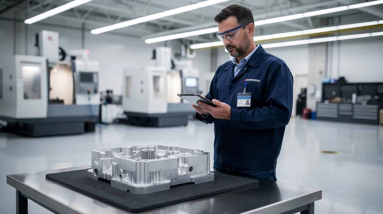
    An aerospace inspector is examining a machined component on a clean production floor while using a tablet, highlighting the importance of quality management systems and the effective CAPA (Corrective and Preventive Actions) process in ensuring regulatory compliance and continuous improvement in aerospace manufacturing.

    What is CAPA in Aerospace Manufacturing and MRO?

    CAPA stands for Corrective and Preventive Action. In practice, it means corrective and preventive actions taken through a formal, evidence based workflow. Corrective actions address known quality problems and prevent recurrence. Preventive actions address related risks before they become quality defects, escapes, or safety events.

    CAPA is familiar in medical devices, medical device manufacturing, and the way medical device companies manage quality system obligations under federal regulations. Medical device manufacturers often face strong regulatory scrutiny around CAPA documentation, root cause determination, and effectiveness checks. Aerospace has a different operating environment, but the expectation is similar: a capa process must be traceable, risk based, and supported by evidence.

    In aerospace production and MRO, CAPA sits inside the quality management system. It connects nonconformance reports, MRB decisions, internal audits, supplier issues, customer escapes, service difficulty signals, and field events into a closed loop. It is not just a qms capa record. It is the mechanism for proving that the production process, maintenance process, or supplier process has been brought back under control.

    AS9100D Clause 10.2 expects organizations to react to nonconformities, determine root cause, consider whether similar nonconformities exist, implement corrective actions, and evaluate effectiveness. FAA and EASA regulatory requirements, NADCAP special process expectations, and customer quality clauses all point toward the same operating truth: an effective capa system must produce records that show what happened, why it happened, what changed, and whether the change worked. Guidance on AS9100D nonconformity and corrective action requirements is summarized by AS9100 Store.

    Connect981 provides the digital backbone for this work across factories, suppliers, and MRO facilities. Instead of tracking a capa plan through spreadsheets, email threads, local folders, and disconnected quality systems, teams can link defects, inspection evidence, owners, action plans, change control, and closure evidence in one shared workflow.

    When Should a CAPA Be Opened in Aerospace Operations?

    A CAPA should be opened when the evidence points beyond a single defect and toward systemic issues, repeat risk, regulatory impact, or significant safety and airworthiness concern. CAPA does not begin automatically every time an NCR is written. A one off nonconformance can often be handled through NCR, MRB disposition, containment, and correction.

    The decision changes when the same type of problem repeats, when a single event has high consequence, or when an audit finding shows a weakness in the quality management process. In those cases, a corrective action plan is needed because the organization must understand root cause and change the system, not just fix the affected part.

    Under using CAPA hides systemic risk. Overusing CAPA creates noise, delays, and long backlogs that prevent the team from focusing on high risk issues. The best capa procedures use risk based prioritization. They define when the CAPA threshold has been met, who approves the decision, what evidence is needed, and how capa outcomes will be measured.

    Connect981 supports this decision by reading across NCRs, defects, rework, supplier records, audit findings, and process data. The platform can surface capa trends and AI assisted root cause signals so quality leaders can see whether an issue is isolated or part of a wider pattern.

    Trigger Logic: Clear Criteria for Opening a CAPA

    Aerospace organizations should document CAPA trigger logic in their procedures and configure it into the capa system. The decision should not depend on who happens to be reviewing the issue that day. It should be consistent, auditable, and aligned with regulatory expectations.

    Common CAPA triggers include:

    • Repeated nonconformances on the same part family, feature, process, work center, tool, or supplier within a defined period. A practical threshold is three similar NCRs within 90 days, although each organization should set criteria based on its own processes and risk profile.
    • A serious quality escape affecting delivered aircraft, flight hardware, maintenance release, or customer safety. Structural fastener torque issues discovered after delivery should trigger CAPA immediately.
    • Internal audits, AS9100 audits, NADCAP audits, FAA or EASA findings, or customer audits that identify systemic weakness or repeated minor findings in the same area.
    • A high Risk Priority Number from FMEA, a severe risk assessment outcome, or risk analysis showing that even a single occurrence could affect airworthiness, compliance, or mission reliability.
    • Supplier quality problems involving safety critical parts, long lead components, counterfeit risk, traceability gaps, or repeated documentation failures.
    • Customer feedback showing recurring escapes, late corrective measures, or dissatisfaction tied to the same process weakness.
    • Negative trend data in scrap, rework, inspection failures, test failures, MRO turnaround delays, or supplier controls.

    A CAPA trigger does not mean the answer is already known. It means the organization has enough evidence to justify a thorough investigation. In Connect981, these criteria can be built into configurable workflows so recurring defects, supplier performance drops, or high risk issues are flagged before they become audit findings or customer escapes.

    Examples: When Immediate Correction Is Enough vs. When CAPA Is Required

    A single routing sheet error may not justify CAPA. If one work order has an incorrect router code, the affected record can be corrected, the lot can be reviewed, and the operator or planner can be briefed. If there is no trend, no safety impact, and no evidence of a broken planning process, an NCR and correction may be enough.

    A recurring torque verification gap is different. If three work orders for the same part family show missing torque verification on critical structural fasteners, the issue has moved beyond correction. The capa investigation should review work instructions, tooling, inspection points, training, human factors, and whether the router allows the operation to be skipped.

    Supplier labeling follows the same logic. One mislabeled shipment of non flight hardware may be handled through MRB, receiving inspection, and supplier notification. Multiple mislabels from the same supplier over two months point to supplier process weakness. That requires CAPA, supplier corrective actions, and likely a preventive action plan covering similar part families or packaging flows.

    A field event can trigger CAPA without waiting for recurrence. If an aircraft or engine assembly shows a structural issue after delivery, the organization should open CAPA based on risk, not count. Connect981 helps by showing recurrence across shops, suppliers, programs, and MRO stations, giving quality teams the evidence to justify escalation.

    How CAPA Differs from NCR, MRB, and Immediate Containment

    CAPA is often confused with NCR, MRB, and containment because all four may appear in the same quality event. They are connected, but they do different work.

    • Nonconformance Report, or NCR: The NCR is the initial record of a defect or deviation on a part, assembly, process, document, or maintenance task. It often applies to a single work order, batch, serial number, or inspection record.
    • Material Review Board, or MRB: MRB is the engineering and quality decision process for dispositioning nonconforming product. Typical dispositions include use as is, repair, rework, scrap, or return to supplier. MRB decides the fate of product. It does not, by itself, solve the process failure.
    • Immediate containment or correction: Containment protects the customer, the aircraft, and production flow while the facts are being established. Examples include quarantine, stop use, stop shipment, added inspection, temporary rework, and suspect lot review.
    • CAPA: CAPA sits above NCR and MRB. It is triggered when data from those processes show deeper process failure, repeat risk, regulatory compliance exposure, or safety concern.

    The distinction matters. Containment may stop the bleeding, but it does not prove the root cause has been removed. MRB may release or scrap hardware, but it does not verify effectiveness of a process change. CAPA is the closed loop record that shows root cause, corrective or preventive actions, implementation evidence, and capa effectiveness.

    Connect981 links NCRs, MRB decisions, containment tasks, and CAPA records so teams can see the full chain from first defect through confirmed root cause and long term fix. The result is better traceability and fewer gaps during regulatory inspections.

    Practical Process Flow: From Deviation to CAPA

    A practical process keeps the handoffs clear:

    • Defect or deviation is logged as an NCR with part number, serial number, operation, work order, inspector, and evidence.
    • MRB reviews the affected product and determines disposition, such as rework, repair, scrap, use as is, or return to supplier.
    • Immediate containment protects the customer and production flow. Suspect inventory may be quarantined, shipments paused, or inspection expanded.
    • Quality performs trend review and risk assessment using NCR history, process data, audit findings, supplier records, and customer feedback.
    • CAPA is opened if trigger criteria are met. The capa owner is assigned, scope is defined, and the capa form becomes the umbrella record.
    • The investigation aggregates NCRs, MRB records, inspection results, supplier inputs, engineering analysis, and production evidence.
    • Corrective actions and preventive measures are implemented, verified, monitored, and reviewed for closure.

    In Connect981, this flow is modeled as linked digital workflows. Teams avoid duplicate data entry, evidence remains connected to the original event, and the audit trail is built as the work happens.

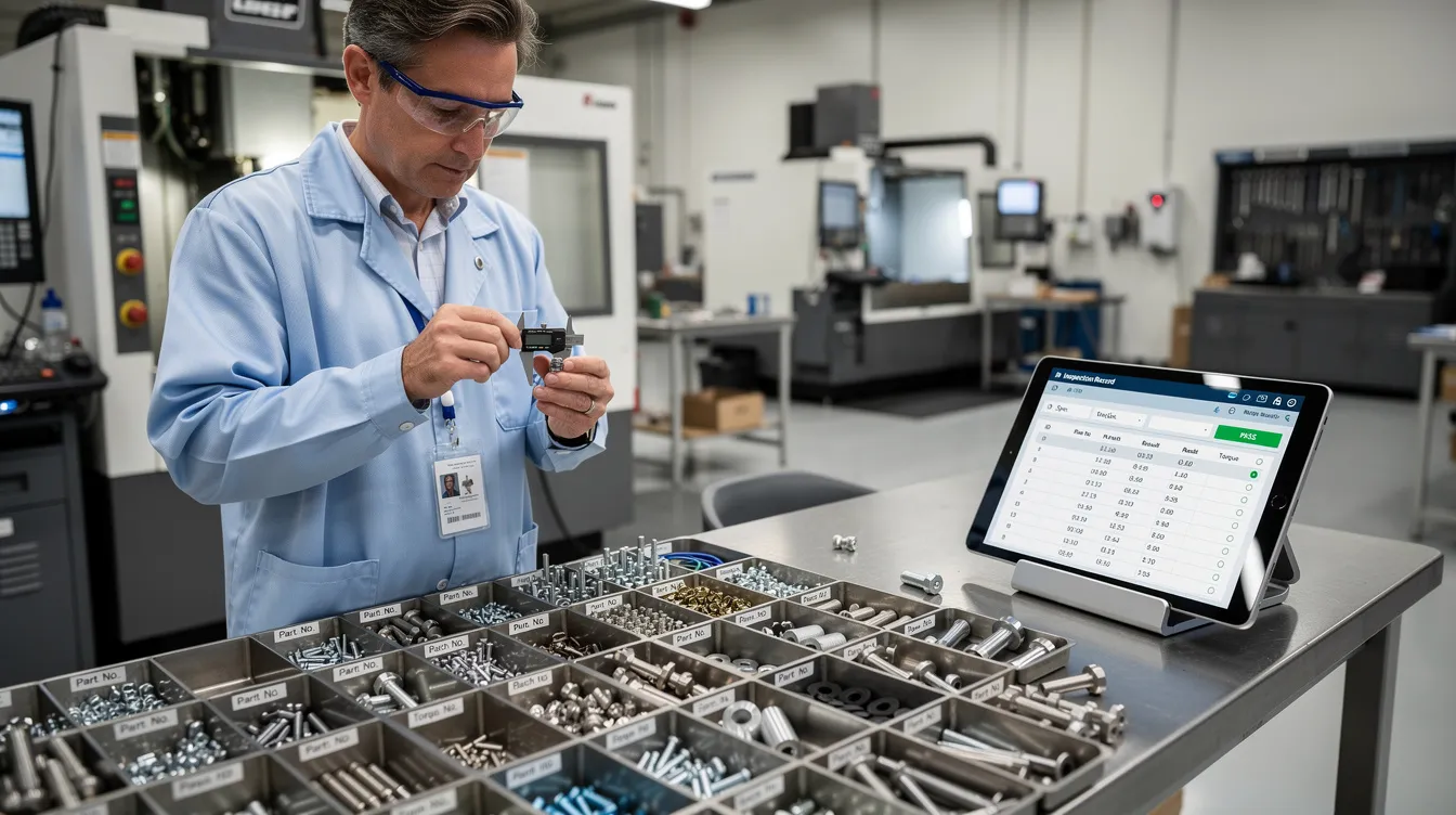
    A quality engineer is inspecting aerospace fasteners at a workstation, while digital records are displayed on a tablet, highlighting the importance of a quality management system in ensuring regulatory compliance and effective corrective actions. The scene emphasizes the role of continuous improvement and thorough investigation in the aerospace industry.

    The CAPA Investigation: Root Cause, Evidence, and Action Planning

    A real capa investigation starts with a clear problem statement. The statement should describe what failed, where it failed, when it was found, how many units were affected, which requirements were missed, and why the issue matters. Vague language creates weak investigations. A well documented CAPA file begins with operational facts.

    The investigation then defines scope. That includes affected parts, programs, suppliers, work centers, shifts, tools, routers, inspection points, MRO tasks, and potentially delivered product. The team should also evaluate whether similar nonconformities exist elsewhere. AS9100D expects this broader check, not only a review of the visible defect.

    Aerospace CAPA cannot stop at “operator error.” Human factors matter, but they must be examined in context. The team should review instruction clarity, training records, tooling condition, calibration, access to current revisions, environmental conditions, supervision, inspection plans, supplier controls, and change control history. EASA Part 145 environments also expect root cause and contributing factor analysis for findings, as summarized in industry guidance on aviation maintenance root cause analysis.

    Each CAPA should document the problem statement, scope, data sources, root cause analysis, corrective actions, preventive actions, and effectiveness verification plan. Connect981 keeps photos, NCRs, SPC charts, supplier emails, FAI reports, calibration logs, and revised work instructions linked to the CAPA record for fast retrieval during audits.

    Root Cause Analysis in Aerospace CAPA

    Root cause analysis is a disciplined method for separating symptoms from causes. It should be practical, not theatrical. The goal is root cause determination that can be tested against evidence and translated into corrective measures.

    Useful methods include:

    • 5 Whys for straightforward process breakdowns, such as a skipped verification step.
    • Fishbone or Ishikawa analysis for issues with multiple contributing factors, such as plating defects involving chemistry, tooling, handling, and inspection.
    • fault tree analysis for safety critical failures where event logic and failure paths must be understood.
    • FMEA review when the failure mode was known but risk management controls did not prevent occurrence or detection failure.
    • Process mapping when handoffs between planning, stores, inspection, MRO, or supplier teams are unclear.

    CAPA should involve cross functional teams when the issue crosses boundaries. A cross functional team may include quality, manufacturing engineering, design engineering, production, MRO leads, supply chain, supplier quality, and program management. In high consequence cases, organizations should involve cross functional teams early so the investigation does not optimize one department while missing the system failure.

    Connect981 can support RCA by surfacing similar events, defect history, supplier patterns, and prior capa actions. AI assisted root cause suggestions can point teams toward likely contributing factors, but the decision remains with engineering and quality. The confirmed root cause must be supported by evidence.

    Evidence Requirements: What Belongs in CAPA Documentation

    Good capa documentation tells a coherent story. An auditor, customer representative, or new quality manager should be able to understand what happened, why it happened, what changed, and how the organization verified the result.

    Typical evidence includes:

    • NCR history and defect records.
    • Scrap, rework, and repair trends before and after the event.
    • Inspection results, SPC charts, capability studies, and test data.
    • Photos, microscopy, measurement reports, or lab results showing the defect.
    • Calibration records, tool maintenance logs, and gage records.
    • Training records, qualification sign offs, and skill matrix updates.
    • Revised digital work instructions, routers, inspection plans, and control plans.
    • Change control approvals, ECOs, drawing updates, software revisions, or CNC program validation.
    • First Article Inspection records when the process or configuration changed.
    • Supplier corrective action reports, supplier audits, and receiving inspection evidence.
    • Risk assessment, risk analysis, and FMEA updates.
    • CAPA review notes, approvals, and management review inputs when appropriate.

    Each root cause should have supporting evidence. Each corrective action and preventive action capa item should also have proof that it was implemented. If the fix was an updated torque specification, the CAPA file should link to the approved specification, revised router, updated work instruction, and evidence that the station is using the current revision.

    Connect981 acts as a single evidence repository across ERP, MES, PLM, QMS, and supplier data. This matters because CAPA evidence often lives in fragments. One piece is in email, another in a file share, another in a supplier portal, and another on the shopfloor. Fragmented evidence creates audit risk even when the team did the right work.

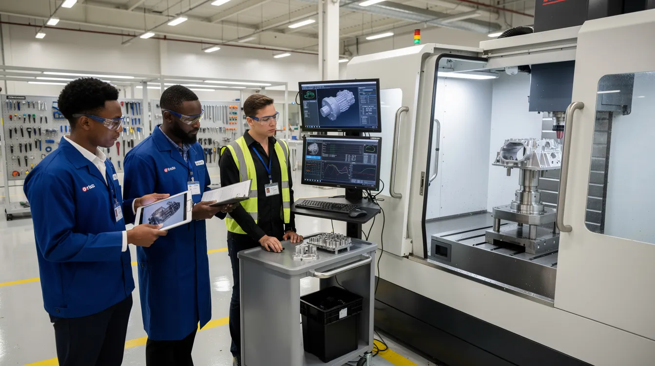
    A cross-functional aerospace quality team is reviewing component inspection results beside a production cell, focusing on implementing corrective and preventive actions as part of their quality management system. They are engaged in root cause analysis to ensure continuous improvement and prevent recurrence of quality defects in the manufacturing process.

    Building the CAPA Action Plan

    The capa plan translates root cause findings into specific action plans. It should separate correction from corrective action. Correction fixes the affected part or record. Corrective action changes the system so the issue does not recur. A preventive action plan extends the lesson to similar risks elsewhere.

    An aerospace CAPA action plan may include:

    • Process changes to routing, inspection sequence, traveler logic, or MRO task flow.
    • Procedure updates and revised digital work instructions.
    • Tooling changes, fixture improvements, calibration frequency changes, or gage updates.
    • Training tied to the revised process, not generic retraining.
    • Supplier development, supplier audits, or updated purchase order quality clauses.
    • Design changes, ECOs, configuration updates, or FAI requirements.
    • Additional controls for detection, such as automated verification, required signoffs, or inspection hold points.

    Every action should have an owner, due date, risk priority, required evidence, and acceptance criteria. The capa owner should not be left to chase status manually through email. Capa management works best when ownership, escalation, and evidence expectations are visible from the start.

    Connect981 provides configurable CAPA forms with action tables, owner assignment, e signatures, due dates, escalation logic, and links to downstream change control and validation activities. This supports implementing corrective actions without losing the connection between the root cause and the work being done.

    Effective CAPA Closure: What “Done” Really Looks Like

    Effective capa closure is not the point where tasks are checked off. It is the point where evidence shows the issue is controlled and unlikely to recur within defined risk limits. That is the difference between activity and control.

    A strong capa program defines closure criteria before closure begins. For example, the organization may require three consecutive production lots with zero repeat defects, 90 days without a similar NCR, a successful internal audit of the revised process, or verified supplier performance after corrective action. The criteria should match the severity and risk of the issue.

    Cosmetic closure is a common failure. A document is updated, a training record is signed, and the CAPA is closed before the production process proves stability. That approach does not satisfy regulatory expectations. It also fails operations because recurrence returns the same problem to the same people weeks later.

    Aerospace teams should use plan do check act thinking. Plan the CAPA, do the implementation, check performance against evidence, and act again if the data shows the fix did not hold. This is where capa effectiveness is proven. Connect981 can automate effectiveness tracking using real production and inspection data, then prompt the capa owner when enough evidence is available for closure review.

    Closure Evidence: Proving the CAPA Worked

    Closure evidence should prove that the action was implemented and that it worked. Auditors and OEM customers are not looking for a clean form. They are looking for evidence of a controlled process.

    Useful closure evidence includes:

    • Before and after trend charts showing reduced defect rate, scrap, rework, or escapes.
    • Zero repeat NCRs for the same issue over a defined time period or production quantity.
    • Successful FAI after a process, tooling, or configuration change.
    • Audit reports confirming that operators are using the revised procedure or work instruction.
    • Approved ECOs, updated drawings, released routers, revised inspection plans, and current digital work instructions.
    • Validated CNC, test rig, inspection, or software program changes where applicable.
    • Training completion records tied to the exact revised process.
    • Supplier performance records showing the same defect has not recurred.
    • Updated FMEA, risk controls, control plans, or inspection frequency.
    • Formal capa review sign off by the quality manager, CAPA board, or authorized approver.

    The CAPA review should confirm that the root cause logic is sound, the risk assessment remains valid, the actions match the cause, and the effectiveness data is sufficient. If the evidence is weak, the CAPA should remain open. If recurrence appears, the team should reopen the investigation or launch a new CAPA with the prior failure included in the analysis.

    Connect981 presents closure packets and dashboards that show timelines, action status, evidence links, trend plots, and approval history. This helps quality leaders verify effectiveness without rebuilding the story from scattered records.

    Integrating CAPA with Change Control, Quality Management, and Suppliers

    CAPA does not operate alone. It is part of quality management, risk management, supplier management, configuration control, and production execution. Many capa actions require formal change control because they affect routers, work instructions, inspection plans, tooling, software, drawings, or maintenance procedures.

    That integration is where many organizations struggle. A CAPA may require an updated work instruction, but the change is released only in a document system and never reaches the station. A supplier may submit a response, but receiving inspection does not change its sampling plan. An engineering change may be approved, but the FAI requirement is missed. These are not individual failures. They are workflow gaps.

    CAPA should connect to:

    • Internal audits and audit finding closure.
    • FAI and production readiness.
    • Configuration management and engineering change control.
    • MRO maintenance records and parts history.
    • Supplier portals, supplier corrective actions, and procurement workflows.
    • Training and qualification management.
    • Management review, especially for repeated or high severity capa trends.

    Connect981 links CAPA to change control workflows, supplier collaboration, and real time shopfloor execution. Approved changes can be pushed to the right workstations, suppliers, and inspection points with revision control. The organization can then show not only that the CAPA was approved, but that the approved process reached the people doing the work.

    Digital CAPA Systems in Aerospace: From Paper to Connected Workflows

    Paper and spreadsheet based CAPA tracking can work for a small volume of simple issues. It breaks down when operations span multiple sites, suppliers, product lines, and regulatory obligations. The problem is not just administration. The problem is weak data continuity.

    An effective capa system gives teams a single source of truth for CAPA documentation, owners, due dates, evidence, approvals, and closure status. It also supports automated reminders, escalations, consistent templates, electronic signatures, and audit ready traceability. In practice, this reduces time spent searching for records and increases time spent solving the actual problem.

    A connected digital system should support:

    • Linked NCR, MRB, containment, CAPA, and closure records.
    • Real time dashboards for open actions, aging, risk level, and overdue items.
    • Cross site capa trends and supplier performance visibility.
    • Configurable capa procedures that reflect the organization’s quality system.
    • AI assisted root cause analysis and production quality insights.
    • Integration with ERP, MES, PLM, QMS, supplier portals, and shopfloor execution.
    • Evidence capture from photos, inspections, calibration records, training, and change approvals.

    Technology does not replace judgment. It helps the organization make good judgment repeatable. Connect981 is built for aerospace manufacturing and MRO teams that need CAPA connected to real work: digital work instructions, quality checks, supplier collaboration, traceability, routing, and compliance records.

    For aerospace manufacturers and MRO providers looking to standardize CAPA, reduce regulatory compliance risk, and close the loop from defect to verified improvement, Connect981 provides a practical path. Request a demo to see how an integrated CAPA workflow can connect NCRs, MRB decisions, root cause analysis, change control, supplier actions, and effectiveness verification in one operational layer.

  • Andon System Manufacturing: From Cords and Lights to Digital Escalation Workflows

    Andon System Manufacturing: From Cords and Lights to Digital Escalation Workflows

    Key Takeaways

    • An andon system is a structured escalation process, not just a light, board, or andon cord.
    • Andon in lean manufacturing still matters because it creates faster response, fewer defects, less downtime, and better visibility.
    • Modern digital andon systems connect alerts to corrective actions, root cause analysis, dashboards, and continuous improvement.
    • Connect 981 supports andon-style workflows inside a broader aerospace and MRO operations platform, not as a standalone andon light system.

    Introduction: Why Andon System Manufacturing Still Matters in 2026

    In 2026, many production problems still start small. A machinist sees a dimension drifting on an aerospace component. An electronics operator detects a missing connector before test. An MRO technician opens an engine module and finds the routing sheet does not match the installed configuration. If the issue is not surfaced quickly, hours of rework, scrap, schedule disruption, and audit exposure follow.

    Unplanned downtime commonly consumes 5 to 20 percent of productive capacity in manufacturing, according to Monitory.ai research on downtime cost. In regulated industries like aerospace, the cost is not only lost production time. A single escaped defect can trigger NCRs, MRB review, customer notification, and late delivery penalties.

    That is why andon system manufacturing remains relevant in high-mix, high-variance environments such as aerospace structures, avionics, precision machining, and MRO. This article treats the andon system as a structured escalation mechanism: signal, ownership, response, resolution, and learning.

    Traditional Andon systems typically rely on physical components such as pull cords, lights, and manual boards to signal issues, while digital Andon systems integrate with software and IoT technologies for real-time monitoring and alerts. The best implementations connect MES, ERP, quality records, supplier workflows, and continuous improvement efforts.

    A factory operator is using a tablet beside an aircraft assembly fixture, actively engaging in the production process while utilizing a digital andon system for quality control and operational excellence. The setup highlights the integration of modern andon systems in lean manufacturing, enhancing problem detection and rapid response capabilities on the production floor.

    What Is an Andon System in Manufacturing?

    An andon system is a visual and audible alert and escalation mechanism that surfaces abnormalities in real time. The japanese word “andon” originally referred to a lantern, which is why the concept became closely associated with visual management.

    Its roots are in lean manufacturing and the toyota production system, especially jidoka: build in quality and stop to fix when an abnormality occurs. In Toyota’s production system, the Andon cord allows any assembly employee to pause production when quality issues arise, ensuring defects do not propagate down the line.

    A good andon process replaces shouting, radios, sticky notes, and tribal knowledge with standardized andon signals. Operators, line workers, team leader roles, maintenance technicians, quality engineers, logistics, safety, engineering, and production control all know what happens next.

    The andon system works through a simple flow: problem detection, andon alert, owner assignment, corrective actions, closure, and data logging. The primary benefits of an Andon system include reduced downtime, empowered workers, higher quality control, and data-driven process improvements.

    How an Andon System Works on the Shop Floor

    An Andon system operates through a precise process flow designed for rapid response, allowing operators to signal issues immediately when they occur. Andon systems enable immediate problem detection, allowing workers to quickly identify and report issues without leaving their workstations, which results in reduced downtime and improved productivity.

    A trigger may be an andon cord pull, push button, HMI soft button, barcode scan, QR scan, automatic andon from sensors or PLCs, or software-triggered digital alerts. In a mature system, the andon alert includes location, issue type, severity, timing, product, and work order.

    In the first five minutes, the team acknowledges the alert notification, triages at the station, decides whether to stop production, and applies containment or a temporary countermeasure. If the line stops, restart criteria should be explicit. Every event should be timestamped, categorized, and tied to a job, serial, or work order.

    Core Components: Cords, Lights, Boards, and Digital Andon

    The classic Andon system consists of three primary components: the Andon cord, Andon light, and Andon board, which work together to signal issues on the production floor. Andon systems typically consist of three primary components: an Andon cord, an Andon light, and an Andon board, which work together to alert team members about production issues.

    Traditional Andon Cords and Fixed-Position Stop

    Traditional andon on final assembly lines often used an overhead andon board and overhead pull cord. The Andon cord is typically located overhead on the assembly line and can be pulled by operators to signal that assistance is needed due to a problem identified in the production process.

    When an operator pulls the cord on a manufacturing line, a timed response window starts. If the issue is not resolved, the product stops at a predefined station. In a fuselage section, for example, mis-torqued fasteners must be corrected before the body moves to the next dock. This balances flow protection with product quality protection.

    Andon Lights, Buzzers, and Local Signals

    Stack lights, buzzers, audio alerts, and visual cues provide immediate local feedback. Andon lights use a color-coded system to indicate the status of production: green for normal operation, yellow for a minor issue that needs attention, and red for a stop condition requiring immediate investigation.

    The Andon light system uses color coding to indicate different statuses: green for normal operation, yellow for minor issues needing attention, and red for serious problems requiring immediate action. Color-coded lights and auditory tones are typically used in Andon systems to denote production status and operational bottlenecks.

    Local signals are useful, but support teams may miss them in large plants, noisy areas, or dense layouts. A light alone does not prove who responded, when they arrived, or whether the root cause was removed.

    Andon Boards and Plant-Wide Visibility

    Andon boards serve as centralized visual control centers that display the status of production lines, allowing supervisors and team members to quickly assess operational conditions and respond accordingly. Andon boards serve as centralized visual control centers that display the status of production lines, allowing supervisors and team members to monitor operations at a glance.

    Traditional andon boards used physical lights, tags, or scoreboards. Digital boards now show line status, downtime reasons, response timers, production targets, production metrics, and open escalation paths across the plant floor.

    From Physical Andon to Digital Andon Systems

    A digital andon system combines physical signals with andon software, mobile notifications, IIoT sensors, and role-based workflows. Digital Andon systems enhance the traditional approach by providing automated alerts, real-time data integration, and customizable dashboards, which allow for faster response times and better tracking of production issues.

    In modern Andon systems, digital boards can integrate with factory systems to provide real-time data visualization, showing key performance indicators and alerts for immediate action. Digital Andon systems enhance traditional setups by integrating with other manufacturing software, providing real-time data visualization and automated alerts to improve response times.

    Why Andon Matters in Lean Manufacturing and Aerospace Operations

    Andon systems are integral to Lean manufacturing as they provide immediate visual alerts to operators and management about production issues, enabling quick responses to prevent defects from propagating down the line. As a lean tool, andon supports flow, respect for people, quality assurance, and the lean principle of stopping to fix.

    The implementation of Andon systems supports the Lean principle of continuous improvement (Kaizen) by allowing workers to identify and address problems as they occur, thus reducing waste and enhancing product quality. Andon systems support continuous improvement (Kaizen) by helping identify frequent stumbling blocks in the production process, which can lead to targeted improvements.

    Andon systems help minimize defects by catching errors at the source, saving time, reducing material waste, and lowering rework costs. By addressing issues as they occur, Andon systems help ensure that resources are used efficiently and only high-quality products continue through the production line, leading to scrap reduction.

    Andon systems empower employees by allowing them to stop production when they detect a quality issue, fostering a culture of accountability and teamwork focused on quality and efficiency. Implementing Andon systems empowers employees by allowing them to stop the production line if they detect a quality issue, promoting a culture of quality and accountability.

    For aerospace and MRO, this matters because traceability, AS9100, FAA, EASA, ITAR, configuration control, and quality standards create a higher cost of late detection. Andon systems provide real-time visibility into the manufacturing process, enabling teams to identify and resolve floor abnormalities before they escalate.

    Traditional Andon vs. Digital Andon: What’s Really Different?

    Most plants do not choose between physical and digital. They blend both. The real shift is from “signal only” to “signal plus response management and learning.”

    Traditional Andon: Fast Signal, Limited Follow-Through

    While traditional Andon systems provide immediate visual signals, they often lack the ability to track response times and issue resolution, whereas digital Andon systems can log incidents, assign tasks, and escalate alerts automatically.

    A torque wrench failure may trigger an andon signal. Maintenance arrives late, the tool is swapped, and production resumes. If duration, cause, and corrective actions are not recorded, the same issue repeats across shifts.

    Digital Andon: From Alert to Resolution Management

    Digital systems convert an alert into a structured event with line, station, product, shift, category, severity, and timestamps. Digitally driven Andon systems can track downtime patterns and recurring issues, providing actionable data for long-term process optimization.

    Modern Andon systems log the frequency and duration of stops to help managers track long-term bottlenecks. If no one acknowledges an alert within the defined time, escalation moves to supervisors, value stream managers, or plant leadership.

    Hybrid Approaches: Lights on the Line, Software in the Background

    A strong hybrid approach keeps the operator interface simple. A button press at a CNC cell can change stack lights, log the event, and notify maintenance through mobile notifications. This preserves quick response while adding traceability, accountability, and data for reducing waste.

    What Problems Does an Andon System Signal? Practical Shopfloor Examples

    Andon alerts should focus on problems that affect flow, safety, quality, delivery, or compliance. Common categories include machine downtime, quality issues, material shortage, supplier part issue, tooling, calibration, documentation, safety concern, and production bottleneck.

    Machine Downtime and Equipment Failures

    A CNC spindle alarm, hydraulic leak, or oven temperature deviation should trigger an andon alert. Maintenance technicians receive the alert, line status changes, and the timer starts. Capture machine ID, fault code, duration, spare parts used, root cause, and corrective actions.

    Quality Defects and Escaped Issues

    A dimensional nonconformance or wiring error should route to quality engineers. The area may contain suspect product, pause the station, or stop production if the defect could move downstream. Link the event to NCR, MRB, 8D, lot, and serial records.

    Material Shortages and Supplier Part Issues

    If a kitting area lacks a bracket or a supplier seal fails incoming inspection, the alert should go to materials, procurement, and planning. Capture part number, supplier, required quantity, PO, work order, and schedule impact.

    Tooling, Fixtures, and Calibration Problems

    A worn cutting tool, fixture misalignment, or expired gauge can create quiet quality drift. The andon system gives operators permission to call for help before bad parts accumulate. Tracking these events improves tool change intervals, poka-yoke, and standard work.

    Documentation, Work Instructions, and Missing Information

    Outdated drawings, unclear digital work instructions, or missing customer addenda are legitimate andon events. Operators should not build to guesswork. Digital andon connects the issue to the exact work order, revision, operation, and owner.

    Safety Concerns and Near Misses

    Coolant on a walkway, missing guarding, or incorrect PPE should trigger stricter rules. Safety alerts often require immediate stop, EHS involvement, photos, contributing factors, and preventive action.

    Production Bottlenecks and Operator Assistance

    Not every alert means the line stops. Assistance calls help team leaders rebalance labor, support training, and identify unstable work. Separate assistance KPIs from hard stops so line workers keep raising issues when problems arise.

    Issue Categories, Response Rules, and Accountability

    Categorization turns lights and noise into a management system. Plants should define stable categories such as quality, machine, material, safety, documentation, methods, and staffing.

    Each category needs a default owner, response expectation, and restart rule. Quality may require containment. Machine faults may require lockout or maintenance triage. Supplier problems may require buyer escalation. Digital systems can enforce role-based ownership so issues arise, move, and close with named accountability.

    Andon as a Continuous Improvement Engine, Not Just an Alarm

    The value of andon is not only faster firefighting. It is the learning loop. Frequency, duration, category, root cause, area, and shift data feed Pareto charts, A3 reviews, kaizen events, and continuous improvement priorities.

    Andon systems foster better communication between workers and management, ensuring that alerts can be acted upon swiftly, which enhances overall operational efficiency. Weekly reviews can expose chronic supplier shortages, repeated sensor failures, unclear work instructions, and gaps in robust processes.

    Common Andon Implementation Mistakes (and How to Avoid Them)

    Many plants install lights and cords but never achieve operational excellence because the process is weak. Common mistakes include treating andon as hardware only, unclear rules, slow response, blame culture, excessive categories, and poor data capture.

    3M and Caterpillar utilize button-based Andon systems where operators can signal issues, prompting immediate attention from team leaders to resolve problems quickly. Amazon employs a “Virtual Andon Cord” in its customer service operations, allowing representatives to trigger alerts for significant product issues, potentially halting shipments until the root cause is addressed. In healthcare, Andon principles are applied to improve patient safety, such as using lights on Code Blue carts to signal daily checks and alarms on infusion pumps to alert staff about potential issues.

    Slow Response Times and Missing Escalation

    If no one responds, operators stop using the system. Define expectations, such as two to three minutes for acknowledgement and a severity-based target for first action. Use andon boards or dashboards to show open alerts and timers.

    Unclear Ownership and Fragmented Follow-Up

    “Maintenance will handle it” is not ownership. Assign a role or named owner for each alert, require handoffs, and prevent closure without verified corrective actions.

    Weak Data Capture and Inconsistent Classification

    Paper logs and retrospective spreadsheets are late, incomplete, and hard to analyze. Use simple digital forms with picklists, photos, cause codes, and periodic data quality audits.

    Designing an Andon Workflow: Practical Checklist

    Use this checklist when implementing andon or upgrading a lean manufacturing system.

    Checklist Items: From Trigger to Trend Review

    • Who can trigger an andon alert? Operators, inspectors, maintenance, team leaders, and any person for safety or quality concerns.
    • How is the alert triggered? Andon cord, push button, stack light, tablet, HMI, QR code, sensor, PLC, or automatic andon.
    • What happens immediately? Acknowledge, triage, contain, decide whether the line stops, and communicate status.
    • Who owns the response? Assign default owners by category and escalation paths when the issue is not resolved.
    • What data is captured? Station, machine, product, batch, serial, shift, severity, timestamps, photos, root cause, and action.
    • How is the issue closed? Require verification, documented corrective actions, and restart approval when needed.
    • How are trends reviewed? Use weekly or monthly reviews of dashboards, production metrics, repeat issues, and top loss drivers.
    • How should rollout begin? Pilot one line or cell, refine with operators, then scale across the plant.

    A maintenance technician is inspecting a machine tool on the production floor, with a nearby signal light indicating the status of the andon system. This visual management tool helps alert operators to any quality control issues or abnormalities that may arise during the production process.

    Digital Andon Systems and Workflow-Based Escalation

    Modern andon systems increasingly sit inside broader digital operations platforms. The digital andon system integrates with MES, ERP, CMMS, QMS, PLM, and supplier systems to create a unified view of production, quality, and maintenance.

    In a high-tech electronics assembly line, an automatic Andon system uses sensors to detect assembly errors and equipment malfunctions, triggering visual alerts on digital dashboards and notifications to maintenance teams. This is where digital tools matter: alerts become tasks, approvals, and records instead of isolated messages.

    Andon Software Capabilities to Look For

    Look for configurable alert types, routing rules, multi-channel notifications, timed escalation, structured forms, photo uploads, links to work orders, links to defect records, audit logs, digital boards, OEE dashboards, and APIs. Configurability is critical because new products, regulations, and routings change faster than traditional IT projects.

    How Connect 981 Supports Andon-Style Escalation in Aerospace and MRO

    Connect 981 is a unified aerospace operations platform that can support andon-style escalation as part of broader production, quality, supplier, and MRO workflows. It is not an andon light system. It is an operations layer that connects alerts with work instructions, traceability, defects, supplier collaboration, and compliance records.

    From Andon Alert to Structured Workflow

    An operator or inspector can raise an alert from a tablet form tied to a work step. Connect 981 can route the event to quality, maintenance, methods, supply chain, or program teams based on line, category, customer, or severity. Status changes such as raised, acknowledged, blocked, resolved, and verified are timestamped.

    Connecting Andon to Work Instructions, Quality, and Traceability

    Connect 981 links events to digital work instructions, drawing revisions, inspection plans, serial numbers, lot numbers, and configuration records. This prevents a common failure mode: the alert lives in one system while the quality record, maintenance action, and supplier response live elsewhere.

    Cross-Factory and Supplier Visibility

    Aerospace primes and tier suppliers often need shared visibility when a supplier issue threatens schedule or conformity. Connect 981 can support cross-factory comparison of alert frequency, response times, issue types, and supplier nonconformance patterns.

    A group of aerospace technicians is gathered on a clean shop floor, closely reviewing a critical component as part of their quality control process. The environment reflects lean manufacturing principles, emphasizing operational excellence and continuous improvement efforts in their production line.

    Why Zero/Low-Code Matters for Andon Workflows

    Aerospace and MRO operations change frequently. New programs, customer requirements, inspection steps, and supplier rules require adaptable workflows. Connect 981’s zero and low-code workflow builder helps operations and CI teams adjust categories, forms, routing, and escalation without long custom development cycles.

    Conclusion: Build an Andon System That Turns Problems Into Progress

    An effective andon system is a structured escalation process that spans signal, alert, response, verification, and learning. Traditional cords, stack lights, and boards still have value, but they deliver more when connected to workflows, data capture, and accountability.

    The practical question is direct: are problems visible, are responses reliable, and does event data drive improvement? If not, the system is signaling, but it is not yet learning.

    Request a demo to see how Connect 981 turns shopfloor issues into structured workflows, traceable actions, and production visibility across aerospace manufacturing and MRO.

    FAQ

    How big should we start when implementing or upgrading an Andon system?

    Start with one production line, cell, or value stream. Use three to five categories, simple response rules, and a 60 to 90 day pilot. Include operators, maintenance, quality, and team leaders from day one.

    Do we need new hardware to move to a digital Andon system?

    Not always. Existing stack lights, buttons, PLC inputs, and HMIs can often connect through gateways or APIs. In many cases, the bigger change is process discipline, not hardware replacement.

    How do we prevent operators from overusing the Andon system and slowing production?

    Define severity levels and clear examples. A safety concern, quality risk, sustained equipment issue, or missing critical information should be raised early. Minor help calls should be tracked separately from hard stops.

    How does an Andon system fit with our existing MES or ERP?

    Andon complements MES and ERP by handling real-time exceptions around the execution data those systems manage. Platforms like Connect 981 can sit above existing systems as a unified operations layer.

    What metrics should we use to measure Andon system effectiveness?

    Track alerts by category, average response time, average resolution time, repeat issue rate, downtime minutes, scrap, rework, and production impact. Review these metrics in tiered meetings and CI reviews, not only on dashboards.
  • Value Stream

    Core meaning

    A **value stream** is the end-to-end sequence of activities and information flows required to deliver a product or service to a customer, from initial request or order through to delivery and payment.

    In industrial and manufacturing contexts, a value stream typically includes:

    – Material flow (raw material receipt, storage, processing, assembly, packaging, shipping)
    – Information flow (orders, schedules, specifications, quality data, approvals)
    – Supporting processes (maintenance, change control, documentation, release decisions)

    The value stream is considered at a system level, cutting across functions (e.g., planning, production, quality, logistics) rather than being limited to any single department or work center.

    Use in industrial and regulated environments

    Within manufacturing operations, a value stream commonly refers to the complete pathway for a defined product family or service, such as:

    – From sales order entry in an ERP system to finished goods shipment
    – From production planning through shop-floor execution, in-process testing, and batch release
    – From receipt and qualification of raw materials through conversion into intermediate and final products

    In regulated environments, the value stream also encompasses compliant handling of records, approvals, and traceability, including:

    – Electronic records captured by MES, LIMS, or quality systems
    – Review and approval workflows for deviations, change controls, or batch documentation
    – Data handoffs between OT systems (e.g., equipment, SCADA) and IT systems (e.g., ERP, QMS)

    Relationship to systems and data flows

    A value stream is independent of specific software tools, but it is often mapped using the underlying systems and interfaces, for example:

    – Customer order in ERP → production order in MES → equipment execution on the shop floor
    – In-process test results in LIMS or MES → quality review in QMS → release decision to ERP
    – Sensor and equipment data in OT systems → aggregated in operations intelligence platforms → used for performance and quality analysis

    The value stream view focuses on how these systems and manual steps contribute to delivering value to the customer, and how delays, rework, or unnecessary activities introduce waste.

    Boundaries and exclusions

    A value stream:

    – **Includes** all steps (value-adding and non–value-adding) that are required to deliver a defined product or service outcome
    – **Includes** both physical activities (processing, transporting, storing) and information activities (planning, scheduling, approving, recording)
    – **Extends** across organizational boundaries where those steps are necessary to fulfill the customer need (e.g., suppliers, contract manufacturers, logistics providers), when they are in scope of the analysis

    A value stream is **not**:

    – A single process step, work cell, or piece of equipment on its own
    – Limited to production; it can include order entry, design/engineering, purchasing, and post-delivery activities when relevant
    – A specific tool or document type; diagrams and maps are representations of the value stream, not the stream itself

    Common confusion and related terms

    Value stream is often confused with or used interchangeably with other concepts:

    – **Process**: A process is a set of activities that transforms inputs into outputs, often within one function or area. A value stream spans multiple processes and functions from end to end.
    – **Value chain**: Commonly used at a business or corporate strategy level to describe high-level activities (e.g., R&D, manufacturing, marketing). A value stream is typically narrower and focused on a specific product family or service delivery path.
    – **Production line**: Refers to physical equipment and operations used to make a product. The value stream includes the production line but also planning, quality, logistics, and supporting information flows.

    Being explicit about whether one is discussing a process, a production line, a value chain, or a value stream helps avoid misalignment when analyzing or improving operations.

    Site-context application

    On this site, value streams are frequently discussed in relation to:

    – **Lean manufacturing and continuous improvement**: Identifying waiting, rework, overproduction, excess movement, and other forms of waste across the end-to-end flow.
    – **MES/ERP and OT/IT integration**: Understanding where information originates, how it is transformed, and where gaps or manual workarounds occur along the value stream.
    – **Quality and compliance workflows**: Locating where quality decisions, record generation, and approvals sit in the value stream, and how they affect lead time and release.
    – **Operations intelligence and visibility**: Structuring dashboards and KPIs around value streams (e.g., order-to-cash, batch-to-release) rather than isolated equipment metrics.

    In practice, value streams provide the organizing lens for mapping, measuring, and discussing how industrial systems and workflows collectively deliver outcomes to internal or external customers.

  • Does ISO 27001 require DLP?

    ISO 27001 does not explicitly require a Data Loss Prevention (DLP) tool or any specific vendor solution. It is a risk-based management standard and is technology-agnostic. What it requires is that you identify risks to information confidentiality, integrity, and availability, then select and implement appropriate controls to treat those risks.

    What ISO 27001 actually requires

    ISO/IEC 27001 and its Annex A (aligned with ISO/IEC 27002) include a set of information security controls related to preventing unauthorized disclosure or exfiltration of information, for example:

    • Controls on information transfer (e.g., email, removable media, cloud collaboration).
    • Access control and least privilege around sensitive data.
    • Use of encryption where appropriate.
    • Monitoring and logging of critical systems and data access.
    • Data classification and handling rules for confidential and regulated data.

    DLP tooling can help satisfy several of these controls, but the standard does not say you must implement DLP as a named technology. You must show that the combination of policies, processes, and technical measures you use is suitable and effective for your risk profile.

    When DLP becomes effectively necessary

    In practice, many organizations find that some form of DLP or equivalent capability is hard to avoid when:

    • You handle a large volume of regulated or export-controlled technical data.
    • You have many external partners, contract manufacturers, or suppliers accessing shared information.
    • You rely on email, cloud storage, and collaboration tools across multiple sites and vendors.
    • Auditors or customers expect clear evidence of technical controls around data leakage, not just policy documents.

    Even then, you may meet the intent of ISO 27001 with a mix of other measures: network segmentation, strict access control, hardened endpoints, encryption, and strong governance around removable media and external data transfers. Whether this is acceptable depends on your documented risk assessment, your regulatory obligations, and the expectations of customers and auditors.

    Specific considerations for industrial and regulated environments

    On factory networks and OT systems, full DLP deployment is often constrained by:

    • Legacy systems and protocols: Older equipment and operating systems may not support agents or modern inspection methods.
    • Qualification and validation burden: Installing DLP agents or proxies on validated systems, MES, or historian servers can trigger revalidation, which is costly and time consuming.
    • Downtime risk: Enforcing content inspection on production traffic can introduce latency or instability, which is often unacceptable for critical automation.
    • Integration complexity: Mixed vendors, segmented networks, and site-specific architectures make consistent DLP coverage difficult.

    In these contexts, organizations often apply DLP or equivalent inspection at the enterprise IT layer (email, web gateways, end-user endpoints) and use different controls on OT networks:

    • Tight control of engineering workstations and data export paths (e.g., from MES, PLM, and QMS).
    • Whitelisted data transfer mechanisms between OT and IT (e.g., managed file transfer, data diodes).
    • Strict removable media processes, including logging, scanning, and approval workflows.
    • Segmentation and hardened jump hosts for vendor and remote access.

    ISO 27001 allows this kind of layered approach, as long as you can show that the chosen controls address the identified risks and are operated under change control and continuous improvement.

    How to decide if you need DLP for ISO 27001

    From a practical standpoint, the decision should follow your risk management and not just the desire to “check a box”:

    1. Perform or update your risk assessment: Identify where sensitive data lives (design files, NC programs, recipes, batch records, customer IP), who can access it, and how it moves inside and outside the organization.
    2. Identify leakage vectors: Email, cloud sharing, contractors, VPNs, removable media, remote support tools, and data exports from MES/PLM/ERP/QMS.
    3. Map existing controls: Access control, encryption, network segmentation, logging, supplier controls, and user training.
    4. Determine gaps: Where you cannot reasonably control or monitor data flows with current tooling and processes.
    5. Select proportional controls: DLP may be one of them, but you may also strengthen other controls where DLP is not feasible or would create unacceptable operational risk.

    If your risks around data exfiltration are high and you have no strong technical safeguards around information transfer, it will be hard to justify not implementing some DLP-like capability in your ISO 27001 risk treatment plan, even if you choose not to label it as a DLP product.

    Evidence expectations for ISO 27001 audits

    Auditors will not look for a specific DLP product name, but they will typically expect to see:

    • A documented risk assessment identifying data leakage risks.
    • Clear policies on information classification, handling, and transfer.
    • Technical and procedural controls that align with those policies.
    • Monitoring and incident response processes for potential data leaks.
    • Change control and validation practices for security changes on critical systems.

    If you use DLP, you should also show how it is configured, monitored, and governed. If you do not use DLP, you should be able to justify how your alternative controls are adequate and proportionate to risk, especially where regulated or export-controlled data is involved.

    In summary, ISO 27001 does not require DLP by name. It requires you to understand and control data leakage risks. In complex, regulated manufacturing environments with long-lived systems, that usually means combining selective DLP deployment in IT domains with other compensating controls and robust governance around sensitive technical data.

  • How do we avoid generating too many alerts for operators?

    Why alert overload happens in regulated manufacturing environments

    Alert overload usually emerges when notifications are added incrementally without a coherent design or ownership model. Different teams (IT, controls, quality, maintenance) create alerts for their own risks, but operators receive them all mixed together with little differentiation in importance. In brownfield plants, new alerts often sit on top of legacy SCADA, DCS, MES, and QMS notifications, amplifying noise from systems that were never designed to work together. Over time, operators learn to click through popups and ignore banners, which quietly undermines the very controls auditors expect to be effective. In regulated settings, this is especially risky because you can end up with formal procedures that assume alerts are acted on, while real behavior is to bypass or acknowledge them without response.

    Treat alerts as engineered, versioned objects

    To avoid generating too many alerts, treat each alert definition like a controlled configuration item, not a convenience notification. An alert should have a defined owner, a clear purpose, specified data source, thresholds, expected operator action, and escalation rules. Changes to alerts (new conditions, logic tweaks, routing changes) should go through formal change control and, where appropriate, re-validation or at least documented impact assessment. This slows down random alert creation but improves signal quality and operator trust. In aerospace-grade and similar environments, this model fits better with existing qualification and validation expectations than ad hoc alert tuning.

    Define severity, audience, and required action up front

    A practical way to reduce alert fatigue is to classify alerts by severity and audience before implementation. For each proposed alert, ask what the operator must do within what time, and what happens if nothing is done. High-severity alerts should be rare, clearly distinguishable, and directly tied to safety, product integrity, or regulatory impact. Lower-severity conditions may belong in dashboards, periodic reports, or maintenance backlogs rather than as real-time operator alerts. By formally deciding who needs to see which severity levels, you avoid routing every condition to the same overburdened operator console.

    Tune thresholds and logic using real plant data

    Overly sensitive thresholds and simplistic logic are major sources of unnecessary alerts. Static trigger points copied from vendor manuals or design assumptions often ignore actual process capability, measurement noise, and normal transients. Use historical data and process knowledge to set alert thresholds that distinguish real deviations from expected variability. Where possible, incorporate simple filtering (e.g., persistence over time, hysteresis, deadbands) so that brief spikes, communication glitches, or start-up transients do not trigger alerts. This requires collaboration between controls, process engineering, and quality, and in regulated contexts, any change to thresholds may need documented rationale and, sometimes, revalidation evidence.

    Consolidate and de-duplicate across existing systems

    In brownfield environments, multiple systems may alert on the same underlying condition: a sensor fault, a line stop, or a quality limit. Without coordination, operators may receive several near-identical alerts from SCADA, MES, and custom monitoring tools for one event. A practical mitigation is to define a primary system of record for each class of alert (e.g., equipment-state alerts from SCADA, specification limits from MES/QMS) and suppress or down-rank duplicates in other systems. Where full integration is not feasible, you can at least standardize naming, severity, and routing so operators can quickly recognize when multiple alerts refer to a single issue. This does not eliminate redundancy completely but reduces cognitive load and makes training and procedures clearer.

    Use suppression, maintenance modes, and state awareness carefully

    Alert suppression is a useful but risky mechanism for limiting noise. Implement explicit maintenance or setup modes where certain alerts are disabled or down-scored because equipment is expected to behave outside normal production parameters. Similarly, use process and equipment state (start-up, changeover, cleaning, test) to avoid alerts that only make sense in steady-state production. However, suppression rules must be transparent, documented, and controlled under change management so that critical alerts are not inadvertently disabled. In regulated environments, be prepared to show how suppression logic is designed, tested, and audited, because hidden suppression can be as damaging as missing alerts.

    Involve operators directly and measure the alert load

    Operators live with the consequences of alert design and are usually quick to identify which alerts are noise. Establish a simple feedback mechanism for operators to flag alerts as unhelpful, unclear, or redundant, and make sure this feeds into a structured review process, not ad hoc disabling. Track metrics such as alerts per hour per workstation, percentage of alerts acknowledged with action versus ignored, and time to respond to critical alerts. These metrics can identify specific lines, shifts, or systems that generate excessive noise and justify targeted remediation. In regulated environments, documenting this continuous improvement loop can also support your argument that the alerting process is actively managed, not static.

    Introduce changes gradually under change control

    Attempting a full, big-bang redesign of all alerts across MES, SCADA, DCS, and QMS is high risk and rarely succeeds in aerospace-grade or similar environments. The qualification and validation burden for large-scale logic changes is substantial, and the risk of unintended interactions with legacy systems is high. A more realistic approach is to prioritize the worst pain points (e.g., a specific line or alert type) and run controlled pilots with clearly defined scope. Use change control to bound the impact, involve QA/CSV early, and make it easy to roll back if behavior degrades. This incremental approach accepts that some legacy noise will persist but steadily improves the signal-to-noise ratio without destabilizing operations.

    Connecting this to typical MES/SCADA modernization projects

    If a current project is adding a new MES layer or analytics-driven alerts on top of existing SCADA/DCS, the risk of alert overload increases sharply. Ensure the project explicitly defines which system owns which alert category, and that the new layer does not simply mirror every existing SCADA alarm. Validate alert behavior in realistic test scenarios, including start-up, shutdown, communication loss, and edge-case data conditions, not only in steady-state simulation. Coordinate with quality and IT so that any alert tied to product disposition or compliance has clear documented logic and tested integrations. This discipline will slow rollout, but it is usually preferable to deploying an impressive alerting feature set that operators quickly learn to ignore.

  • How do we keep MES configurations aligned with ongoing process improvements?

    Why MES often drifts away from the real process

    In most plants, process improvements move faster than MES change cycles, especially where validation, qualification, and IT change control are strict. As a result, operators adapt locally while the MES still reflects old routings, limits, or work instructions. Over time this creates a gap between how work is actually done and what the MES enforces or records. That gap undermines data integrity, traceability, and the credibility of KPIs derived from MES data. In brownfield environments with multiple systems (MES, ERP, QMS, PLM, scheduling tools), each platform changes on a different cadence, which further amplifies configuration drift. Without explicit governance, process improvement and MES evolution will naturally diverge.

    Establish clear ownership and governance for MES configuration

    Keeping MES aligned with improvements starts with unambiguous ownership of each configuration domain: routing and operations, parameters and limits, work instructions, master data references, and integration mappings. In regulated environments, this typically means a joint structure between operations, quality, and IT/OT, rather than leaving MES purely to IT. A single accountable owner for MES configuration policy should exist, even if implementation is distributed. Governance needs defined decision rights: who can propose changes, who approves them, and under what criteria. When ownership is vague, improvements are implemented on the shop floor but never translated into MES because no one is clearly responsible for closing that loop.

    Tie continuous improvement workflows directly to MES change requests

    Process improvement mechanisms (lean events, Kaizen, A3s, corrective actions) should explicitly include an MES impact section and a required decision: no impact, configuration change needed, or deeper system redesign. If a change affects standard work, routing, inspection steps, or data capture, an MES change request should be created as part of closing the CI action. Treat this as mandatory, not optional. The MES change request should reference the underlying improvement record or CAPA to maintain traceability from business rationale to system configuration. This linkage helps audits, supports impact analysis later, and prevents the common failure mode where people fix the process physically but never update the digital representation.

    Use structured impact analysis before touching MES

    Before updating MES configurations, perform a structured impact analysis that covers upstream and downstream effects. At minimum, consider routings and operation sequences, data collection points and mandatory fields, limits and specification ranges, work instructions and e-signature steps, and interfaces to ERP, QMS, and historians. In regulated contexts, also check whether batch records, device history records, or inspection records will change meaning or structure. Impact analysis should be lightweight but repeatable, using a checklist or template so engineers do not skip affected areas under time pressure. This takes time, but skipping it often leads to hidden misalignments, rework in validation, or partial implementation of the improvement.

    Maintain configuration baselines and versioning

    To keep MES aligned over time, you need clear baselines and version control for key configurations. That typically includes routings and workflows, electronic work instructions, parameter sets and limits, and integration mappings and master data cross-references. Each baseline should be versioned with effective dates and linked to the initiating change record, so you can reconstruct what configuration was active for a given batch or serial number. In many brownfield MES platforms, this must be implemented via procedures, naming conventions, and exported configuration snapshots because native version control is limited. Without baselines, it becomes extremely hard to know whether a process deviation is due to behavior on the floor or a silent configuration change that was never properly reviewed.

    Align change control and validation with realistic improvement cadence

    MES changes in aerospace, pharma, and similar environments often require formal change control and, in some cases, revalidation. If the governance is too heavy for small improvements, people will bypass the system, and MES will lag behind. If it is too light, you can break traceability, introduce inconsistencies, or compromise validated states. The practical approach is to tier changes by risk and regulatory impact, with different approval and testing requirements for each tier. For example, cosmetic text changes might follow a fast path, while changes that affect data integrity, sequencing, or regulatory content go through full change control and validation. This tiering keeps MES responsive enough to support continuous improvement without undermining compliance or stability.

    Integrate MES updates with work instruction and training changes

    Process improvements rarely stop at a parameter change; they usually imply updates to work instructions, training materials, and sometimes tooling or fixtures. When MES hosts electronic work instructions or operator prompts, any change to the underlying procedure should trigger a coordinated update in both the document control system and MES. A practical pattern is to treat the controlled procedure or SOP as the source of truth, and MES content as a controlled derivative with explicit linkage. Training updates should reference both the procedure revision and the MES configuration version so that you know which operators were trained on which system behavior. If you update one layer without the others, you create misalignment between what operators are told, what the MES enforces, and what auditors will see.

    Respect brownfield constraints and avoid “big bang” MES overhauls

    In most regulated plants, you cannot keep MES aligned by repeatedly doing large redesigns or full replacements; downtime, validation costs, and integration complexity make that unrealistic. Instead, improvements need to be applied incrementally, within the constraints of existing integrations to ERP, QMS, PLM, and automation. This often means implementing pragmatic workarounds in the MES when the underlying platform cannot easily support an ideal process design. It is important to document these compromises explicitly so that future improvement efforts do not assume the MES fully reflects the target process. Attempting a big-bang MES replacement just to “catch up” with process improvements frequently fails because qualification of the new system, data migration, and re-integration take longer and cost more than anticipated.

    Monitor for drift and close gaps proactively

    Even with good governance, misalignment creeps in over time as small improvements, temporary workarounds, or local exceptions accumulate. Periodic audits comparing actual practice on the floor with MES workflows and records are essential to catch drift. This can be structured as operator interviews, Gemba walks with side-by-side MES review, or data quality checks that flag unusual manual overrides or free-text entries. Findings should feed back into the same improvement and change control pipeline, with clear priorities for closing gaps that affect safety, quality, or regulatory commitments. Without active monitoring, MES gradually becomes a historical artifact rather than a reliable reflection of the operating process.

  • Can sites still adapt processes locally with MES?

    Short answer: yes, but with tighter guardrails than paper or spreadsheets

    Most MES implementations allow some degree of local process adaptation, but the latitude is typically much narrower than in paper-based or ad‑hoc digital systems. What a site can change locally depends on configuration options, governance, and the level of regulatory scrutiny. In many regulated plants, local changes are limited to parameters (like limits, sequences, resources) within approved templates rather than complete workflow redesign. This is intentional: it trades local freedom for consistency, traceability, and controlled risk. If your organization expects the MES to be both a rigid standard and a playground for local experimentation, there will be friction.

    What usually *can* be adapted locally in an MES

    In most brownfield environments, sites can locally adjust master data and configuration elements that are explicitly exposed as parameters. This often includes things like routing variants, resource assignments, work center calendars, and shift patterns that reflect local capacity and layout. Sites may also adjust work instructions, checklists, and data collection points, as long as the changes stay within controlled templates and approved content libraries. Limits, sampling frequencies, and inspection points can sometimes be tuned locally, especially when they are driven by risk assessments or product-family rules. However, each of these types of changes is normally subject to role-based access and a formal change process, not free-form shop-floor editing.

    In practice, this connects to shop floor execution control when teams need to turn the answer into repeatable execution habits.

    What usually *cannot* be freely adapted at site level

    Major structural changes to the process model are often restricted or centralized. Examples include altering the fundamental routing logic, removing critical data collection points, or bypassing electronic signatures. Cross-system flows that impact ERP, QMS, or serialization are usually locked down because they affect finance, compliance, and downstream traceability. Many multi-site MES deployments deliberately prevent local sites from forking core templates, since divergent models are expensive to validate, support, and audit. In highly regulated sectors, attempting to maintain dozens of local variants of validated workflows is rarely sustainable. This leads to a model where sites can propose changes but cannot independently rewire core process logic.

    Tradeoffs: standardization vs local agility

    MES is usually introduced to reduce uncontrolled local variation, which directly conflicts with the idea of unconstrained local adaptation. Tighter standardization simplifies training, audit readiness, deviation analysis, and master data maintenance, but it can make local continuous improvement slower. Allowing more local autonomy can accelerate problem solving and innovation, but it drives up validation overhead and complicates comparisons across plants. In regulated environments, leaders often accept slower local changes to protect consistency of data and evidence. The pragmatic compromise is to standardize the backbone flows and allow flexible configuration of parameters, prompts, and decision rules within that structure.

    Change control, validation, and why “just let sites change it” is risky

    Every non-trivial MES change that affects GMP, FAA, or similar-relevant records potentially requires impact assessment, regression testing, and documentation. If each site makes structural changes on its own, the organization inherits a large and often invisible validation burden. Over time, this leads to multiple, slightly different MES behaviors that are hard to qualify, re-test, and support during upgrades. When auditors or customers ask for evidence of control, explaining dozens of uncontrolled local variants is difficult. For this reason, many organizations centralize the change control process and require that site-level adaptations go through defined workflows with clear approvals and traceability.

    Coexistence with legacy systems and local workarounds

    In brownfield plants, MES often coexists with spreadsheets, local access databases, or niche tools that historically enabled very local process tweaks. After MES deployment, some of those tools persist as unofficial workarounds when MES is too rigid or change cycles are too long. This creates data fragmentation and can undermine the authoritative record expected from MES. Leaders need to be explicit about what is allowed locally and what must be in MES, and then align change control to make that realistic. If local adaptations are blocked in MES but tolerated in shadow systems, you get the worst of both worlds: fake standardization on paper and uncontrolled variation in practice.

    Practical patterns to enable safe local adaptation

    Many organizations adopt a tiered model: corporate or global engineering owns core process templates, while sites can configure bounded options and parameters. This can be implemented via feature flags, parameter tables, or site-specific configuration layers that do not break the underlying validated logic. Some teams also define “safe change” categories where sites can act quickly under local procedures, and “high-risk change” categories that require cross-functional review and potentially revalidation. Periodic configuration audits and configuration baselines help ensure that local adaptations remain visible and supportable. None of this removes the need for governance, but it can give plants meaningful room to adapt without fragmenting the entire MES landscape.

    Connecting this to continuous improvement and problem solving

    For continuous improvement and root cause analysis to be effective, sites must be able to close the loop by changing how work is executed, not just documenting issues. In a meshed MES–QMS landscape, that often means translating corrective actions into controlled MES changes: new checks, different sequencing, or adjusted limits. When the MES is overly centralized with long lead times, local teams will naturally push fixes into informal workarounds or training-only changes, which are fragile. Designing the MES governance so that well-justified, risk-assessed local adaptations can be implemented within reasonable timeframes is critical. Otherwise, MES becomes a barrier to improvement rather than an enabler.

  • constraint management

    Constraint management is the structured process of identifying, monitoring, and addressing the factor that currently limits the performance of a manufacturing system. In industrial operations, the constraint is commonly the resource, step, policy, or supply condition that restricts throughput, schedule attainment, lead time, or capacity.

    The term is most often used in production planning, operations management, and continuous improvement. A constraint may be a bottleneck machine, limited skilled labor, inspection capacity, material availability, tooling, batch rules, or an information flow issue between systems such as ERP and MES. Managing the constraint means making that limiting factor visible, protecting its effective use, and aligning upstream and downstream activity around it.

    Constraint management is related to bottleneck analysis, but the terms are not identical. A bottleneck usually refers to a capacity-limiting step in a process, while a constraint can also be procedural, commercial, data-related, or organizational. In practice, the active constraint can shift over time as demand, product mix, staffing, or equipment status changes.

    In digital manufacturing environments, constraint management often relies on schedule data, WIP visibility, downtime signals, and material status from MES, ERP, planning, and quality systems. The goal is not simply to keep all resources busy, but to manage the limiting condition that governs overall system output.