RSC Topic: Industrial Control Systems (ICS)

  • industrial automation and control systems

    Industrial automation and control systems (IACS) are the combined hardware, software, networks, and related infrastructure used to monitor, control, and automate industrial processes and equipment. They are central to operational technology (OT) environments in manufacturing, energy, utilities, and other industrial sectors.

    IACS typically include sensors, actuators, controllers, human-machine interfaces, engineering workstations, and the communication networks that connect them. They may operate as stand-alone systems or be integrated with higher-level systems such as MES, SCADA, ERP, and quality management systems.

    Typical components of IACS

    While specific architectures vary, industrial automation and control systems commonly include:

    • Field devices such as sensors, transmitters, drives, and actuators that measure process conditions and execute control actions.
    • Controllers such as PLCs, DCS controllers, and RTUs that execute control logic and sequencing.
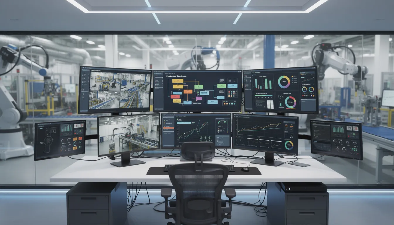
    • Supervisory systems such as SCADA, HMI, and historian servers that visualize, log, and coordinate process data and alarms.
    • Engineering and maintenance workstations used to configure control logic, update firmware, and manage system configuration.
    • Industrial networks and communication protocols that connect devices, controllers, and supervisory systems.
    • Supporting infrastructure including time synchronization, authentication services, and sometimes interfaces to IT systems.

    Use in manufacturing and regulated environments

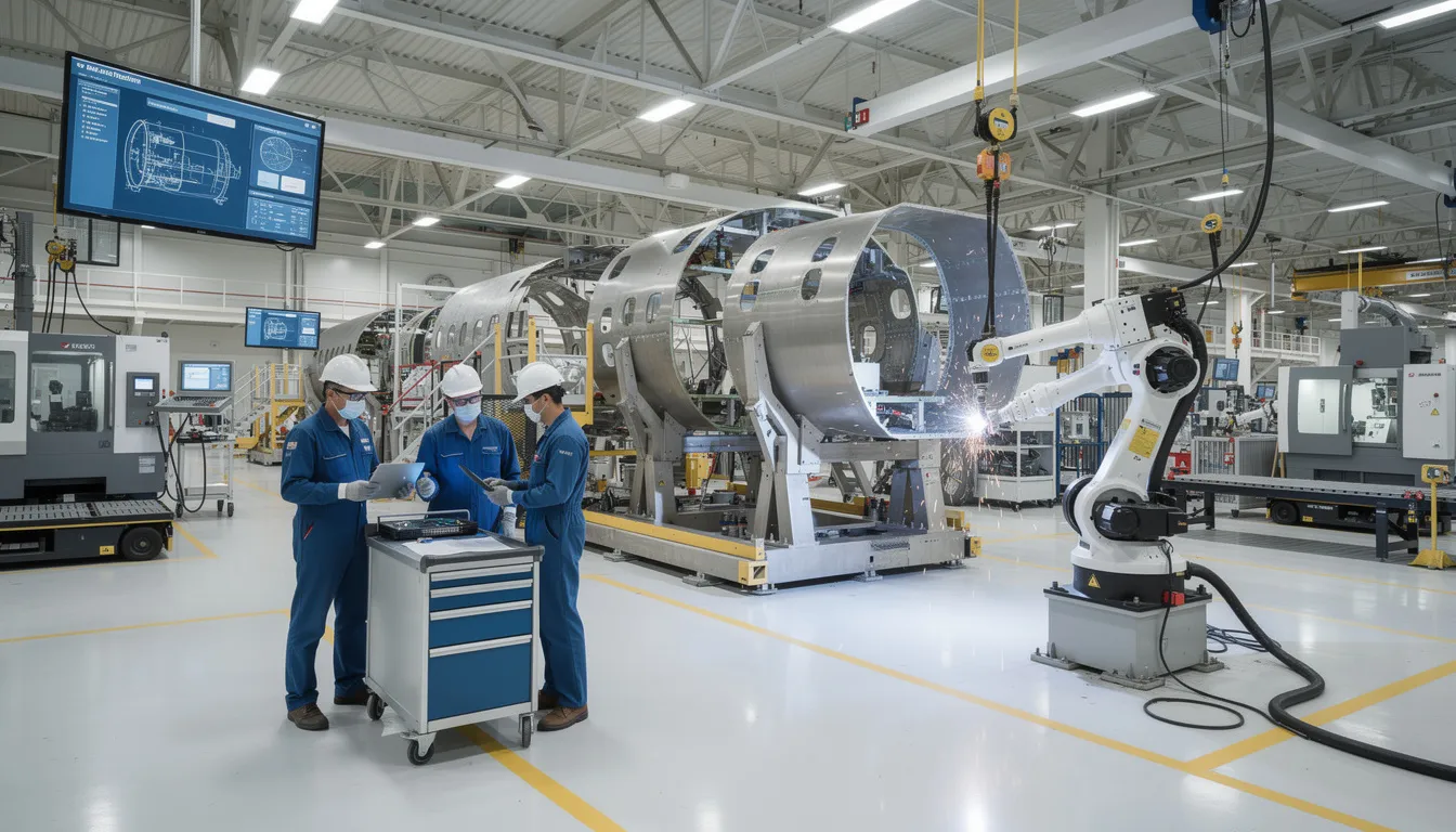
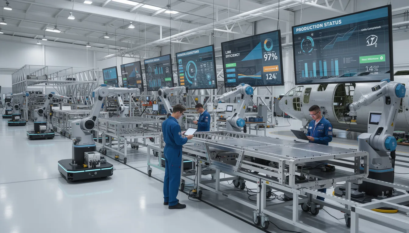
    In manufacturing plants and other regulated operations, IACS are used to control production lines, utilities, and supporting processes. They influence product quality, equipment performance, data integrity, and worker safety. Example uses include:

    • Automated control of mixing, filling, packaging, and assembly operations.
    • Monitoring of critical parameters such as temperature, pressure, and flow.
    • Interlocks, safety functions, and shutdown logic at the control level.
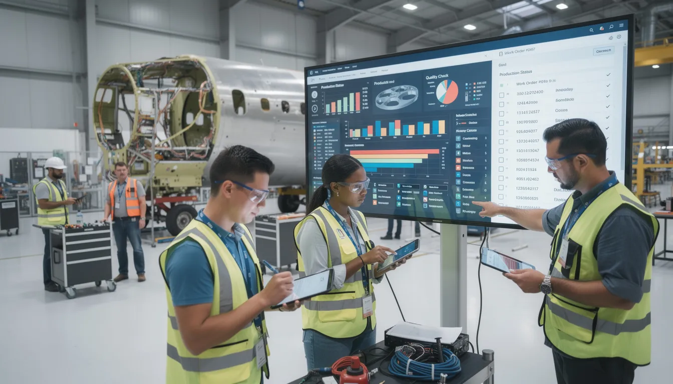
    • Data collection for batch records, traceability, and audit trails when integrated with MES or quality systems.

    Because IACS directly affect physical processes, changes to configuration, software, or topology are often subject to formal change control, validation, and documented testing, especially in regulated industries.

    Relationship to cybersecurity and IEC 62443

    Industrial automation and control systems are a primary focus of industrial cybersecurity standards such as IEC 62443. In that context, IACS are treated as cyber-physical systems that require:

    • Identification and segmentation of control system assets and zones.
    • Defined roles and responsibilities for asset owners, integrators, and product suppliers.
    • Controls for secure development, configuration, operation, and maintenance over the system lifecycle.

    Cybersecurity for IACS considers not only confidentiality and integrity of data, but also availability and correct, timely control of the physical process.

    Scope and boundaries

    The term industrial automation and control systems commonly includes:

    • Process control systems (PCS) and distributed control systems (DCS).
    • Programmable logic controllers (PLCs) and their associated networks.
    • Supervisory control and data acquisition (SCADA) systems.
    • Building automation or utility control systems when they are part of industrial operations.

    It typically excludes general office IT systems (email, office productivity tools), business-only applications (CRM, HR), and consumer automation devices, even when they share similar technologies.

    Common confusion

    • IACS vs IT systems: IACS are focused on controlling physical processes in real time; IT systems are focused on information processing, storage, and business workflows. In many plants, the two are interconnected but governed differently.
    • IACS vs SCADA/PLC: SCADA or PLCs are specific system types or components. IACS is a broader term that covers the full set of industrial control equipment, software, and networks.
    • IACS vs OT: OT (operational technology) is a broad category of technologies that monitor or control physical devices and processes. IACS are a major subset of OT, focused specifically on automation and control.
  • PLCs

    Core meaning

    PLCs (programmable logic controllers) are industrial digital computers designed for reliable control, sequencing, and monitoring of machinery and processes, typically in manufacturing and other industrial environments.

    They execute control logic in real time, reading inputs (for example sensors and switches) and driving outputs (for example valves, motors, relays) according to a user-defined program.

    Typical characteristics

    Common characteristics of PLCs in industrial operations include:

    – **Industrial hardening**: Designed to operate in harsh conditions (temperature, vibration, electrical noise) typical of shop floors.
    – **Deterministic control**: Run cyclic scan-based programs to provide predictable control behavior.
    – **Specialized I/O**: Support for discrete and analog inputs/outputs, and often motion, safety, or high-speed counters.
    – **Programming model**: Typically programmed using IEC 61131-3 languages such as ladder diagram (LD), function block diagram (FBD), structured text (ST), instruction list (IL), or sequential function chart (SFC).
    – **Real-time communication**: Connect to higher-level systems (SCADA, DCS, MES, historians) via industrial networks (for example EtherNet/IP, PROFINET, Modbus/TCP).

    Role in manufacturing systems

    In manufacturing and regulated environments, PLCs commonly:

    – Control production equipment such as filling lines, packaging machines, reactors, and conveyors.
    – Enforce basic **interlocks and safety-related logic** (often in conjunction with dedicated safety PLCs or relays).
    – Provide **process and event data** (states, counts, alarms, setpoints, process values) to OT and IT systems.
    – Support **recipe and parameter management** when integrated with MES or SCADA.
    – Participate in **batch and continuous control** under a supervisory system or as standalone controllers.

    PLCs typically operate at or near the ISA-95 level 1–2 layers (sensing, manipulation, and area control), feeding data to level 3 systems such as MES.

    Boundaries and exclusions

    In this site context, “PLCs” generally **includes**:

    – Classic rack-based controllers and compact/micro PLCs.
    – Safety-rated PLCs used for functional safety, when clearly identified as such.
    – PLC-like programmable automation controllers (PACs) when they are used for discrete and process control in similar ways.

    It generally **excludes**:

    – Simple, fixed-function logic modules or relay logic that cannot be user-programmed.
    – General-purpose industrial PCs that do not implement deterministic control logic in a PLC-like runtime.
    – High-level systems such as DCS or SCADA, which orchestrate or supervise PLCs rather than replace them.

    Common confusion and related terms

    – **PLCs vs. PACs**: Programmable automation controllers (PACs) are often more powerful, with richer data handling and networking. In many plants the term “PLC” is used informally to cover both.
    – **PLCs vs. DCS**: A DCS (distributed control system) is a higher-level, integrated control platform typically used in process industries. It may include PLCs or PLC-like controllers as field devices.
    – **PLCs vs. SCADA**: SCADA (supervisory control and data acquisition) provides visualization, alarming, and supervisory control. PLCs perform the low-level real-time control that SCADA supervises.
    – **PLCs vs. MES**: MES (manufacturing execution systems) manage production workflows, orders, and genealogy at the operations level. They consume and contextualize data coming from PLCs but do not replace them on the control layer.

    Use in predictive maintenance and analytics (site context)

    For predictive maintenance and related analytics:

    – PLCs are often the **primary source of time-series equipment data**, such as run/stop status, cycle counts, faults, and basic process values.
    – They may provide data to **historians**, **condition monitoring systems**, or **CMMS** via OPC servers or other protocols.
    – When integrated with an **MES**, PLC data can be linked to product, route, and operator information, allowing more contextualized analysis (for example, fault patterns per product or per line).

    In many architectures, predictive models do not run on the PLC itself but use data originating from PLCs, combined with MES or historian data, for analysis and anomaly detection.

  • indicator of compromise

    An indicator of compromise (IOC) is a technical artifact, pattern, or data point that suggests a system, device, or network may have been breached, misused, or otherwise affected by malicious activity. In industrial and regulated environments, IOCs are used by OT and IT security teams to detect, investigate, and respond to potential cyber incidents affecting production systems, corporate networks, and connected equipment.

    What an indicator of compromise includes

    IOCs commonly refer to observable items such as:

    • Network indicators, for example suspicious IP addresses, domains, URLs, or unusual traffic patterns involving control networks
    • Host-based indicators, such as unknown executables, malware file hashes, modified binaries, unusual services, or unexpected user accounts
    • Log or event patterns, such as repeated failed logins, abnormal protocol use on OT networks, or unexpected configuration changes
    • Email and identity indicators, such as known phishing sender addresses or abused user credentials
    • Industrial-specific signals, such as unauthorized firmware versions on PLCs, unexpected changes to recipes, or unauthorized remote access sessions to HMIs or engineering workstations

    In cyber threat intelligence, IOCs are typically considered a form of technical or tactical intelligence, because they can be directly consumed by tools such as firewalls, IDS/IPS, SIEMs, endpoint protection, and OT monitoring platforms.

    What an indicator of compromise does not include

    The term usually does not refer to:

    • Business-level impacts (for example production downtime metrics or financial loss)
    • High-level threat narratives or adversary motivations, which are more strategic intelligence
    • Vulnerabilities themselves (such as unpatched software) unless there is evidence they are being actively exploited

    Operational use in manufacturing and OT

    In industrial and regulated environments, IOCs are often:

    • Ingested into monitoring systems to alert on known bad IPs, domains, or file hashes relevant to OT and IT assets
    • Correlated with plant logs (for example historian, MES, or engineering station logs) to identify possible compromise of production equipment
    • Used during incident response to scope which lines, sites, or systems may be affected
    • Maintained in allow/deny or watch lists that are periodically reviewed and updated as threats change

    Common confusion

    Indicator of compromise vs. indicator of attack (IOA): An indicator of compromise usually reflects evidence that a compromise may have already occurred (for example a known malware hash found on a system). An indicator of attack focuses more on behaviors and sequences of actions that suggest an attack is in progress, even before a clear compromise artifact exists. Many operational security programs use both IOCs and IOAs together.

    Relation to cyber threat intelligence (CTI)

    Within cyber threat intelligence, IOCs are one of the main outputs of tactical and technical CTI. They translate higher-level knowledge about adversaries and campaigns into concrete, machine-readable items that OT and IT teams can deploy in sensors, gateways, and monitoring tools across industrial environments.

  • What is the best way to structure a DMZ between IT and OT networks?

    A DMZ between IT and OT is a security pattern, not a single blueprint. In regulated, long-lifecycle plants, the “best” structure is one that reduces risk while remaining operable, maintainable, and supportable across legacy systems, vendor constraints, and validation requirements.

    Core principles for an IT/OT DMZ

    Before deciding on specific topology, align on a few principles that are usually non-negotiable in regulated environments:

    • Segregation of duties and zones: IT, DMZ, and OT should be distinct security zones with explicit policies, not just VLANs on the same flat network.
    • Least privilege for connectivity: Only flows required for operations, monitoring, or compliance are allowed, and they are tightly scoped by source, destination, protocol, and port.
    • Minimize OT exposure: OT assets (PLCs, DCS, SCADA, historian, MES servers) should never be directly reachable from the corporate network or the internet.
    • Deterministic and auditable paths: Every route between IT and OT is known, documented, and controllable under change control.
    • Protocol and vendor reality: The design must accommodate OT protocols, vendor remote support requirements, and obsolete operating systems without pretending they are easily replaced.

    Common DMZ reference structure

    A common and generally defensible approach in manufacturing is a two-firewall DMZ with clearly separated functions:

    • Firewall 1 (IT edge to DMZ): Separates corporate/enterprise IT from the DMZ.
    • DMZ zone: Hosts systems that must communicate with both IT and OT but are not allowed to initiate direct sessions into OT uncontrolled.
    • Firewall 2 (DMZ to OT edge): Separates OT from the DMZ, typically with more restrictive rules and higher scrutiny.

    In many plants, the firewalls are from different vendors to reduce common-mode vulnerabilities, but this is not always achievable, especially where validation and support are constrained.

    What typically belongs in the DMZ

    Systems in the DMZ should be those that legitimately require bidirectional communication with both IT and OT but where compromise should not immediately compromise control systems. Typical examples include:

    • Replication and integration endpoints:
      • Historian replication servers (OT historian to enterprise historian)
      • MES/ERP integration brokers or application gateways
      • Middleware or message queues bridging plant data to enterprise analytics
    • Remote access termination:
      • Jump hosts / bastion servers used by vendors or engineering for remote access
      • VPN concentrators that terminate partner or vendor connections
    • Security and monitoring tooling:
      • Central log collectors or SIEM connectors that forward OT logs to enterprise SIEM
      • Passive OT network monitoring sensors that export data northbound
    • Patch and update staging (where feasible):
      • Antivirus/EDR update relays
      • Patch management staging servers used for OT (often with additional manual gating)

    By contrast, PLCs, RTUs, controllers, and core HMI/SCADA servers usually stay in the OT zone, not in the DMZ.

    Traffic patterns: one-way vs controlled bidirectional

    The most robust designs start from the premise that OT should not depend on inbound traffic from IT to keep producing. Under that assumption:

    • Prefer one-way or data-export patterns where possible:
      • OT historian sends data to DMZ historian or replication node.
      • DMZ node then forwards subsets to enterprise analytics or cloud endpoints.
      • For strict segregation, data diodes or unidirectional gateways can enforce one-way flows, though these introduce cost and operational complexity.
    • When bidirectional is required:
      • Restrict connections to specific application gateways or integration services in the DMZ.
      • Disallow direct desktop-to-PLC or corporate-laptop-to-HMI sessions.
      • Use jump hosts with multi-factor authentication and strong session recording where remote administration is needed.

    In practice, brownfield OT often requires some level of bidirectional communication for MES, recipe management, electronic batch records, and quality systems. The key is to concentrate and mediate this traffic via DMZ-resident services instead of exposing OT directly to IT.

    Segmentation within OT and the DMZ

    A DMZ is not a substitute for proper segmentation inside OT networks. In many plants, the more realistic goal is:

    • Tiered OT zones: Separate safety systems, critical control networks, and less critical monitoring networks, each with its own policies.
    • Cell or line-level segmentation: Use VLANs and firewalls or industrial security appliances to prevent lateral movement across manufacturing lines.
    • DMZ micro-segmentation: Group DMZ hosts by function (e.g., integration, remote access, monitoring), and limit east-west traffic so compromise of one host does not expose all others.

    These measures can usually be introduced incrementally, which is important when downtime for large redesigns is not practical.

    Identity, access control, and monitoring

    Structuring the DMZ is not only about topology. In regulated environments, the following controls are often as critical as the network design itself:

    • Centralized identity for DMZ and OT edge systems where feasible: For example, a dedicated OT Active Directory forest, selectively federated with IT, to keep blast radius smaller while enabling traceable user access.
    • Strong authentication for jump hosts and remote access: Multi-factor authentication, short-lived credentials, and role-based access help enforce least privilege.
    • Logging and monitoring: DMZ firewalls, jump hosts, and integration servers should feed logs to a SIEM, with clear ownership for triage and response.
    • Configuration management and baselines: Golden images, hardened builds, and documented baselines are important for demonstrating due diligence and supporting incident investigation.

    Change control, validation, and lifecycle realities

    In regulated, long-lifecycle manufacturing, DMZ architectures must respect:

    • Change control and validation: Any changes to firewall rules, DMZ-hosted integration components, or remote access patterns typically fall under formal change management. For GxP or aerospace, they may require validation or re-qualification of connected systems.
    • Downtime constraints: Large-scale network re-segmentation or firewall replacement may not be practical if they require prolonged outages across multiple lines or test cells.
    • Vendor and protocol lock-in: Many OT assets run obsolete operating systems or proprietary protocols that limit hardening options and force compromises in DMZ design.
    • Long asset lifetimes: Controllers and OT servers may be in place for 10–20 years. The DMZ needs to be designed with an expectation of coexisting with multiple generations of equipment and systems.

    Because of these constraints, full rip-and-replace network architectures are rarely viable. Most plants incrementally move toward a stronger DMZ posture by:

    • Standing up the DMZ and firewalls first with minimal, well-controlled traffic.
    • Gradually migrating integrations and remote access paths into the DMZ.
    • Tightening rules and decommissioning legacy direct connections as each dependency is addressed and, where needed, revalidated.

    Interactions with existing MES, ERP, and cloud integrations

    Any DMZ design must co-exist with existing systems:

    • MES and batch systems: Often require deterministic, low-latency communication with controllers. Placing core MES servers inside OT and using DMZ-based integration nodes for ERP/cloud is a common compromise.
    • ERP and PLM: Typically stay on IT. Data exchange via message brokers, web APIs, or file drops should pass through the DMZ, not direct OT-to-ERP links.
    • Cloud-based analytics or historian services: DMZ-based gateways or collectors are typically used to manage outbound-only connections and to buffer data if connectivity is disrupted.

    Every such integration should have clearly documented data flows, ownership, and failure modes, especially where production release decisions or quality records depend on those data.

    Key tradeoffs and design decisions

    When determining the “best” DMZ structure for your environment, expect to explicitly weigh:

    • Security vs. operational flexibility: Stronger isolation (e.g., one-way gateways) improves security but can limit remote troubleshooting and increase MTTR without parallel processes.
    • Complexity vs. supportability: Multiple firewalls, micro-segmentation, and diverse vendors improve defense-in-depth but can strain local support teams if documentation and training lag.
    • Standardization vs. plant-specific realities: Corporate-standard architectures are desirable, but plants with older or more sensitive assets may need exceptions and phased adoption.
    • Upfront redesign vs. incremental hardening: Big-bang re-architecture can be efficient in theory but is usually hard to validate and schedule. Incremental improvements are more survivable, though they can leave temporary gaps.

    How to move toward a robust IT/OT DMZ

    In practice, most organizations advance through stages rather than achieving an ideal design immediately:

    1. Document current flows: Identify all existing IT/OT connections, including “temporary” ones that became permanent.
    2. Define target zones and basic DMZ: Agree on what belongs in IT, DMZ, and OT, and implement core firewalls.
    3. Migrate high-risk traffic first: Remote access and direct OT exposure to IT or internet should be routed through DMZ-based jump hosts or gateways.
    4. Introduce logging and monitoring: Ensure that DMZ and firewall activities are observable and that responsibility for review is assigned.
    5. Refine and validate: Iterate on rules and zoning as you learn, incorporating formal change control and, where applicable, validation testing.

    Because every plant’s legacy stack, regulatory context, and vendor ecosystem is different, the best DMZ structure is the one that achieves a defensible balance of isolation, operability, traceability, and long-term maintainability for your environment.

  • What is the scope in ISO 27001?

    In ISO 27001, the scope is the formal, written definition of what parts of your organization the Information Security Management System (ISMS) applies to. It sets the physical, organizational, and technical boundaries within which you manage information security risks according to the standard.

    What the ISO 27001 scope must cover

    The scope statement should clearly identify:

    • Organizational boundaries: Business units, legal entities, and functions covered (for example: corporate IT only, or corporate IT plus selected plants).
    • Physical locations: Sites, offices, data centers, and plants that are in scope, including remote or hosted environments.
    • Information and processes: Types of information and the processes that create, process, store, or transmit it (for example: production planning, quality records, engineering data, supplier data).
    • Systems and technologies: Applications, infrastructure, OT/ICS, and cloud services governed by the ISMS.
    • Interfaces and dependencies: How in-scope systems interact with out-of-scope systems, partners, and suppliers.

    The scope must be consistent with your context, risk assessment, and interested parties. ISO 27001 does not dictate a single “correct” scope, but the scope cannot be defined in a way that hides or ignores significant information security risks.

    How scope works in complex manufacturing environments

    In regulated, brownfield operations, the scope decision has practical constraints:

    • Legacy and OT systems: Many plants have SCADA, PLCs, and legacy MES that are difficult to patch or monitor. You must explicitly decide whether these are in or out of scope, and document the rationale and compensating controls if excluded.
    • Mixed vendor stacks: ERP, MES, PLM, QMS, and data historians from multiple vendors typically span IT and OT. If you include one layer in scope (for example, MES), interfaces to out-of-scope layers must still be risk-assessed and controlled.
    • Downtime and change windows: A wider scope can increase the operational impact of required controls (for example, change control for firewall rules on production cells), so scope must be realistic about what can be governed without jeopardizing uptime.
    • Long lifecycle equipment: Some assets will not support modern controls. The scope statement should acknowledge these limitations and point to risk acceptance, isolation, or layered controls instead of implying full technical conformity.

    Typical scope patterns

    In practice, organizations in industrial and regulated environments often choose one of these patterns:

    • Corporate IT only: The ISMS covers corporate networks, business applications, and central services. OT and shop-floor systems are explicitly out of scope, but are recognized as interfaces or dependencies.
    • Selected plants or value streams: The ISMS covers specific sites, lines, or programs, usually where regulatory or customer pressure is highest, with a plan to expand over time.
    • Integrated IT/OT scope: The ISMS covers both corporate IT and defined OT environments (for example, all lines producing a certain regulated product), with explicit recognition of legacy constraints and tailored controls.

    A full “everything, everywhere” scope can be attractive on paper but frequently fails in long-lifecycle environments because it becomes too costly to implement, validate, and maintain controls across all assets and sites, especially where downtime and change control are heavily constrained.

    Key tradeoffs when defining ISO 27001 scope

    • Coverage vs. implementability: A broad scope provides better risk coverage but is harder to operationalize and maintain, especially across multiple plants and vendors.
    • IT vs. OT inclusion: Including OT increases relevance to real production risk, but also increases complexity, integration challenges, and the need for OT-specific controls and competencies.
    • Regulatory & customer expectations: A narrow scope may meet the letter of ISO 27001 but may not satisfy aerospace, defense, or pharma customers if critical production or technical data environments are excluded without a clear rationale.
    • Evidence and traceability burden: A wider scope multiplies the volume of assets, changes, and records you must control and evidence. In environments with strict validation and change control, this can be a major operational load.

    Practical considerations for defining scope

    When you draft your ISO 27001 scope in an industrial context:

    • Base it on a documented understanding of your business processes and information flows, not just org charts.
    • Describe boundaries in terms of processes, sites, and systems so it is clear what is included and excluded.
    • Identify critical interfaces to other systems and partners, and show how those risks are addressed even if the external systems are out of scope.
    • Ensure the scope is stable enough to be maintained over the life of your assets, but flexible enough to extend as you modernize.
    • Keep the scope statement aligned with your risk assessment and Statement of Applicability so auditors and customers can trace your logic.

    The result should be a scope that is realistic for your brownfield environment, transparent about constraints, and supportable over time without implying guarantees you cannot operationally sustain.

  • Industrial control system (ICS)

    An industrial control system (ICS) is the collection of hardware, software, and communication networks used to monitor, control, and automate industrial processes. ICS environments are common in manufacturing plants, utilities, and other industrial operations where physical equipment such as valves, motors, conveyors, reactors, or packaging lines must be controlled in real time.

    What an ICS includes

    An ICS typically combines several types of components into a single operational environment, for example:

    • Field devices that interact directly with the process, such as sensors, actuators, and variable frequency drives
    • Controllers such as programmable logic controllers (PLCs), remote terminal units (RTUs), or distributed control system (DCS) controllers
    • Human-machine interfaces (HMIs) and operator stations used to monitor status, acknowledge alarms, and issue commands
    • Supervisory systems such as SCADA servers or DCS workstations that coordinate plant-wide control and data collection
    • Control and operations networks that connect controllers, HMIs, historians, and plant servers
    • Supporting infrastructure such as engineering workstations, historians, and sometimes interface gateways to MES, ERP, or quality systems

    In regulated manufacturing environments, the ICS often operates alongside or under higher-level systems such as MES and quality management systems, but it remains responsible for the direct and time-critical control of equipment and processes.

    Where ICS is used

    Industrial control systems are used across many sectors, including:

    • Discrete manufacturing (assembly lines, packaging, machining cells, test stands)
    • Batch and continuous process industries (pharmaceutical, chemical, food and beverage)
    • Utilities and infrastructure (water treatment, power generation, pipelines)

    In each case, the ICS focuses on safe, reliable operation of physical processes, often with strict uptime, quality, and safety requirements.

    ICS and cybersecurity

    Because ICS environments depend on interconnected devices and networks, they are a focus area for operational technology (OT) cybersecurity. ICS security commonly refers to the technical, procedural, and physical controls used to protect control equipment, control networks, and related systems. In manufacturing, security measures must account for legacy equipment, change control, and validation requirements, while maintaining process safety and availability.

    Common confusion

    • ICS vs. SCADA: SCADA (supervisory control and data acquisition) is a type of system used for high-level monitoring and control, often over geographically distributed assets. An ICS is broader and may include SCADA, DCS, PLCs, and other components.
    • ICS vs. OT: Operational technology (OT) is a broad category that includes ICS but can also include other embedded and facility systems. ICS specifically refers to the control environment for industrial processes.
    • ICS vs. MES: A manufacturing execution system (MES) manages production workflows, scheduling, and traceability at the operations level. The ICS directly controls equipment and real-time process variables, and often exchanges data with MES but serves a different function.

    Operational perspective

    From an operational standpoint, an ICS is where automation logic runs and where plant operators interact with the process. Typical activities include:

    • Configuring and maintaining control logic in PLCs or DCS controllers
    • Monitoring trends, alarms, and equipment status through HMIs
    • Coordinating data exchange with historians, MES, and quality systems
    • Managing changes under formal change control in regulated environments

    In regulated or validated manufacturing, documentation and evidence related to ICS configuration, changes, and operation are often required for quality and compliance purposes.

  • industrial control system

    An industrial control system (ICS) is a broad term for the hardware, software, communication networks, and related procedures used to monitor, control, and automate industrial processes. ICS are typically deployed in manufacturing plants, utilities, and other operational technology (OT) environments to interact directly with machinery, sensors, actuators, and process equipment.

    Core characteristics

    Industrial control systems commonly include:

    • Field devices such as sensors, transmitters, drives, and actuators that measure and manipulate physical processes.
    • Control devices such as programmable logic controllers (PLCs), remote terminal units (RTUs), and distributed control system (DCS) controllers that execute control logic.
    • Human-machine interfaces (HMIs) and engineering workstations used by operators and engineers to monitor status, adjust setpoints, and modify control logic.
    • Communication networks using industrial protocols (for example, Modbus, PROFINET, EtherNet/IP) to connect controllers, field devices, and supervisory systems.
    • Supervisory and historian systems such as SCADA servers, data historians, and alarm systems that aggregate, visualize, and record process data.

    ICS operate close to the physical process and are designed with real-time or near real-time constraints. They often prioritize availability and predictable behavior, and may have long life cycles compared with enterprise IT systems.

    Scope and boundaries

    In industrial and regulated manufacturing environments, the term ICS typically includes:

    • Automation and control infrastructure at the plant or site level.
    • Process control and safety-related control (such as emergency shutdown systems), where applicable.
    • Connections from plant-floor control networks to higher-level systems (for example, MES or historians), when these connections are part of the control architecture.

    It usually does not include purely business IT systems such as ERP, office productivity tools, or standalone quality management software unless they are directly embedded into or tightly coupled with the control environment.

    Operational context

    In day-to-day operations, industrial control systems:

    • Monitor process variables (such as temperature, pressure, flow, and position).
    • Execute control algorithms (such as PID control, sequencing, and interlocks).
    • Generate alarms and events for operators and maintenance teams.
    • Interface with manufacturing execution systems (MES) and other OT/IT systems to exchange production orders, quality data, and status information.

    In regulated industries, ICS configuration, change control, and data handling are often subject to documented procedures and verification, especially when they affect product quality, safety, or compliance-related records.

    ICS and security standards

    Industrial control systems are a primary focus of OT cybersecurity standards such as the IEC 62443 series, which commonly address the security of control and automation systems across their life cycle. These standards distinguish ICS security requirements from those of enterprise IT security frameworks, such as ISO/IEC 27001, which focus on information security management for broader organizational assets.

    Common confusion

    • ICS vs. SCADA: SCADA (Supervisory Control and Data Acquisition) systems are a subset of ICS focused on high-level monitoring and supervisory control, often across geographically distributed assets. ICS is the broader term that can include SCADA, DCS, and PLC-based control architectures.
    • ICS vs. OT: OT (operational technology) refers to all hardware and software that detects or causes changes in the physical world. ICS is a major category within OT, but OT can also include building management, access control, and other non-process systems.
    • ICS vs. IT: IT systems manage data processing and business applications, while ICS directly control physical processes. In modern plants, ICS and IT are often interconnected, which drives the need for clear network segmentation, governance, and coordinated security controls.

    Derived-from context: 62443 vs. 27001

    Where IEC 62443 is mentioned alongside ISO/IEC 27001, industrial control systems refer to the automation and control environment that IEC 62443 targets, including controllers, HMIs, networks, and supporting systems in the plant. ISO/IEC 27001 typically applies to the organization’s information security management system, and the ICS environment is integrated through governance, risk management, and technical controls that align both perspectives.

  • NIST SP 800-82

    NIST SP 800-82 is a special publication from the U.S. National Institute of Standards and Technology (NIST) that provides guidance on the security of Industrial Control Systems (ICS). It focuses on how to protect operational technology (OT) environments such as manufacturing control systems, distributed control systems (DCS), and supervisory control and data acquisition (SCADA) systems.

    The document describes typical ICS architectures, identifies common vulnerabilities and threat scenarios, and outlines recommended practices for securing control systems throughout their lifecycle. It covers topics such as network segmentation, access control, monitoring, incident response, and system hardening for environments that manage physical processes.

    Use in industrial and regulated environments

    In manufacturing and other regulated industries, NIST SP 800-82 is commonly used as a reference for:

    • Designing and reviewing OT network architectures for production lines, utilities, and facility systems
    • Aligning security controls for PLCs, HMIs, historians, MES interfaces, and gateways connecting OT and IT networks
    • Supporting risk assessments and cybersecurity programs for plants, laboratories, and other process facilities
    • Coordinating with IT security frameworks, such as controls cataloged in NIST SP 800-53, for environments that combine ICS, MES, and ERP systems

    The guidance is descriptive and advisory. It does not by itself establish legal compliance or guarantee audit outcomes. Organizations typically adapt its recommendations to their specific processes, equipment, and regulatory obligations.

    What NIST SP 800-82 includes and excludes

    NIST SP 800-82 primarily includes:

    • Security considerations for ICS components such as controllers, sensors, actuators, engineering workstations, and control networks
    • Recommended security controls and practices tailored for safety- and reliability-critical OT environments
    • Guidance on integrating ICS into broader enterprise security programs

    It does not:

    • Serve as a detailed equipment manual or vendor-specific configuration guide
    • Provide certification or formal compliance status for an organization or system
    • Replace sector-specific regulations or standards that may impose additional requirements

    Common confusion

    NIST SP 800-82 is sometimes confused with:

    • NIST SP 800-53, which provides a broad catalog of security and privacy controls for federal information systems and organizations. SP 800-82 focuses specifically on ICS and OT environments and may reference or adapt controls from SP 800-53.
    • Sector-specific standards for industrial cybersecurity, such as ISA/IEC 62443. NIST SP 800-82 is a NIST guidance document and is not the same as these standards, although it addresses many of the same technical and operational security topics.

    Relationship to security controls

    NIST SP 800-82 commonly refers to security controls and practices that can be selected and tailored for ICS and OT. Organizations often use it together with generic control catalogs, such as those in NIST SP 800-53, to decide which technical, administrative, and physical safeguards to apply in their industrial environments.

  • Distributed Control System

    A Distributed Control System (DCS) is an industrial automation architecture in which process measurement, control, and supervisory functions are performed by multiple networked controllers distributed across a plant or facility. It is commonly used in continuous or batch process industries such as chemicals, oil and gas, power generation, and pharmaceuticals.

    In a DCS, field devices (such as sensors and actuators) connect to input/output (I/O) modules that are associated with controllers. These controllers execute control strategies, such as PID loops, logic sequences, and interlocks, according to configuration data stored in the system. The controllers communicate over an industrial network with operator stations and engineering workstations.

    Typical components of a DCS include:

    • Field instruments and actuators
    • Remote or local I/O modules
    • Process controllers
    • Operator consoles and human–machine interfaces (HMIs)
    • Engineering and configuration stations
    • History, alarm, and event servers
    • Industrial communication networks

    Operationally, a DCS provides centralized monitoring and supervisory capabilities while distributing real-time control execution close to the process. It is often referenced in standards and models such as ISA‑95, where it typically falls within the control and operations levels of an industrial automation hierarchy.

  • Programmable Logic Controller (PLC)

    A programmable logic controller (PLC) is an industrial-grade digital control device used to automate machinery and processes, typically at the equipment or line level. PLCs monitor inputs from sensors and operator interfaces, execute control logic in real time, and drive outputs such as motors, valves, actuators, and alarms.

    Core characteristics

    PLCs commonly:

    • Provide deterministic, real-time control of machines and process equipment
    • Use rugged hardware designed for harsh industrial environments
    • Run user-defined programs, often written in ladder logic, function block, or structured text
    • Interface with field devices through digital and analog I/O modules
    • Communicate over industrial networks (for example, Ethernet/IP, PROFINET, Modbus) with HMIs, SCADA, MES, and other systems

    Role in manufacturing systems

    In typical manufacturing architectures, PLCs sit close to the physical process. They:

    • Execute interlocks, sequences, and safety-related control at the machine or cell level
    • Collect real-time status such as sensor states, counts, speeds, and basic quality conditions
    • Expose tags or data points that higher-level systems (SCADA, MES, historians) can read or write
    • Support recipe parameters or setpoints provided by supervisory systems but do not manage full production orders

    PLCs are often integrated with manufacturing execution systems (MES), which use PLC data for tracking production, enforcing workflows, and maintaining traceability. The PLC focuses on equipment control, while MES and other IT/OT systems handle orchestration, materials, records, and compliance-related evidence.

    What a PLC is not

    • It is not a MES or ERP. It does not manage orders, full electronic batch records, or enterprise planning.
    • It is not a general-purpose computer. PLCs are optimized for deterministic control, not for broad computing tasks.
    • It is not, by itself, a full safety system. Safety PLCs and dedicated safety circuits are used in combination with standards-based designs.

    Common confusion

    • PLC vs SCADA/HMI: The PLC performs the control logic. SCADA and HMI systems provide visualization, operator interaction, and supervisory control, often by connecting to multiple PLCs.
    • PLC vs DCS: A distributed control system (DCS) is typically used for large, process-oriented plants with integrated control and supervision. PLCs are often used for discrete manufacturing or modular equipment, though there is overlap.
    • PLC vs industrial PC (IPC): An IPC is a computer platform. A PLC is a control device with a real-time runtime and industrial I/O tightly integrated.

    Connection to MES and regulated environments

    In regulated and high-compliance manufacturing, PLCs provide time-stamped equipment data, basic alarms, and recipe execution at the machine level. MES or related systems use this data to support electronic records, deviations, traceability, and audit trails. A PLC alone typically does not provide the structured documentation, approvals, or lifecycle controls associated with compliance and quality systems.