RSC Content Type: Data Sheet / Proof Asset

KPI definitions, ROI math, or measurable outcome artifact.

  • CAPA in Aerospace: When to Start, What to Prove, and How to Close

    CAPA in Aerospace: When to Start, What to Prove, and How to Close

    CAPA aerospace workflows are often discussed only after something has already gone wrong: a recurring nonconformance, an audit finding, a supplier escape, or a field event that raises airworthiness concern. The issue is rarely the form itself. The issue is whether the organization knows when CAPA begins, what evidence belongs in the file, and what proves the fix actually worked.

    In aerospace manufacturing and MRO, CAPA is not a paperwork exercise. It is a controlled process for turning quality data into permanent solutions. Done well, it connects NCRs, MRB decisions, inspections, supplier records, customer feedback, and field events into one practical process for risk reduction and continuous improvement.
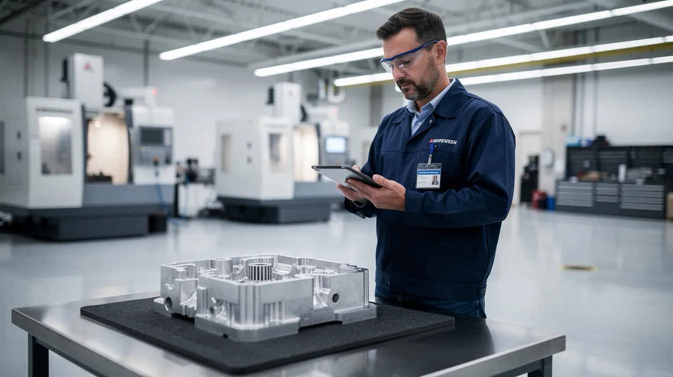
    An aerospace inspector is examining a machined component on a clean production floor while using a tablet, highlighting the importance of quality management systems and the effective CAPA (Corrective and Preventive Actions) process in ensuring regulatory compliance and continuous improvement in aerospace manufacturing.

    What is CAPA in Aerospace Manufacturing and MRO?

    CAPA stands for Corrective and Preventive Action. In practice, it means corrective and preventive actions taken through a formal, evidence based workflow. Corrective actions address known quality problems and prevent recurrence. Preventive actions address related risks before they become quality defects, escapes, or safety events.

    CAPA is familiar in medical devices, medical device manufacturing, and the way medical device companies manage quality system obligations under federal regulations. Medical device manufacturers often face strong regulatory scrutiny around CAPA documentation, root cause determination, and effectiveness checks. Aerospace has a different operating environment, but the expectation is similar: a capa process must be traceable, risk based, and supported by evidence.

    In aerospace production and MRO, CAPA sits inside the quality management system. It connects nonconformance reports, MRB decisions, internal audits, supplier issues, customer escapes, service difficulty signals, and field events into a closed loop. It is not just a qms capa record. It is the mechanism for proving that the production process, maintenance process, or supplier process has been brought back under control.

    AS9100D Clause 10.2 expects organizations to react to nonconformities, determine root cause, consider whether similar nonconformities exist, implement corrective actions, and evaluate effectiveness. FAA and EASA regulatory requirements, NADCAP special process expectations, and customer quality clauses all point toward the same operating truth: an effective capa system must produce records that show what happened, why it happened, what changed, and whether the change worked. Guidance on AS9100D nonconformity and corrective action requirements is summarized by AS9100 Store.

    Connect981 provides the digital backbone for this work across factories, suppliers, and MRO facilities. Instead of tracking a capa plan through spreadsheets, email threads, local folders, and disconnected quality systems, teams can link defects, inspection evidence, owners, action plans, change control, and closure evidence in one shared workflow.

    When Should a CAPA Be Opened in Aerospace Operations?

    A CAPA should be opened when the evidence points beyond a single defect and toward systemic issues, repeat risk, regulatory impact, or significant safety and airworthiness concern. CAPA does not begin automatically every time an NCR is written. A one off nonconformance can often be handled through NCR, MRB disposition, containment, and correction.

    The decision changes when the same type of problem repeats, when a single event has high consequence, or when an audit finding shows a weakness in the quality management process. In those cases, a corrective action plan is needed because the organization must understand root cause and change the system, not just fix the affected part.

    Under using CAPA hides systemic risk. Overusing CAPA creates noise, delays, and long backlogs that prevent the team from focusing on high risk issues. The best capa procedures use risk based prioritization. They define when the CAPA threshold has been met, who approves the decision, what evidence is needed, and how capa outcomes will be measured.

    Connect981 supports this decision by reading across NCRs, defects, rework, supplier records, audit findings, and process data. The platform can surface capa trends and AI assisted root cause signals so quality leaders can see whether an issue is isolated or part of a wider pattern.

    Trigger Logic: Clear Criteria for Opening a CAPA

    Aerospace organizations should document CAPA trigger logic in their procedures and configure it into the capa system. The decision should not depend on who happens to be reviewing the issue that day. It should be consistent, auditable, and aligned with regulatory expectations.

    Common CAPA triggers include:

    • Repeated nonconformances on the same part family, feature, process, work center, tool, or supplier within a defined period. A practical threshold is three similar NCRs within 90 days, although each organization should set criteria based on its own processes and risk profile.
    • A serious quality escape affecting delivered aircraft, flight hardware, maintenance release, or customer safety. Structural fastener torque issues discovered after delivery should trigger CAPA immediately.
    • Internal audits, AS9100 audits, NADCAP audits, FAA or EASA findings, or customer audits that identify systemic weakness or repeated minor findings in the same area.
    • A high Risk Priority Number from FMEA, a severe risk assessment outcome, or risk analysis showing that even a single occurrence could affect airworthiness, compliance, or mission reliability.
    • Supplier quality problems involving safety critical parts, long lead components, counterfeit risk, traceability gaps, or repeated documentation failures.
    • Customer feedback showing recurring escapes, late corrective measures, or dissatisfaction tied to the same process weakness.
    • Negative trend data in scrap, rework, inspection failures, test failures, MRO turnaround delays, or supplier controls.

    A CAPA trigger does not mean the answer is already known. It means the organization has enough evidence to justify a thorough investigation. In Connect981, these criteria can be built into configurable workflows so recurring defects, supplier performance drops, or high risk issues are flagged before they become audit findings or customer escapes.

    Examples: When Immediate Correction Is Enough vs. When CAPA Is Required

    A single routing sheet error may not justify CAPA. If one work order has an incorrect router code, the affected record can be corrected, the lot can be reviewed, and the operator or planner can be briefed. If there is no trend, no safety impact, and no evidence of a broken planning process, an NCR and correction may be enough.

    A recurring torque verification gap is different. If three work orders for the same part family show missing torque verification on critical structural fasteners, the issue has moved beyond correction. The capa investigation should review work instructions, tooling, inspection points, training, human factors, and whether the router allows the operation to be skipped.

    Supplier labeling follows the same logic. One mislabeled shipment of non flight hardware may be handled through MRB, receiving inspection, and supplier notification. Multiple mislabels from the same supplier over two months point to supplier process weakness. That requires CAPA, supplier corrective actions, and likely a preventive action plan covering similar part families or packaging flows.

    A field event can trigger CAPA without waiting for recurrence. If an aircraft or engine assembly shows a structural issue after delivery, the organization should open CAPA based on risk, not count. Connect981 helps by showing recurrence across shops, suppliers, programs, and MRO stations, giving quality teams the evidence to justify escalation.

    How CAPA Differs from NCR, MRB, and Immediate Containment

    CAPA is often confused with NCR, MRB, and containment because all four may appear in the same quality event. They are connected, but they do different work.

    • Nonconformance Report, or NCR: The NCR is the initial record of a defect or deviation on a part, assembly, process, document, or maintenance task. It often applies to a single work order, batch, serial number, or inspection record.
    • Material Review Board, or MRB: MRB is the engineering and quality decision process for dispositioning nonconforming product. Typical dispositions include use as is, repair, rework, scrap, or return to supplier. MRB decides the fate of product. It does not, by itself, solve the process failure.
    • Immediate containment or correction: Containment protects the customer, the aircraft, and production flow while the facts are being established. Examples include quarantine, stop use, stop shipment, added inspection, temporary rework, and suspect lot review.
    • CAPA: CAPA sits above NCR and MRB. It is triggered when data from those processes show deeper process failure, repeat risk, regulatory compliance exposure, or safety concern.

    The distinction matters. Containment may stop the bleeding, but it does not prove the root cause has been removed. MRB may release or scrap hardware, but it does not verify effectiveness of a process change. CAPA is the closed loop record that shows root cause, corrective or preventive actions, implementation evidence, and capa effectiveness.

    Connect981 links NCRs, MRB decisions, containment tasks, and CAPA records so teams can see the full chain from first defect through confirmed root cause and long term fix. The result is better traceability and fewer gaps during regulatory inspections.

    Practical Process Flow: From Deviation to CAPA

    A practical process keeps the handoffs clear:

    • Defect or deviation is logged as an NCR with part number, serial number, operation, work order, inspector, and evidence.
    • MRB reviews the affected product and determines disposition, such as rework, repair, scrap, use as is, or return to supplier.
    • Immediate containment protects the customer and production flow. Suspect inventory may be quarantined, shipments paused, or inspection expanded.
    • Quality performs trend review and risk assessment using NCR history, process data, audit findings, supplier records, and customer feedback.
    • CAPA is opened if trigger criteria are met. The capa owner is assigned, scope is defined, and the capa form becomes the umbrella record.
    • The investigation aggregates NCRs, MRB records, inspection results, supplier inputs, engineering analysis, and production evidence.
    • Corrective actions and preventive measures are implemented, verified, monitored, and reviewed for closure.

    In Connect981, this flow is modeled as linked digital workflows. Teams avoid duplicate data entry, evidence remains connected to the original event, and the audit trail is built as the work happens.
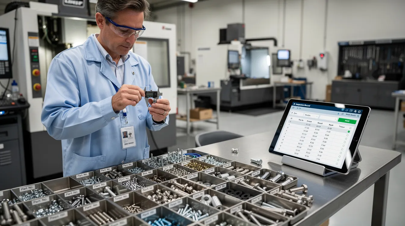
    A quality engineer is inspecting aerospace fasteners at a workstation, while digital records are displayed on a tablet, highlighting the importance of a quality management system in ensuring regulatory compliance and effective corrective actions. The scene emphasizes the role of continuous improvement and thorough investigation in the aerospace industry.

    The CAPA Investigation: Root Cause, Evidence, and Action Planning

    A real capa investigation starts with a clear problem statement. The statement should describe what failed, where it failed, when it was found, how many units were affected, which requirements were missed, and why the issue matters. Vague language creates weak investigations. A well documented CAPA file begins with operational facts.

    The investigation then defines scope. That includes affected parts, programs, suppliers, work centers, shifts, tools, routers, inspection points, MRO tasks, and potentially delivered product. The team should also evaluate whether similar nonconformities exist elsewhere. AS9100D expects this broader check, not only a review of the visible defect.

    Aerospace CAPA cannot stop at “operator error.” Human factors matter, but they must be examined in context. The team should review instruction clarity, training records, tooling condition, calibration, access to current revisions, environmental conditions, supervision, inspection plans, supplier controls, and change control history. EASA Part 145 environments also expect root cause and contributing factor analysis for findings, as summarized in industry guidance on aviation maintenance root cause analysis.

    Each CAPA should document the problem statement, scope, data sources, root cause analysis, corrective actions, preventive actions, and effectiveness verification plan. Connect981 keeps photos, NCRs, SPC charts, supplier emails, FAI reports, calibration logs, and revised work instructions linked to the CAPA record for fast retrieval during audits.

    Root Cause Analysis in Aerospace CAPA

    Root cause analysis is a disciplined method for separating symptoms from causes. It should be practical, not theatrical. The goal is root cause determination that can be tested against evidence and translated into corrective measures.

    Useful methods include:

    • 5 Whys for straightforward process breakdowns, such as a skipped verification step.
    • Fishbone or Ishikawa analysis for issues with multiple contributing factors, such as plating defects involving chemistry, tooling, handling, and inspection.
    • fault tree analysis for safety critical failures where event logic and failure paths must be understood.
    • FMEA review when the failure mode was known but risk management controls did not prevent occurrence or detection failure.
    • Process mapping when handoffs between planning, stores, inspection, MRO, or supplier teams are unclear.

    CAPA should involve cross functional teams when the issue crosses boundaries. A cross functional team may include quality, manufacturing engineering, design engineering, production, MRO leads, supply chain, supplier quality, and program management. In high consequence cases, organizations should involve cross functional teams early so the investigation does not optimize one department while missing the system failure.

    Connect981 can support RCA by surfacing similar events, defect history, supplier patterns, and prior capa actions. AI assisted root cause suggestions can point teams toward likely contributing factors, but the decision remains with engineering and quality. The confirmed root cause must be supported by evidence.

    Evidence Requirements: What Belongs in CAPA Documentation

    Good capa documentation tells a coherent story. An auditor, customer representative, or new quality manager should be able to understand what happened, why it happened, what changed, and how the organization verified the result.

    Typical evidence includes:

    • NCR history and defect records.
    • Scrap, rework, and repair trends before and after the event.
    • Inspection results, SPC charts, capability studies, and test data.
    • Photos, microscopy, measurement reports, or lab results showing the defect.
    • Calibration records, tool maintenance logs, and gage records.
    • Training records, qualification sign offs, and skill matrix updates.
    • Revised digital work instructions, routers, inspection plans, and control plans.
    • Change control approvals, ECOs, drawing updates, software revisions, or CNC program validation.
    • First Article Inspection records when the process or configuration changed.
    • Supplier corrective action reports, supplier audits, and receiving inspection evidence.
    • Risk assessment, risk analysis, and FMEA updates.
    • CAPA review notes, approvals, and management review inputs when appropriate.

    Each root cause should have supporting evidence. Each corrective action and preventive action capa item should also have proof that it was implemented. If the fix was an updated torque specification, the CAPA file should link to the approved specification, revised router, updated work instruction, and evidence that the station is using the current revision.

    Connect981 acts as a single evidence repository across ERP, MES, PLM, QMS, and supplier data. This matters because CAPA evidence often lives in fragments. One piece is in email, another in a file share, another in a supplier portal, and another on the shopfloor. Fragmented evidence creates audit risk even when the team did the right work.
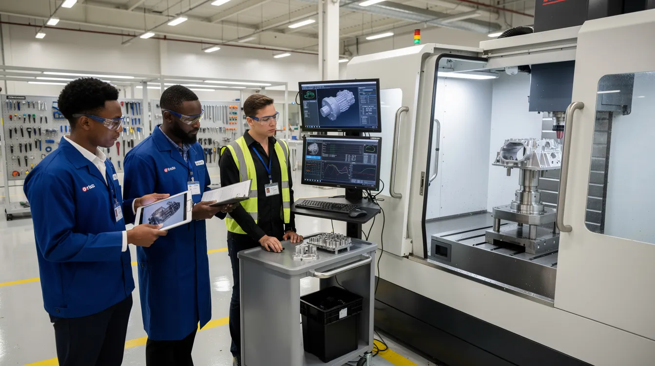
    A cross-functional aerospace quality team is reviewing component inspection results beside a production cell, focusing on implementing corrective and preventive actions as part of their quality management system. They are engaged in root cause analysis to ensure continuous improvement and prevent recurrence of quality defects in the manufacturing process.

    Building the CAPA Action Plan

    The capa plan translates root cause findings into specific action plans. It should separate correction from corrective action. Correction fixes the affected part or record. Corrective action changes the system so the issue does not recur. A preventive action plan extends the lesson to similar risks elsewhere.

    An aerospace CAPA action plan may include:

    • Process changes to routing, inspection sequence, traveler logic, or MRO task flow.
    • Procedure updates and revised digital work instructions.
    • Tooling changes, fixture improvements, calibration frequency changes, or gage updates.
    • Training tied to the revised process, not generic retraining.
    • Supplier development, supplier audits, or updated purchase order quality clauses.
    • Design changes, ECOs, configuration updates, or FAI requirements.
    • Additional controls for detection, such as automated verification, required signoffs, or inspection hold points.

    Every action should have an owner, due date, risk priority, required evidence, and acceptance criteria. The capa owner should not be left to chase status manually through email. Capa management works best when ownership, escalation, and evidence expectations are visible from the start.

    Connect981 provides configurable CAPA forms with action tables, owner assignment, e signatures, due dates, escalation logic, and links to downstream change control and validation activities. This supports implementing corrective actions without losing the connection between the root cause and the work being done.

    Effective CAPA Closure: What “Done” Really Looks Like

    Effective capa closure is not the point where tasks are checked off. It is the point where evidence shows the issue is controlled and unlikely to recur within defined risk limits. That is the difference between activity and control.

    A strong capa program defines closure criteria before closure begins. For example, the organization may require three consecutive production lots with zero repeat defects, 90 days without a similar NCR, a successful internal audit of the revised process, or verified supplier performance after corrective action. The criteria should match the severity and risk of the issue.

    Cosmetic closure is a common failure. A document is updated, a training record is signed, and the CAPA is closed before the production process proves stability. That approach does not satisfy regulatory expectations. It also fails operations because recurrence returns the same problem to the same people weeks later.

    Aerospace teams should use plan do check act thinking. Plan the CAPA, do the implementation, check performance against evidence, and act again if the data shows the fix did not hold. This is where capa effectiveness is proven. Connect981 can automate effectiveness tracking using real production and inspection data, then prompt the capa owner when enough evidence is available for closure review.

    Closure Evidence: Proving the CAPA Worked

    Closure evidence should prove that the action was implemented and that it worked. Auditors and OEM customers are not looking for a clean form. They are looking for evidence of a controlled process.

    Useful closure evidence includes:

    • Before and after trend charts showing reduced defect rate, scrap, rework, or escapes.
    • Zero repeat NCRs for the same issue over a defined time period or production quantity.
    • Successful FAI after a process, tooling, or configuration change.
    • Audit reports confirming that operators are using the revised procedure or work instruction.
    • Approved ECOs, updated drawings, released routers, revised inspection plans, and current digital work instructions.
    • Validated CNC, test rig, inspection, or software program changes where applicable.
    • Training completion records tied to the exact revised process.
    • Supplier performance records showing the same defect has not recurred.
    • Updated FMEA, risk controls, control plans, or inspection frequency.
    • Formal capa review sign off by the quality manager, CAPA board, or authorized approver.

    The CAPA review should confirm that the root cause logic is sound, the risk assessment remains valid, the actions match the cause, and the effectiveness data is sufficient. If the evidence is weak, the CAPA should remain open. If recurrence appears, the team should reopen the investigation or launch a new CAPA with the prior failure included in the analysis.

    Connect981 presents closure packets and dashboards that show timelines, action status, evidence links, trend plots, and approval history. This helps quality leaders verify effectiveness without rebuilding the story from scattered records.

    Integrating CAPA with Change Control, Quality Management, and Suppliers

    CAPA does not operate alone. It is part of quality management, risk management, supplier management, configuration control, and production execution. Many capa actions require formal change control because they affect routers, work instructions, inspection plans, tooling, software, drawings, or maintenance procedures.

    That integration is where many organizations struggle. A CAPA may require an updated work instruction, but the change is released only in a document system and never reaches the station. A supplier may submit a response, but receiving inspection does not change its sampling plan. An engineering change may be approved, but the FAI requirement is missed. These are not individual failures. They are workflow gaps.

    CAPA should connect to:

    • Internal audits and audit finding closure.
    • FAI and production readiness.
    • Configuration management and engineering change control.
    • MRO maintenance records and parts history.
    • Supplier portals, supplier corrective actions, and procurement workflows.
    • Training and qualification management.
    • Management review, especially for repeated or high severity capa trends.

    Connect981 links CAPA to change control workflows, supplier collaboration, and real time shopfloor execution. Approved changes can be pushed to the right workstations, suppliers, and inspection points with revision control. The organization can then show not only that the CAPA was approved, but that the approved process reached the people doing the work.

    Digital CAPA Systems in Aerospace: From Paper to Connected Workflows

    Paper and spreadsheet based CAPA tracking can work for a small volume of simple issues. It breaks down when operations span multiple sites, suppliers, product lines, and regulatory obligations. The problem is not just administration. The problem is weak data continuity.

    An effective capa system gives teams a single source of truth for CAPA documentation, owners, due dates, evidence, approvals, and closure status. It also supports automated reminders, escalations, consistent templates, electronic signatures, and audit ready traceability. In practice, this reduces time spent searching for records and increases time spent solving the actual problem.

    A connected digital system should support:

    • Linked NCR, MRB, containment, CAPA, and closure records.
    • Real time dashboards for open actions, aging, risk level, and overdue items.
    • Cross site capa trends and supplier performance visibility.
    • Configurable capa procedures that reflect the organization’s quality system.
    • AI assisted root cause analysis and production quality insights.
    • Integration with ERP, MES, PLM, QMS, supplier portals, and shopfloor execution.
    • Evidence capture from photos, inspections, calibration records, training, and change approvals.

    Technology does not replace judgment. It helps the organization make good judgment repeatable. Connect981 is built for aerospace manufacturing and MRO teams that need CAPA connected to real work: digital work instructions, quality checks, supplier collaboration, traceability, routing, and compliance records.

    For aerospace manufacturers and MRO providers looking to standardize CAPA, reduce regulatory compliance risk, and close the loop from defect to verified improvement, Connect981 provides a practical path. Request a demo to see how an integrated CAPA workflow can connect NCRs, MRB decisions, root cause analysis, change control, supplier actions, and effectiveness verification in one operational layer.


  • Material Review Board (MRB) in Aerospace – Dispositions, Authority, and Digital Traceability

    Material Review Board (MRB) in Aerospace – Dispositions, Authority, and Digital Traceability

    In aerospace, a small defect can become a large decision. A burr, porosity indication, missing certificate, corrosion finding, or dimensional deviation can affect safety, delivery, cost, and configuration control. That is why mrb aerospace processes need clear authority, disciplined evidence, and traceable execution.

    Overview: What Is an Aerospace Material Review Board (MRB)?

    A material review board is a controlled authority for evaluating nonconforming material, components, assemblies, raw materials, and records. A Material Review Board (MRB) is a cross-functional team that evaluates nonconforming materials to determine their fate, ensuring decisions are based on quality and safety considerations.

    The material review board MRB is not just a meeting held on a weekly or monthly basis. It is a material review board process embedded in daily operations across OEMs, Tier 1 suppliers, and MRO organizations. It connects the non conformity report, concessions, deviations, engineering analysis, production data, and final disposition.

    Do not confuse this with the Maintenance Review Board (MRB), which governs scheduled fleet-wide maintenance standards in aviation, playing a critical role in maintaining airworthiness. The aerospace material review function focuses on product nonconformance and whether the affected item can move forward.

    AS9100 and regulatory expectations require nonconforming product to be identified, reviewed, approved, and documented by authorized personnel. FAA guidance such as FAA Order 8120.23 reinforces the need for defined MRB authority and objective records.

    Connect981 supports this work by tying ERP, MES, QMS, supplier, and shopfloor data into one traceable mrb process, so the current mrb record is not scattered across emails or shared folders.

    A technician is carefully inspecting an aircraft component on a clean shop floor, ensuring adherence to quality assurance standards. This process is part of the material review board (MRB) procedure, where nonconforming materials are evaluated to determine their disposition and prevent future nonconformance.

    Who Sits on the MRB and What Authority Do They Have?

    An MRB must consist of highly specialized subject matter experts, including stress engineers, quality assurance specialists, and design engineers. The board members usually come from different departments because one function rarely has enough context to decide alone.

    Typical roles include:

    • Quality assurance lead or chair: controls the process, verifies containment, ensures records are complete, and confirms the decision follows procedure.
    • Quality engineers: review inspection evidence, defect history, customer requirements, and audit risk.
    • Design engineer: determines whether the condition affects form, fit, function, or approved design intent.
    • Stress or structural engineer: evaluates metal fatigue, stress loads, damage tolerance, residual margin, and primary structure impact.
    • Manufacturing engineer and mrb engineers: define whether repair or rework can be performed with approved resources, tooling, and instructions.
    • Procurement and supplier quality: coordinate vendor communication, supplier corrective action, and return to vendor disposition.
    • Production or MRO operations: explain routing impact, aircraft access, priority, and cycle time constraints.

    Authority is delegated through a charter, quality manual, customer agreement, or engineering authority letter. Local boards may decide minor issues. Major or safety-critical deviations often require OEM, customer, FAA, or EASA approval. MRB teams are responsible for keeping manufacturing and production lines running smoothly while adhering to stringent structural and airworthiness standards, but they must still challenge schedule pressure when conformity or safety is at risk.

    MRB Process Flow: From Detection to Final Disposition

    The MRB process typically begins with the creation of a Nonconformance Report (NCR) when a defect is identified, which is then reviewed by the board to decide on the appropriate disposition of the nonconforming materials.

    1. Detection: issues may come from incoming inspection, in-process checks, NDT, functional test results, final inspection, supplier notice, or MRO discovery.
    2. Containment: parts are quarantined, tagged “HOLD” or “DO NOT USE,” and blocked in ERP, MES, or WMS to prevent shipment or installation.
    3. NCR creation: the condition is described as is, linked to part number, serial or lot, work order, routing, supplier, photos, inspection reports, and test data.
    4. MRB review: board members examine drawings, specifications, process history, prior nonconformance report records, allowable damage limits, and mrb evidence.
    5. Evaluation: the group must determine whether data is sufficient or insufficient, whether extra inspection is needed, and whether the issue can affect aircraft safety.
    6. MRB decision: the board selects a disposition, defines actions, and records who must approve, perform, and verify the work.
    7. Execution and closure: routing, work instructions, reinspection, supplier response, or scrap controls are completed before closure.
    8. Feedback: recurring issues are linked to corrective action to prevent recurrence.

    In Connect981, this flow is captured in one controlled record, visible to quality, engineering, production, procurement, and suppliers.

    Standard MRB Disposition Paths in Aerospace

    Common dispositions made by the MRB include accepting materials as-is, reworking them, returning them to the vendor, or scrapping them if they cannot be corrected. The Material Review Board (MRB) can recommend several dispositions for nonconforming materials, including use as-is, rework, return to vendor, and scrap.

    • Use as is: If the nonconformity does not affect the product’s form, fit, or function, the MRB may decide to accept the item as-is, which is also known as accepting under concession. In aerospace, this requires engineering rationale and, for structural items, stress review.
    • Rework: When a part is found to be defective, the MRB may determine that it can be reworked to meet the original specifications, provided that the costs and time involved do not disrupt the production process. Rework returns the item to drawing compliance.
    • Repair: Repair is an approved deviation from the original design, such as blended damage, bushings, patches, or doublers. Strict regulatory compliance involves ensuring every repair disposition meets airworthiness standards set by authorities like the FAA and EASA.
    • Regrade or downgrade: materials may move to a lower-criticality use only when allowed, relabeled, and configuration records are updated.
    • Return to vendor: In cases where the defects are significant and affect the product’s quality, the MRB may recommend returning the materials to the vendor for corrective action.
    • Scrap: If the defective materials cannot be reworked or returned, the MRB may decide to scrap them, especially if the financial and time loss does not justify rework or return. Scrap must be documented by quantity, serial, and destruction status.

    Every disposition needs rationale, risk level, required follow-up, and approval trace.

    Material Review Board Documentation and Traceability Requirements

    Each mrb record should include NCR number, part number, serial or lot number, work order, affected aircraft or engine registration for MRO, defect description, detection point, responsible organization, drawings, specifications, and revision levels.

    Evidence includes inspection reports, NDT images, measurement data, supplier certificates, photos, test logs, stress calculations, and engineering approvals. Effective MRB practices require that all decisions regarding nonconforming materials are defensible, meaning that the rationale for each decision must be recorded contemporaneously and linked to objective evidence, ensuring compliance with regulatory standards.

    Traceability must run backward to materials, suppliers, processes, and approved data, and forward to affected assemblies, aircraft, customers, and as-maintained configuration.

    Regulatory requirements mandate that nonconformances are investigated, decisions are justified, and records are complete, particularly in industries such as pharmaceuticals and medical devices, which are governed by 21 CFR regulations. The Material Review Board (MRB) process must integrate with quality management systems to ensure that all decisions regarding nonconforming materials are documented with objective evidence, including e-signatures and secure audit trails, as required by regulations like Part 11 and Annex 11.

    Compliance gaps can arise when MRB documentation is inconsistent, leading to audits being complicated by missing approvals or unclear records.

    Integration of MRB with NCR, CAPA, and Change Management

    MRB is part of the broader quality system, not a separate island. NCRs identify and document the condition. MRB decides the disposition. CAPA addresses why the issue happened and how to prevent recurrence.

    MRB teams contribute to aviation safety by maintaining structural integrity and preventing future failures through root cause analysis. Repeated material review cases may trigger supplier 8D, process changes, updated inspection plans, or engineering change notices. If the same deviation is discussed every monthly basis, the issue is no longer just an MRB workload problem. It is a system signal.

    Connect981 links NCR, MRB, CAPA, and change workflows so leaders can see whether corrective action reduces future risk.

    Digital MRB in Practice: Making Decisions Enforceable and Audit-Ready

    Disconnected data and documentation can slow down MRB processes, as many reviews still rely on spreadsheets or shared folders, leading to confusion about the most current information. Manual routing and follow-up can stall MRB processes, as reliance on people passing forms or forwarding emails can lead to delays if someone is unavailable.

    Digital MRB changes the control point. On-hold parts cannot be issued, installed, or shipped until an approved mrb decision is complete. Role-based access ensures only authorized board members approve dispositions. E-signatures, timestamps, and revision history create the audit trail.

    Limited visibility into patterns of nonconformance can hinder MRB effectiveness, as data scattered across drives makes it difficult to identify recurring issues before they escalate. Dashboards for open cases, scrap value, supplier trends, and cycle time help most manufacturers focus improvement work where it matters.

    An engineer is using a tablet while standing beside various aircraft parts in a maintenance bay, engaging in the material review board process to assess the quality of components. This setting highlights the collaboration of quality engineers and cross-functional teams in managing nonconforming materials and ensuring safety in aerospace operations.

    Examples of Nonconforming Materials and MRB Review Scenarios

    • Machined structural bracket: A hole is 0.020 inch out of tolerance. MRB teams analyze the damage to aircraft parts to understand its nature and extent, focusing on factors such as metal fatigue and stress loads. Stress may approve use as is with serial-specific traceability.
    • Composite panel: NDI finds local porosity or ply misalignment. If allowable limits and margins support repair, an approved scheme is issued. If not, scrap is required.
    • MRO corrosion finding: Corrosion on a wing skin panel is reviewed against OEM repair data and EASA expectations. The repair, inspections, and release records stay linked.
    • Supplier fastener issue: Oversize holes appear across lots. MRB may initially approve rework or repair, then escalate to CAPA when trend data shows recurring supplier risk.

    Best Practices for a Robust Aerospace MRB Process

    • Define written authority, escalation rules, disposition categories, and risk thresholds.
    • Use standardized digital templates for every review and attachment.
    • Train mrb engineers, quality assurance, and board members regularly on AS9100, customer rules, and lessons learned.
    • Keep independence clear. Safety and conformity outrank schedule pressure.
    • Track metrics such as weekly backlog, cycle time, scrap cost, and repeat defects.
    • Link outcomes to work instructions, supplier collaboration, and future process improvements.
    • Treat objective evidence as a best practice, not an audit afterthought.

    How Connect981 Helps Standardize and Scale MRB in Aerospace Organizations

    Connect981 is an aerospace operations platform that unifies NCRs, MRB decisions, CAPA, routing, supplier workflows, and work execution on top of existing ERP, MES, PLM, and QMS systems.

    Zero and low-code tools let quality and manufacturing engineers configure approvals, notifications, and templates without a long IT project. Digital work instructions execute rework and repair consistently, while results and signoffs are captured at the point of work.

    For teams modernizing mrb aerospace processes, the goal is practical: stronger disposition control, clearer decision authority, and audit-ready traceability. Request a Connect981 demo to see how your MRB workflow can be standardized across sites and suppliers.

  • What is electronic work instruction?

    Electronic work instructions (EWIs) are digitally delivered work instructions that guide operators, technicians, and inspectors through a manufacturing or maintenance task. Instead of static paper documents, EWIs are created, maintained, and executed in software, typically tying the instruction content to part numbers, routings, revisions, and specific equipment or workstations.

    What makes a work instruction “electronic”?

    In this context, “electronic” means that the instruction is:

    • Authored and maintained in a digital system rather than as standalone documents.
    • Delivered to the point of use on a screen (PC, tablet, HMI, or smart tool) instead of printed binders.
    • Linked to structured data such as BOMs, routings, NC programs, tooling lists, quality plans, or inspection points.
    • Version-controlled so that the system can enforce which revision applies to which job, part, or serial number.
    • Capable of capturing execution data (who did what, when, and in what sequence) as part of the production record.

    Typical capabilities of electronic work instructions

    Depending on the system and integration level, EWIs may support:

    • Step-by-step task guidance with required fields, checkboxes, and confirmations.
    • Embedded visuals such as drawings, 3D models, photos, and short videos.
    • Configurable logic (e.g., branching steps based on model variant, options, or test results).
    • In-line specification checks, torque values, key characteristics, or inspection criteria.
    • Electronic signatures, role-based approvals, and audit trails for changes.
    • Automatic data capture from tools, gauges, or test equipment where integrations exist.
    • Traceability links between the instruction followed and the resulting lot, serial, or batch record.

    How EWIs fit in a brownfield, regulated environment

    In most regulated plants, EWIs do not completely replace existing systems. They usually coexist with and integrate to:

    • MES/ERP for work orders, routings, scheduling, and labor reporting.
    • PLM/PDM for engineering source of truth, CAD, and change management.
    • QMS/EDMS for controlled procedures, records, and formal approvals.

    In these environments, EWIs typically act as the execution layer that operationalizes engineering intent on the shop floor. The work instruction content may be derived from PLM or controlled documents, while MES or ERP determines which instruction version is needed for a specific job. A full replacement of MES or PLM with an EWI tool alone is rarely practical in aerospace-grade or similar contexts due to validation burden, qualification of interfaces, downtime risk, and the need to maintain long-term traceability.

    Constraints, dependencies, and risks

    The actual benefit and reliability of EWIs depend heavily on:

    • Integration quality: Poor or missing integration with MES, PLM, QMS, or tool data can cause version mismatches, duplicate data entry, or incorrect instructions at the workstation.
    • Governance and change control: Without clear ownership and a controlled change process, EWIs can diverge from approved procedures or design authority, creating audit and safety risk.
    • Validation and qualification: In regulated industries, EWI systems and key integrations often require validation or qualification. Skipping this or doing it superficially increases compliance risk.
    • Device and infrastructure reliability: Network outages, aging HMIs, or shared terminals can block access to instructions or encourage local workarounds like screenshots or printed copies.
    • Content quality and usability: Poorly designed electronic instructions (overloaded screens, unclear steps, slow navigation) can increase errors even if the system is technically robust.

    EWIs do not themselves guarantee compliance, mistake-proofing, or efficiency. They are one component in a broader system that includes procedures, training, tooling, maintenance, and quality controls.

    Common tradeoffs when moving from paper to EWI

    When transitioning from paper-based instructions to EWIs, organizations typically face tradeoffs such as:

    • Speed vs. rigor: Rapid rollout of digital instructions can conflict with the need for thorough review, testing, and validation.
    • Standardization vs. flexibility: Highly standardized templates improve consistency but may not fit all product variants or legacy processes without rework.
    • Central control vs. shop-floor agility: Tight central control improves auditability but can slow down legitimate local improvements if change channels are not streamlined.
    • Incremental coexistence vs. full replacement: Phased adoption (keeping some paper or legacy screens) reduces risk but increases complexity and potential confusion during the transition.

    When are electronic work instructions useful?

    EWIs are typically most valuable when you need to:

    • Improve consistency and reduce variability in multi-step, human-centric operations.
    • Manage high product mix or frequent design changes where paper updates lag.
    • Strengthen traceability of who performed which step, using which revision, on which serial or lot.
    • Embed in-process quality checks and data capture directly into the work sequence.
    • Support newer or rotating workforce with clearer guidance and visuals.

    In all cases, the effectiveness of EWIs depends on the underlying process maturity, system integrations, and governance. Treat them as an execution and data-capture layer that must align with existing MES, PLM, and QMS rather than as a standalone solution that replaces everything else.

  • Andon System Manufacturing: From Cords and Lights to Digital Escalation Workflows

    Andon System Manufacturing: From Cords and Lights to Digital Escalation Workflows

    Key Takeaways

    • An andon system is a structured escalation process, not just a light, board, or andon cord.
    • Andon in lean manufacturing still matters because it creates faster response, fewer defects, less downtime, and better visibility.
    • Modern digital andon systems connect alerts to corrective actions, root cause analysis, dashboards, and continuous improvement.
    • Connect 981 supports andon-style workflows inside a broader aerospace and MRO operations platform, not as a standalone andon light system.

    Introduction: Why Andon System Manufacturing Still Matters in 2026

    In 2026, many production problems still start small. A machinist sees a dimension drifting on an aerospace component. An electronics operator detects a missing connector before test. An MRO technician opens an engine module and finds the routing sheet does not match the installed configuration. If the issue is not surfaced quickly, hours of rework, scrap, schedule disruption, and audit exposure follow.

    Unplanned downtime commonly consumes 5 to 20 percent of productive capacity in manufacturing, according to Monitory.ai research on downtime cost. In regulated industries like aerospace, the cost is not only lost production time. A single escaped defect can trigger NCRs, MRB review, customer notification, and late delivery penalties.

    That is why andon system manufacturing remains relevant in high-mix, high-variance environments such as aerospace structures, avionics, precision machining, and MRO. This article treats the andon system as a structured escalation mechanism: signal, ownership, response, resolution, and learning.

    Traditional Andon systems typically rely on physical components such as pull cords, lights, and manual boards to signal issues, while digital Andon systems integrate with software and IoT technologies for real-time monitoring and alerts. The best implementations connect MES, ERP, quality records, supplier workflows, and continuous improvement efforts.

    A factory operator is using a tablet beside an aircraft assembly fixture, actively engaging in the production process while utilizing a digital andon system for quality control and operational excellence. The setup highlights the integration of modern andon systems in lean manufacturing, enhancing problem detection and rapid response capabilities on the production floor.

    What Is an Andon System in Manufacturing?

    An andon system is a visual and audible alert and escalation mechanism that surfaces abnormalities in real time. The japanese word “andon” originally referred to a lantern, which is why the concept became closely associated with visual management.

    Its roots are in lean manufacturing and the toyota production system, especially jidoka: build in quality and stop to fix when an abnormality occurs. In Toyota’s production system, the Andon cord allows any assembly employee to pause production when quality issues arise, ensuring defects do not propagate down the line.

    A good andon process replaces shouting, radios, sticky notes, and tribal knowledge with standardized andon signals. Operators, line workers, team leader roles, maintenance technicians, quality engineers, logistics, safety, engineering, and production control all know what happens next.

    The andon system works through a simple flow: problem detection, andon alert, owner assignment, corrective actions, closure, and data logging. The primary benefits of an Andon system include reduced downtime, empowered workers, higher quality control, and data-driven process improvements.

    How an Andon System Works on the Shop Floor

    An Andon system operates through a precise process flow designed for rapid response, allowing operators to signal issues immediately when they occur. Andon systems enable immediate problem detection, allowing workers to quickly identify and report issues without leaving their workstations, which results in reduced downtime and improved productivity.

    A trigger may be an andon cord pull, push button, HMI soft button, barcode scan, QR scan, automatic andon from sensors or PLCs, or software-triggered digital alerts. In a mature system, the andon alert includes location, issue type, severity, timing, product, and work order.

    In the first five minutes, the team acknowledges the alert notification, triages at the station, decides whether to stop production, and applies containment or a temporary countermeasure. If the line stops, restart criteria should be explicit. Every event should be timestamped, categorized, and tied to a job, serial, or work order.

    Core Components: Cords, Lights, Boards, and Digital Andon

    The classic Andon system consists of three primary components: the Andon cord, Andon light, and Andon board, which work together to signal issues on the production floor. Andon systems typically consist of three primary components: an Andon cord, an Andon light, and an Andon board, which work together to alert team members about production issues.

    Traditional Andon Cords and Fixed-Position Stop

    Traditional andon on final assembly lines often used an overhead andon board and overhead pull cord. The Andon cord is typically located overhead on the assembly line and can be pulled by operators to signal that assistance is needed due to a problem identified in the production process.

    When an operator pulls the cord on a manufacturing line, a timed response window starts. If the issue is not resolved, the product stops at a predefined station. In a fuselage section, for example, mis-torqued fasteners must be corrected before the body moves to the next dock. This balances flow protection with product quality protection.

    Andon Lights, Buzzers, and Local Signals

    Stack lights, buzzers, audio alerts, and visual cues provide immediate local feedback. Andon lights use a color-coded system to indicate the status of production: green for normal operation, yellow for a minor issue that needs attention, and red for a stop condition requiring immediate investigation.

    The Andon light system uses color coding to indicate different statuses: green for normal operation, yellow for minor issues needing attention, and red for serious problems requiring immediate action. Color-coded lights and auditory tones are typically used in Andon systems to denote production status and operational bottlenecks.

    Local signals are useful, but support teams may miss them in large plants, noisy areas, or dense layouts. A light alone does not prove who responded, when they arrived, or whether the root cause was removed.

    Andon Boards and Plant-Wide Visibility

    Andon boards serve as centralized visual control centers that display the status of production lines, allowing supervisors and team members to quickly assess operational conditions and respond accordingly. Andon boards serve as centralized visual control centers that display the status of production lines, allowing supervisors and team members to monitor operations at a glance.

    Traditional andon boards used physical lights, tags, or scoreboards. Digital boards now show line status, downtime reasons, response timers, production targets, production metrics, and open escalation paths across the plant floor.

    From Physical Andon to Digital Andon Systems

    A digital andon system combines physical signals with andon software, mobile notifications, IIoT sensors, and role-based workflows. Digital Andon systems enhance the traditional approach by providing automated alerts, real-time data integration, and customizable dashboards, which allow for faster response times and better tracking of production issues.

    In modern Andon systems, digital boards can integrate with factory systems to provide real-time data visualization, showing key performance indicators and alerts for immediate action. Digital Andon systems enhance traditional setups by integrating with other manufacturing software, providing real-time data visualization and automated alerts to improve response times.

    Why Andon Matters in Lean Manufacturing and Aerospace Operations

    Andon systems are integral to Lean manufacturing as they provide immediate visual alerts to operators and management about production issues, enabling quick responses to prevent defects from propagating down the line. As a lean tool, andon supports flow, respect for people, quality assurance, and the lean principle of stopping to fix.

    The implementation of Andon systems supports the Lean principle of continuous improvement (Kaizen) by allowing workers to identify and address problems as they occur, thus reducing waste and enhancing product quality. Andon systems support continuous improvement (Kaizen) by helping identify frequent stumbling blocks in the production process, which can lead to targeted improvements.

    Andon systems help minimize defects by catching errors at the source, saving time, reducing material waste, and lowering rework costs. By addressing issues as they occur, Andon systems help ensure that resources are used efficiently and only high-quality products continue through the production line, leading to scrap reduction.

    Andon systems empower employees by allowing them to stop production when they detect a quality issue, fostering a culture of accountability and teamwork focused on quality and efficiency. Implementing Andon systems empowers employees by allowing them to stop the production line if they detect a quality issue, promoting a culture of quality and accountability.

    For aerospace and MRO, this matters because traceability, AS9100, FAA, EASA, ITAR, configuration control, and quality standards create a higher cost of late detection. Andon systems provide real-time visibility into the manufacturing process, enabling teams to identify and resolve floor abnormalities before they escalate.

    Traditional Andon vs. Digital Andon: What’s Really Different?

    Most plants do not choose between physical and digital. They blend both. The real shift is from “signal only” to “signal plus response management and learning.”

    Traditional Andon: Fast Signal, Limited Follow-Through

    While traditional Andon systems provide immediate visual signals, they often lack the ability to track response times and issue resolution, whereas digital Andon systems can log incidents, assign tasks, and escalate alerts automatically.

    A torque wrench failure may trigger an andon signal. Maintenance arrives late, the tool is swapped, and production resumes. If duration, cause, and corrective actions are not recorded, the same issue repeats across shifts.

    Digital Andon: From Alert to Resolution Management

    Digital systems convert an alert into a structured event with line, station, product, shift, category, severity, and timestamps. Digitally driven Andon systems can track downtime patterns and recurring issues, providing actionable data for long-term process optimization.

    Modern Andon systems log the frequency and duration of stops to help managers track long-term bottlenecks. If no one acknowledges an alert within the defined time, escalation moves to supervisors, value stream managers, or plant leadership.

    Hybrid Approaches: Lights on the Line, Software in the Background

    A strong hybrid approach keeps the operator interface simple. A button press at a CNC cell can change stack lights, log the event, and notify maintenance through mobile notifications. This preserves quick response while adding traceability, accountability, and data for reducing waste.

    What Problems Does an Andon System Signal? Practical Shopfloor Examples

    Andon alerts should focus on problems that affect flow, safety, quality, delivery, or compliance. Common categories include machine downtime, quality issues, material shortage, supplier part issue, tooling, calibration, documentation, safety concern, and production bottleneck.

    Machine Downtime and Equipment Failures

    A CNC spindle alarm, hydraulic leak, or oven temperature deviation should trigger an andon alert. Maintenance technicians receive the alert, line status changes, and the timer starts. Capture machine ID, fault code, duration, spare parts used, root cause, and corrective actions.

    Quality Defects and Escaped Issues

    A dimensional nonconformance or wiring error should route to quality engineers. The area may contain suspect product, pause the station, or stop production if the defect could move downstream. Link the event to NCR, MRB, 8D, lot, and serial records.

    Material Shortages and Supplier Part Issues

    If a kitting area lacks a bracket or a supplier seal fails incoming inspection, the alert should go to materials, procurement, and planning. Capture part number, supplier, required quantity, PO, work order, and schedule impact.

    Tooling, Fixtures, and Calibration Problems

    A worn cutting tool, fixture misalignment, or expired gauge can create quiet quality drift. The andon system gives operators permission to call for help before bad parts accumulate. Tracking these events improves tool change intervals, poka-yoke, and standard work.

    Documentation, Work Instructions, and Missing Information

    Outdated drawings, unclear digital work instructions, or missing customer addenda are legitimate andon events. Operators should not build to guesswork. Digital andon connects the issue to the exact work order, revision, operation, and owner.

    Safety Concerns and Near Misses

    Coolant on a walkway, missing guarding, or incorrect PPE should trigger stricter rules. Safety alerts often require immediate stop, EHS involvement, photos, contributing factors, and preventive action.

    Production Bottlenecks and Operator Assistance

    Not every alert means the line stops. Assistance calls help team leaders rebalance labor, support training, and identify unstable work. Separate assistance KPIs from hard stops so line workers keep raising issues when problems arise.

    Issue Categories, Response Rules, and Accountability

    Categorization turns lights and noise into a management system. Plants should define stable categories such as quality, machine, material, safety, documentation, methods, and staffing.

    Each category needs a default owner, response expectation, and restart rule. Quality may require containment. Machine faults may require lockout or maintenance triage. Supplier problems may require buyer escalation. Digital systems can enforce role-based ownership so issues arise, move, and close with named accountability.

    Andon as a Continuous Improvement Engine, Not Just an Alarm

    The value of andon is not only faster firefighting. It is the learning loop. Frequency, duration, category, root cause, area, and shift data feed Pareto charts, A3 reviews, kaizen events, and continuous improvement priorities.

    Andon systems foster better communication between workers and management, ensuring that alerts can be acted upon swiftly, which enhances overall operational efficiency. Weekly reviews can expose chronic supplier shortages, repeated sensor failures, unclear work instructions, and gaps in robust processes.

    Common Andon Implementation Mistakes (and How to Avoid Them)

    Many plants install lights and cords but never achieve operational excellence because the process is weak. Common mistakes include treating andon as hardware only, unclear rules, slow response, blame culture, excessive categories, and poor data capture.

    3M and Caterpillar utilize button-based Andon systems where operators can signal issues, prompting immediate attention from team leaders to resolve problems quickly. Amazon employs a “Virtual Andon Cord” in its customer service operations, allowing representatives to trigger alerts for significant product issues, potentially halting shipments until the root cause is addressed. In healthcare, Andon principles are applied to improve patient safety, such as using lights on Code Blue carts to signal daily checks and alarms on infusion pumps to alert staff about potential issues.

    Slow Response Times and Missing Escalation

    If no one responds, operators stop using the system. Define expectations, such as two to three minutes for acknowledgement and a severity-based target for first action. Use andon boards or dashboards to show open alerts and timers.

    Unclear Ownership and Fragmented Follow-Up

    “Maintenance will handle it” is not ownership. Assign a role or named owner for each alert, require handoffs, and prevent closure without verified corrective actions.

    Weak Data Capture and Inconsistent Classification

    Paper logs and retrospective spreadsheets are late, incomplete, and hard to analyze. Use simple digital forms with picklists, photos, cause codes, and periodic data quality audits.

    Designing an Andon Workflow: Practical Checklist

    Use this checklist when implementing andon or upgrading a lean manufacturing system.

    Checklist Items: From Trigger to Trend Review

    • Who can trigger an andon alert? Operators, inspectors, maintenance, team leaders, and any person for safety or quality concerns.
    • How is the alert triggered? Andon cord, push button, stack light, tablet, HMI, QR code, sensor, PLC, or automatic andon.
    • What happens immediately? Acknowledge, triage, contain, decide whether the line stops, and communicate status.
    • Who owns the response? Assign default owners by category and escalation paths when the issue is not resolved.
    • What data is captured? Station, machine, product, batch, serial, shift, severity, timestamps, photos, root cause, and action.
    • How is the issue closed? Require verification, documented corrective actions, and restart approval when needed.
    • How are trends reviewed? Use weekly or monthly reviews of dashboards, production metrics, repeat issues, and top loss drivers.
    • How should rollout begin? Pilot one line or cell, refine with operators, then scale across the plant.

    A maintenance technician is inspecting a machine tool on the production floor, with a nearby signal light indicating the status of the andon system. This visual management tool helps alert operators to any quality control issues or abnormalities that may arise during the production process.

    Digital Andon Systems and Workflow-Based Escalation

    Modern andon systems increasingly sit inside broader digital operations platforms. The digital andon system integrates with MES, ERP, CMMS, QMS, PLM, and supplier systems to create a unified view of production, quality, and maintenance.

    In a high-tech electronics assembly line, an automatic Andon system uses sensors to detect assembly errors and equipment malfunctions, triggering visual alerts on digital dashboards and notifications to maintenance teams. This is where digital tools matter: alerts become tasks, approvals, and records instead of isolated messages.

    Andon Software Capabilities to Look For

    Look for configurable alert types, routing rules, multi-channel notifications, timed escalation, structured forms, photo uploads, links to work orders, links to defect records, audit logs, digital boards, OEE dashboards, and APIs. Configurability is critical because new products, regulations, and routings change faster than traditional IT projects.

    How Connect 981 Supports Andon-Style Escalation in Aerospace and MRO

    Connect 981 is a unified aerospace operations platform that can support andon-style escalation as part of broader production, quality, supplier, and MRO workflows. It is not an andon light system. It is an operations layer that connects alerts with work instructions, traceability, defects, supplier collaboration, and compliance records.

    From Andon Alert to Structured Workflow

    An operator or inspector can raise an alert from a tablet form tied to a work step. Connect 981 can route the event to quality, maintenance, methods, supply chain, or program teams based on line, category, customer, or severity. Status changes such as raised, acknowledged, blocked, resolved, and verified are timestamped.

    Connecting Andon to Work Instructions, Quality, and Traceability

    Connect 981 links events to digital work instructions, drawing revisions, inspection plans, serial numbers, lot numbers, and configuration records. This prevents a common failure mode: the alert lives in one system while the quality record, maintenance action, and supplier response live elsewhere.

    Cross-Factory and Supplier Visibility

    Aerospace primes and tier suppliers often need shared visibility when a supplier issue threatens schedule or conformity. Connect 981 can support cross-factory comparison of alert frequency, response times, issue types, and supplier nonconformance patterns.

    A group of aerospace technicians is gathered on a clean shop floor, closely reviewing a critical component as part of their quality control process. The environment reflects lean manufacturing principles, emphasizing operational excellence and continuous improvement efforts in their production line.

    Why Zero/Low-Code Matters for Andon Workflows

    Aerospace and MRO operations change frequently. New programs, customer requirements, inspection steps, and supplier rules require adaptable workflows. Connect 981’s zero and low-code workflow builder helps operations and CI teams adjust categories, forms, routing, and escalation without long custom development cycles.

    Conclusion: Build an Andon System That Turns Problems Into Progress

    An effective andon system is a structured escalation process that spans signal, alert, response, verification, and learning. Traditional cords, stack lights, and boards still have value, but they deliver more when connected to workflows, data capture, and accountability.

    The practical question is direct: are problems visible, are responses reliable, and does event data drive improvement? If not, the system is signaling, but it is not yet learning.

    Request a demo to see how Connect 981 turns shopfloor issues into structured workflows, traceable actions, and production visibility across aerospace manufacturing and MRO.

    FAQ

    How big should we start when implementing or upgrading an Andon system?

    Start with one production line, cell, or value stream. Use three to five categories, simple response rules, and a 60 to 90 day pilot. Include operators, maintenance, quality, and team leaders from day one.

    Do we need new hardware to move to a digital Andon system?

    Not always. Existing stack lights, buttons, PLC inputs, and HMIs can often connect through gateways or APIs. In many cases, the bigger change is process discipline, not hardware replacement.

    How do we prevent operators from overusing the Andon system and slowing production?

    Define severity levels and clear examples. A safety concern, quality risk, sustained equipment issue, or missing critical information should be raised early. Minor help calls should be tracked separately from hard stops.

    How does an Andon system fit with our existing MES or ERP?

    Andon complements MES and ERP by handling real-time exceptions around the execution data those systems manage. Platforms like Connect 981 can sit above existing systems as a unified operations layer.

    What metrics should we use to measure Andon system effectiveness?

    Track alerts by category, average response time, average resolution time, repeat issue rate, downtime minutes, scrap, rework, and production impact. Review these metrics in tiered meetings and CI reviews, not only on dashboards.

  • What are common hybrid architectures for aerospace MES?

    Common hybrid architectures for aerospace MES usually combine existing ERP, PLM, QMS, maintenance, and sometimes legacy MES systems with newer execution, traceability, integration, or analytics layers. Full replacement is often unrealistic in aerospace-grade environments because qualification burden, validation cost, downtime risk, integration complexity, traceability obligations, change control, and long equipment lifecycles can outweigh the theoretical simplicity of a clean cutover.

    The practical question is usually not whether to replace everything. It is which execution functions must be controlled directly by MES, which systems remain authoritative, and how records, revisions, exceptions, and approvals move across the architecture without breaking evidence trails.

    Common hybrid patterns

    • MES as an execution layer over ERP and PLM. ERP remains the system of record for orders, inventory, costing, and planning. PLM remains authoritative for engineering definitions, bills of material, drawings, and revisions. MES controls shop-floor execution, routing status, labor capture, serialized genealogy, work instructions, and production records.
    • Digital traveler and work instruction layer beside legacy MES. A newer system may manage operator guidance, buyoff, defect capture, and electronic records while an older MES continues to handle dispatching, labor, or WIP transactions. This is common when the legacy system is deeply integrated but weak in user experience, version control, or evidence collection.
    • Plant-local execution with enterprise visibility. Plants keep local MES instances or site-specific execution tools, while an enterprise layer aggregates status, quality signals, genealogy summaries, and performance metrics. This can reduce standardization risk, but it requires disciplined data mapping and agreement on common identifiers.
    • Cloud plus edge architecture. Cloud services may provide work instruction management, analytics, supplier collaboration, or multi-site reporting, while edge or plant-local services handle machine connectivity, offline execution needs, latency-sensitive operations, and continuity during network disruption. Suitability depends on cybersecurity, export control, customer flow-downs, and validation strategy.
    • Integration hub or event-driven architecture. Middleware, APIs, message queues, or an integration platform connect MES with ERP, PLM, QMS, metrology systems, maintenance systems, and data historians. This can reduce point-to-point fragility, but it does not solve poor master data, unclear ownership, or inconsistent process definitions.
    • Specialized quality systems alongside MES. FAI, NCR, MRB, CAPA, calibration, inspection, and supplier quality workflows may remain in dedicated QMS or quality tools. MES then exchanges inspection status, nonconformance holds, dispositions, and release signals rather than trying to own every quality process.
    • Supplier and outside-processing portals. Some architectures extend limited execution or status capture to suppliers, processors, or MRO partners. These models need careful control of technical data, revision visibility, acceptance criteria, and evidence returned to the prime or tier supplier.

    What usually determines the right pattern

    The architecture depends on where the authoritative data lives, how mature the current processes are, and how much change the plant can safely absorb. A site with stable routings, clean part and serial structures, and disciplined revision control can support tighter integration. A site with inconsistent master data or informal workarounds usually needs process cleanup before deep automation.

    Program and customer requirements also matter. Defense work, export-controlled data, customer-mandated portals, long-running contracts, and frozen baselines can limit what can be moved, where it can be hosted, and how quickly workflows can change. These constraints are not just IT preferences; they often affect validation, access control, audit evidence, and contract compliance obligations.

    Common failure modes

    • Unclear system of record decisions. If ERP, MES, PLM, and QMS all appear to own part revision, routing, inspection status, or nonconformance state, reconciliation becomes a permanent operating burden.
    • Digitizing undocumented variation. Hybrid MES projects fail when they automate local exceptions without deciding which exceptions are legitimate, controlled, and repeatable.
    • Weak integration testing. Aerospace execution depends on sequencing, holds, approvals, effectivity, and traceability. Basic interface testing is not enough if exception paths are not validated.
    • Broken genealogy or evidence chains. Moving work between systems can create gaps in serial genealogy, material traceability, operator certification records, inspection evidence, or revision history.
    • Underestimated change control. Even small changes to electronic travelers, data capture, integrations, or approval workflows may require documented review, validation, training, and controlled rollout.

    Practical boundary

    A hybrid aerospace MES architecture can be a sound approach, but only if coexistence is designed intentionally. It needs defined ownership of data, controlled integrations, tested exception handling, cybersecurity review, validation evidence, and operating procedures for outages or manual recovery. Without those controls, hybrid architecture becomes another layer of integration debt rather than a safer modernization path.

  • What is the best way to connect PLM changes into MES work instructions?

    The best way is usually a controlled release pipeline, not a raw direct sync. In most regulated manufacturing environments, PLM should remain the system of record for approved product definition, while MES controls execution-ready work instructions, routing context, operator prompts, and evidence capture. PLM changes should flow into MES through a governed transformation and approval process with versioning, effectivity, and traceability. If you let PLM changes overwrite MES instructions automatically, you usually create audit, validation, and shop-floor risk faster than you remove manual work.

    What commonly works

    A practical pattern is:

    1. Approve the engineering change in PLM.
    2. Publish only the data MES actually needs, such as revision, BOM or MBOM elements, process plan references, characteristics, media, and effectivity rules.
    3. Transform that data into MES instruction objects using an integration layer or middleware, not point-to-point logic buried in either system.
    4. Route the MES-side change through operations and quality review where required.
    5. Release the new instruction version with clear effectivity by part, serial, lot, work order, date, or program.
    6. Retire or supersede prior versions without breaking historical as-built records.

    That separation matters because PLM data is often too abstract, too engineering-centric, or too incomplete for direct use on the shop floor. MES work instructions usually need local sequence logic, machine or tooling context, data collection steps, hold points, signoffs, training constraints, and exception handling that do not live cleanly in PLM.

    Do not assume one system should own everything

    No single ownership model works everywhere. Some sites keep most instruction authoring in PLM and push rendered content to MES. Others maintain core process content in MES and consume only controlled design and process references from PLM. In brownfield plants, the second model is often more realistic because legacy MES, ERP, QMS, and document control systems already carry parts of the execution record.

    A full replacement of existing instruction, document, or MES logic is often unrealistic in regulated environments. Qualification burden, validation cost, downtime risk, integration complexity, and long asset lifecycles usually force a coexistence model instead.

    What must be defined up front

    If these are unclear, the integration will become fragile:

    • System of record by object: drawing, specification, MBOM, routing, operation text, media, quality characteristics, limits, training requirement, and signoff rule.
    • Change trigger: ECO, MCO, document release, process plan release, deviation, concession, or temporary instruction.
    • Effectivity logic: when the new instruction applies and what happens to in-flight orders.
    • Approval model: whether operations, quality, manufacturing engineering, and document control must approve the MES-rendered instruction.
    • Version relationship: how a PLM revision maps to one or more MES instruction versions.
    • Exception path: how urgent corrections, redlines, NCR-driven containment, or customer-directed changes are handled.

    If you skip these decisions, you do not get a digital thread. You get conflicting revisions and manual workarounds with better labels.

    Data model matters more than the connector

    The hard part is usually semantic, not technical transport. PLM structures product and engineering intent. MES structures execution steps and data capture. If operation names, work centers, units of measure, characteristic identifiers, and revision rules are inconsistent, the integration will produce ambiguous or unusable instructions.

    That is why a canonical data model, or at least a controlled mapping layer, matters. You need stable identifiers and explicit mappings for:

    • part and revision
    • BOM and MBOM relationships
    • routing and operation sequence
    • inspection characteristics and limits
    • tooling, fixtures, and equipment references
    • attached media and controlled documents
    • effectivity and disposition rules

    Without that, every change becomes a custom integration event.

    Where integrations usually fail

    Common failure modes include:

    • Uncontrolled overwrites: a PLM update replaces MES work content already adapted for plant-specific execution needs.
    • Missing effectivity: the new instruction reaches some orders or stations but not others.
    • Broken traceability: the plant cannot prove which instruction version was used for a serialized build.
    • Poor document rendering: CAD-derived or PLM-authored content is technically correct but unusable by operators.
    • In-flight order confusion: work starts under one revision and completes under another without controlled disposition.
    • Manual side channels: supervisors distribute PDFs, emails, or marked-up screenshots because the formal flow is too slow.
    • Validation gaps: interfaces change, but test scripts, approved workflows, and training records do not.

    These are not edge cases. They are typical when teams treat PLM-to-MES as a simple document sync.

    How QMS and ERP usually fit

    QMS often governs document control, deviations, CAPA links, and training impacts. ERP often governs item, revision, and work order context. MES sits in the middle of execution. If PLM changes alter routings, inspection points, or material consumption logic, the impact may need to be reflected across all three.

    For example, a design change may require:

    • new or revised controlled documents in PLM or document control
    • updated work instruction and data collection logic in MES
    • item or revision updates in ERP
    • inspection plan or nonconformance workflow changes in QMS
    • retraining or qualification checks before operators can execute the new process

    If those dependencies are not coordinated, the instruction update may be technically deployed but operationally blocked.

    What to automate and what to keep controlled

    Automate the transport, mapping, and pre-population of instruction content where the source data is stable and validated. Keep human review where operator usability, quality requirements, or plant-specific execution logic are involved. In regulated settings, fully unattended instruction release is often not appropriate unless the scope is narrow and the controls are mature.

    A good rule is to automate the repeatable translation, not the accountability. Someone still needs to own review, effectivity, and release decisions.

    Practical recommendation

    If you are starting from scratch, aim for event-driven integration with explicit versioning and a review gate on the MES side. If you are in a brownfield environment, start with a narrower scope:

    • one product family
    • one change type, such as released process plan updates
    • one instruction template structure
    • clear effectivity rules
    • traceable links back to PLM change objects

    Prove that you can preserve as-built history, handle in-flight orders, and avoid uncontrolled document drift before expanding scope.

    So the best way is not “connect PLM directly to MES work instructions” as if they are the same object. It is to define ownership, map data intentionally, apply controlled release, and preserve traceability across revisions. The exact design depends on your MES capabilities, PLM structure, validation posture, and how much brownfield integration debt you already carry.

  • Manufacturing Data Historian: From Time‑Series Storage to Connected Aerospace Operations

    Manufacturing Data Historian: From Time‑Series Storage to Connected Aerospace Operations

    Most aerospace factories do not lack data. They lack a reliable way to connect machine evidence to work orders, serial numbers, quality decisions, supplier records, and audit history.

    A manufacturing data historian solves the first part of that problem: capturing what happened in the plant, when it happened, and under what process conditions. The larger operational challenge is making that historian data usable by the teams making daily production, maintenance, and compliance decisions.

    Answering the Core Question: What Is a Manufacturing Data Historian?

    A manufacturing data historian is specialized software for capturing, storing, and retrieving timestamped time series data from industrial equipment, PLCs, sensors, test stands, process controls, and industrial control systems. Data historian software is specifically designed to capture, store, and manage vast quantities of time-series data generated by industrial processes, providing real-time visibility into operations and a centralized repository for operational data.

    Historians emerged in the late 1980s and early 1990s to manage continuous data generated by SCADA, PLCs, and distributed control systems in chemicals, oil and gas, power, and process manufacturing. In aerospace, historian software often sits behind autoclaves, ovens, CNCs, shot peen machines, plating lines, environmental chambers, and engine test cells.

    The key purposes are real time visibility, historical data review, traceability, predictive maintenance, and quality analysis. Data historians enable real-time monitoring and historical trend analysis, which are essential for optimizing industrial processes and ensuring compliance with regulatory standards. The historian is necessary, but not sufficient. Its value rises when connected to work orders, quality checks, supplier collaboration, and compliance workflows.

    How Manufacturing Data Historians Work Day to Day

    Data historians allow continuous data collection from diverse factory equipment. They collect data from PLCs, CNC controllers, SCADA systems, DCS, IoT gateways, and condition monitoring systems using OPC UA, Modbus TCP, EtherNet/IP, ProfiNet, and vendor drivers.

    Each tag represents data points such as spindle speed, torque, temperature, pressure, flow, vibration, current draw, line speed, alarms, or analog data. Sampling may occur every few milliseconds, every second, or every few minutes. This high speed data collection gives process engineers reliable data for data analysis, troubleshooting, and process optimization.

    Timestamps matter. Data historians allow engineers to replay past events millisecond by millisecond to diagnose machine failures. That precision helps isolate the exact root cause of quality defects, especially when a defect depends on the sequence of pressure, temperature, tool motion, or operator action.

    Historians use data compression and interpolation to store time series data efficiently, balancing high resolution data, long term data storage, and cost. Recent plant data may stay at full resolution; older plant operating data may be rolled up to min, average, and max values while preserving data integrity.

    In composite production, an autoclave may write temperature, vacuum, and pressure curves every second for each batch and part serial number. Those process variables become part of the evidence package for production quality and maintaining compliance.

    A technician is examining aerospace manufacturing equipment on a factory floor, utilizing data historian software to collect and analyze operational data. This process allows for the continuous monitoring of equipment performance, helping to optimize operations and reduce downtime and maintenance costs.

    Data Historians vs Time‑Series Databases, SCADA, MES, ERP, and Data Lakes

    Data historian software is OT-centric data management software. It is built for stable ingestion, deterministic retrieval, data exchange with control systems, efficient storage, and data integrity in industrial settings. Unlike traditional databases and relational databases, data historians are optimized for high-speed data ingestion and retrieval, making them essential for predictive maintenance, historical trend analysis, and process optimization.

    Generic time-series databases often prioritize scale, developer APIs, and flexible queries across IoT, finance, or web metrics. They may not include native PLC, SCADA, or industrial control systems connectivity.

    SCADA provides operator screens, alarms, and real time data for control. The historian is usually the long-term memory behind SCADA.

    MES manages routing, execution, WIP, and electronic records. ERP, or enterprise resource planning, manages orders, inventory, finance, and resource allocation. Data historians integrate with manufacturing execution systems, enterprise resource planning software, and industrial control systems to centralize operational data, improve visibility, and facilitate data-driven decision-making. Data lakes aggregate historian exports, ERP, MES, QMS, supplier feeds, documents, and logs for advanced analytics tools used by data scientists and corporate users.

    In practice, the historian is one node in the architecture. Value comes from how historian data feeds MES, advanced analytics, and operational platforms such as Connect 981.

    What Types of Data Do Manufacturing Data Historians Capture?

    Data generated by historians typically includes:

    • Process data: temperature, pressure, flow, vacuum, humidity, cure profiles, paint booth conditions, and heat treat curves.
    • Machine performance: run, idle, fault states, cycle time, part counts, OEE signals, and production output.
    • Quality signals: torque curves, weld current, voltage, leak test results, vibration signatures, and test stand outputs.
    • Energy consumption: electricity, compressed air, gas, chilled water, and utilities by cell or program.
    • Event data: trips, interlocks, safety triggers, setpoint changes, operator actions, and alarms.
    • Facility conditions: cleanroom differentials, particle counts, storage temperature, humidity, and MRO bay conditions.

    The data collected by historians includes critical operational metrics such as temperature, pressure, and flow rates, which are timestamped for precise historical context, allowing for deep operational insights. Historians capture what happened and when. They usually need integration to show for which work order, serial number, repair order, or supplier lot.

    Why Data Historians Matter in Aerospace and Complex Manufacturing

    Aerospace operations depend on traceability, costly assets, and short response times. Data historians provide critical plant performance data for visualization and analytics tools, allowing manufacturers to spot bottlenecks and reduce waste.

    They continuously monitor key parameters such as machine performance, energy consumption, and production output, allowing manufacturers to fine-tune operations and detect inefficiencies before they escalate. By leveraging data historian software, manufacturers gain deeper visibility into their processes, helping them to optimize performance and drive continuous improvement.

    Data historians preserve years of historical records required for strict regulatory and safety compliance. Historians provide immutable, long-term data trails that allow manufacturers in highly regulated industries to prove compliance and achieve end-to-end product traceability. Standards such as EN 9130:2020 reinforce the need for retrievable aerospace records.

    For maintenance, data historians support predictive maintenance by continuously analyzing equipment performance and identifying early warning signs of potential failures, which helps in scheduling maintenance proactively and preventing costly unplanned outages. Predictive maintenance strategies enabled by data historians can lead to significant reductions in maintenance costs by replacing reactive repairs with planned interventions based on data-driven insights.

    From Raw Signals to Context: Events, Batch Records, and Operational Meaning

    Raw data is not enough. Event frames, batches, or unit procedures transform raw data and sequential measurements into production runs, test sequences, cure cycles, or repair events.

    Data historians create complete genealogy records for every batch to simplify compliance with automated audit trails when historian events are linked to material lots, serial numbers, operator IDs, tooling, program revision, and inspection records. A practical aerospace example is linking an autoclave cure curve to a composite panel serial number and its AS9102 first article inspection record.

    Historian vendors often provide event tools, but full operational process data usually requires MES, PLM, ERP, QMS, or workflow integration.

    Data Integrity, Advanced Data Storage, and Long‑Term Retention

    Data integrity and advanced data storage matter because aerospace audits often ask for proof long after the work was performed. A customer may request a 10-year-old pressure curve and expect it within minutes, complete and unaltered.

    Key features include checksums, write-once history blocks, redundant collectors, store-and-forward buffering, clock synchronization, restricted write access, strong authentication, and tamper-evident archives. Advanced data storage may use hot solid-state storage, warm disks, cold cloud object storage, archiving rules, and compression policies.

    Remote test stands may backfill late data after a network outage. Good historians preserve original timestamps and reconcile the upload without corrupting performance trends.

    Dashboards, Analytics, and Predictive Maintenance Built on Historian Data

    Historians are a primary source for dashboards, key performance indicators, downtime paretos, SPC charts, energy graphs, and condition monitoring panels. Engineers often retrieve data into BI tools, Excel, or notebooks to identify trends.

    Predictive maintenance models use equipment performance history to detect early warning signs of potential equipment failures. Teams can schedule maintenance proactively, reduce downtime and maintenance costs, extend asset life, and validate repairs.

    By leveraging historical data trends, manufacturers can adjust production schedules and maintenance plans to reduce energy usage and minimize waste, ultimately enhancing operational efficiency. The constraint is that insight often stays in dashboards unless it is pushed back into daily work.

    An engineer is inspecting a large industrial machine using diagnostic equipment to collect data on its performance, aiming to optimize operations and identify potential equipment failures. This process involves analyzing operational data and historical data to ensure efficient and reliable industrial operations.

    The Hidden Problem: Data Silos Around the Historian

    Data historians help prevent data silos by providing a centralized repository for operational data, enabling effective management and utilization across different departments. They also eliminate manual, error-prone paper logs by unifying siloed data from different machine brands.

    Still, many aerospace plants have multiple sites, multiple historians, OEM mini-historians, spreadsheets, ERP records, supplier certificates, QMS records, and maintenance files. Data silos return when historian data is separated from routing, nonconformance, inspection, and supplier evidence.

    The result is familiar: engineers export CSVs, compare timestamps manually, search screenshots, and reconstruct a story days after a defect. That weakens data driven decision making and slows informed decisions.

    Where Connect 981 Fits: Turning Historian Data into Operational Workflows

    Connect 981 is not a data historian, SCADA replacement, or time-series database. It is a unified operational layer for aerospace manufacturing and MRO that uses historian data inside work instructions, work orders, quality checks, supplier coordination, and audit-ready records.

    In a typical architecture, the historian continues to collect high-resolution industrial data. Connect 981 connects that historian data to ERP, MES, PLM, QMS, supplier systems, and shopfloor execution.

    If furnace tags show repeated temperature drift, Connect 981 can trigger a maintenance task, hold affected work orders, require additional inspection, and capture the decision trail. A test cell speed and torque curve can appear inside a digital work order or nonconformance record, so quality teams see context rather than separate tools.

    Connect 981 also supports AI-assisted root cause analysis, combining historian trends with defect logs, supplier lots, routing changes, and shift data.

    Connecting Historians with Work Orders, Quality, and Traceability

    In production execution, historian tags tied to operations let supervisors see live conditions and past deviations before releasing work, scheduling rework, or changing priorities.

    In quality and compliance, automatic association of historian traces with serial numbers, batch records, inspection plans, and nonconformance records simplifies AS9100 and customer investigations.

    In MRO, test cell curves and condition data can be embedded in digital repair records to justify work scopes, component replacements, and warranty positions.

    In supplier visibility, heat treat profiles, special process curves, and supplier historian evidence can be surfaced through Connect 981 during incoming inspection and approval workflows. The benefit is fewer spreadsheets, fewer screenshots, and a stronger digital thread.

    A technician is inspecting an aerospace component in a clean manufacturing area, ensuring the equipment meets high standards for quality. This process is crucial for collecting reliable data and optimizing operations within industrial settings, where maintaining compliance and analyzing operational performance is key to reducing downtime and maintenance costs.

    Implementation Risks and Modernization Considerations

    Modernization fails when teams underestimate integration. Legacy PLCs, older SCADA, isolated test stands, network segmentation, and proprietary files often require gateways and careful OT coordination.

    Scalability matters. Size historian platforms for future sensors, multiple sites, higher tag counts, and longer retention, not only current loads.

    Governance matters too. Define tag naming, units, access rights, retention policies, ownership, and change control. Without data management discipline, even reliable historians become difficult to trust.

    Change management is equally important. A new cloud-ready historian does not guarantee adoption. Plant teams need simple ways to consume the data in daily decisions.

    A practical path is incremental: connect high-value assets first, keep mission-critical historians stable, add workflow integration above them, and apply least-privilege cybersecurity controls.

    Decision Framework: What Do You Need from Your Historian vs Your Operational Layer?

    For the historian, confirm these essentials: reliable high-frequency data collection, robust timestamps, compression controls, retention rules, data integrity, and integration with PLCs, SCADA, and DCS.

    Ask: What sampling rates are required? How many tags? How many years online? Which records support aerospace, defense, FAA, EASA, or customer retention? Which tags require raw fidelity?

    For analytics and data lakes, decide where large-scale data analysis, AI/ML, cross-site benchmarking, and corporate reporting belong.

    For the operational layer, define where historian data must drive action: work instructions, nonconformance workflows, maintenance tasks, supplier records, production review, and audit documentation. Do not overload the historian with workflow responsibilities it was never designed to handle.

    Getting Started: Using Existing Historian Data to Improve Operations with Connect 981

    Start with one high-impact area: an autoclave, engine test cell, critical machining center, or special process where delays and escapes are expensive.

    Identify relevant tags, map them to work orders and serial numbers, define events that should trigger alerts, holds, maintenance actions, or extra inspections, then configure those workflows in Connect 981.

    Connect 981 can sit alongside existing MES and ERP systems while respecting IT and OT security policies. Operations, quality, maintenance, and supply chain teams can work from the same connected evidence instead of offline reports.

    To see how current historian data can drive execution, production quality, supplier visibility, and audit-ready workflows across factories and repair sites, request a demo of the Connect 981 platform.

  • What is integration in manufacturing?

    In manufacturing, integration is the set of technical and process activities that connect systems, equipment, data, and workflows so that information can move reliably and traceably across the plant and the wider enterprise.

    Practically, integration is what links design, planning, production, quality, maintenance, and business systems so they can use each other’s data without manual re-entry, uncontrolled spreadsheets, or operators acting as “human middleware.”

    What is being integrated?

    In a typical regulated, brownfield environment, integration usually involves combinations of:

    • Business systems: ERP, PLM, SCM, SRM, finance.
    • Operations systems: MES, APS, LIMS, CMMS/EAM, SCADA, historians, industrial IoT platforms.
    • Quality and compliance systems: QMS, eDHR/eBR, deviation/CAPA tools, document control systems.
    • Equipment and OT: CNCs, test stands, robots, PLCs, DCS, gauges, sensors, labelers, printers.
    • Data and reporting layers: data historians, data lakes/warehouses, analytics and reporting tools.

    Integration is not just wiring systems together. It also includes defining which data is authoritative, how changes are governed, and how to maintain traceability across the full product and process lifecycle.

    Types of integration in manufacturing

    • Data integration: Consolidating data from multiple sources (MES, ERP, QMS, historians, test equipment) into a consistent model for reporting, analytics, and traceability. This often requires data cleansing, mapping, and dealing with legacy schemas.
    • Process integration: Orchestrating workflows across systems, such as automatically creating a work order in MES when a production order is released in ERP, or triggering a CAPA in QMS when a nonconformance is logged on the line.
    • Application integration: Connecting software systems through APIs, message queues, or integration platforms so they can exchange data in near real-time while remaining separate products.
    • Equipment/OT integration: Connecting machines, PLCs, test stations, and sensors to MES, SCADA, or data platforms to capture parameters, statuses, and events with proper timing and context.
    • Vertical integration: Linking shop floor systems and equipment (OT) upward to MES, ERP, and planning tools (IT) so that production status, consumption, and results are visible to business and planning functions.
    • Horizontal integration: Connecting processes across the value stream (e.g., supplier data, internal manufacturing, outside processing, final assembly, service/field data) to maintain continuity of genealogy and quality information.

    Why integration matters in regulated manufacturing

    Effective integration is foundational for:

    • Traceability and genealogy: Being able to trace materials, parts, process parameters, and tests across systems and lifecycle stages. Weak integration typically shows up during investigations and audits as missing links or manual reconciliations.
    • Data integrity: Reducing transcription errors, inconsistent master data, and conflicting records between systems. Automated, validated interfaces support better data integrity controls.
    • Change control: Propagating approved changes (BOMs, routings, specs, test limits) consistently from PLM/ERP into MES, equipment recipes, and work instructions, with evidence of what changed and when.
    • Operational performance: Improving schedule adherence, OEE, and yield by cutting latency and friction between planning, execution, and quality decisions.
    • Risk management: Making it easier to identify, contain, and analyze issues (e.g., suspect lots, equipment drift) because the relevant data is linked, time-aligned, and accessible.

    How integration usually looks in brownfield plants

    In long-lifecycle, regulated environments, integration rarely means ripping out existing MES/ERP/QMS and starting over. More often, it involves:

    • Layering new integration around legacy systems (e.g., adapters, gateways, integration platforms, data hubs) while leaving validated cores in place.
    • Incremental interfaces between a few high-value systems first (e.g., ERP–MES, MES–QMS, MES–equipment) and expanding from there.
    • Bridging old and new protocols (e.g., proprietary equipment interfaces to OPC UA, file drops to APIs, batch transfers to streaming where appropriate).
    • Maintaining dual modes for a period (old manual processes plus new integrations) with clear procedures and reconciliation to manage transition risks.

    Full replacement strategies often struggle because:

    • Qualification and validation of new core systems and interfaces is expensive and time-consuming.
    • Downtime windows are limited, especially for constrained or critical assets.
    • Integration complexity increases nonlinearly when many systems and plants are involved.
    • Traceability and historical continuity can be put at risk if legacy records are not carefully preserved and linked.

    Key constraints and tradeoffs

    Integration is always subject to practical constraints:

    • System and vendor limitations: Some legacy systems have no modern APIs, limited configuration options, or proprietary protocols that require custom workarounds.
    • Data quality and harmonization: Integration will mirror underlying data problems (e.g., inconsistent part numbers, unit mismatches, free-text fields). Cleaning and governing data is often more effort than the technical connection itself.
    • Validation burden: In regulated environments, interfaces that affect product quality records, batch records, or electronic signatures typically require formal validation and documented testing.
    • Security and access control: Integrations can create unintended pathways into OT and quality systems if not aligned with cybersecurity and access policies.
    • Operational risk: Poorly designed integrations can introduce single points of failure, data duplication, or race conditions between systems, which may be harder to diagnose than manual processes.

    Because of these factors, most organizations treat integration as a staged program, prioritizing flows that deliver clear value (e.g., automatic lot genealogy, test result capture, or nonconformance escalation) and then extending from there.

    How to think about integration strategically

    When deciding where and how to integrate, leadership teams typically focus on:

    • Critical use cases: For example, closing gaps in traceability, eliminating manual data entry in batch records, or providing near real-time visibility of WIP.
    • Authoritative systems: Agreeing which system is the source of truth for each type of data (e.g., PLM for design, ERP for order and cost, MES for as-built/as-tested).
    • Lifecycle alignment: Ensuring that integrated flows support design-to-release, make, test, ship, and service processes without creating uncontrolled side channels.
    • Change and configuration management: Making sure that integration logic itself is versioned, tested, and controlled like any other critical system configuration.

    In summary, integration in manufacturing is the disciplined linking of IT, OT, and quality systems so that data, processes, and decisions flow across the operation with traceability and control. The specifics are highly dependent on your current systems, data maturity, regulatory obligations, and tolerance for change and downtime.

  • Why do MRB delays matter so much in aerospace manufacturing?

    Why MRB delays are uniquely painful in aerospace

    In aerospace, MRB decisions gate the flow of very expensive, long‑lead hardware under strict configuration and traceability expectations. When MRB is slow, nonconforming parts stay in limbo, blocking assemblies, consuming floor space, and forcing planners to constantly rework schedules. Unlike high‑volume consumer manufacturing, you often have few parallel units, so a single delayed disposition can impact a large portion of a build.

    MRB delays also defer key information about actual process capability and systemic issues. If it takes weeks to decide on rework, use‑as‑is, or scrap, your quality data lags reality, and you continue building with incomplete knowledge of risk. This time lag undermines containment actions, root cause analysis, and risk assessments, especially when multiple programs or sites share common processes or suppliers.

    Impact on schedule, WIP, and capacity

    MRB delays convert straightforward nonconformances into planning and logistics problems. Work orders stall with partially complete units waiting for decisions, driving up work‑in‑process and cluttering constrained space around critical tools, fixtures, and test assets. Supervisors respond by resequencing tasks, pulling work forward or out of sequence, which increases complexity and error risk.

    Because aerospace lines typically have long cycle times and limited takt, MRB queues can translate directly into missed delivery milestones. To recover, teams often add overtime, parallel rework shifts, or last‑minute supplier expedites, which are expensive and introduce additional quality risk. Even when schedules are formally updated, the constant churn reduces planner credibility and can trigger customer surveillance or escalation.

    Configuration control and traceability risks

    Delays in MRB decisions create pressure to move hardware to “keep things going,” which can erode configuration discipline. Parts may be temporarily kitted, staged, or even installed before final disposition is fully documented, increasing the chance that a unit flies with incorrect or unapproved configuration. Under time pressure, manual updates to routers, travelers, and as‑built records are more likely to be partial or inconsistent.

    In mixed paper/digital environments, the risk is higher because MRB decisions must be synchronized across MES, ERP, PLM, and paper travelers. If MRB is slow, people work from provisional information, and later changes may not back‑propagate cleanly. This can surface during audits or airworthiness reviews as gaps in traceability, unexplained deviations, or mismatched serials and revisions, even if the technical disposition itself was sound.

    Cash, inventory, and supplier impacts

    Hardware waiting on MRB is effectively frozen cash and capacity. Long‑lead, custom aerospace parts often have high unit costs and limited alternative uses; a single unresolved nonconformance on a major assembly can tie up significant capital. High MRB WIP also obscures the true inventory position, making it harder for supply chain to plan replenishment, negotiate with suppliers, or defer purchases when demand shifts.

    When MRB decisions involve suppliers, delays ripple into the external network. Late notification or unclear dispositions can result in suppliers continuing to ship parts with the same issue, or holding shipments while they wait for guidance. Both cases damage delivery performance and may complicate contractual discussions about responsibility for rework or scrap, especially when drawings, specs, or test methods are shared across programs.

    Effect on safety, compliance, and audits

    MRB delays do not automatically imply safety risk, but they complicate how you demonstrate that risk is controlled. Regulators and customers expect timely, documented dispositions and evidence that nonconformances are evaluated against functional and safety requirements. Prolonged delays can be interpreted as weak control of the quality system, particularly if aging MRB items overlap with critical characteristics or safety‑related features.

    In audit situations, large or aging MRB queues invite deeper sampling and questioning about process health, engineering involvement, and closure discipline. The more manual the system, the harder it is to show consistent, timely engineering review, risk assessment, and verification of rework instructions. None of this guarantees a negative audit outcome, but it reduces your margin for error and can drive additional surveillance or required actions.

    Why fixing MRB delays is hard in brownfield environments

    In most aerospace plants, MRB touches a patchwork of MES, ERP, PLM, QMS, and legacy point tools, plus paper travelers and email threads. Each system holds a piece of the truth: routings, BOMs, inspection results, engineering authority, and approvals. Streamlining MRB requires these systems to interoperate reliably, with controlled changes and clear ownership, which is difficult when integrations are brittle and downtime is constrained.

    Full replacement of MRB tooling or workflows is rarely practical on a live aerospace line because of validation burden, qualification of new digital records, and the risk of disrupting established certification baselines. Plants often end up layering workflows or portals on top of existing systems rather than ripping them out. This can help visibility but also adds another step for engineers and inspectors, so MRB only speeds up if data quality, integration, and change management are handled rigorously.

    Practical tradeoffs when accelerating MRB

    Accelerating MRB is not just “more automation” or “more staffing”; it involves tradeoffs between speed, engineering depth, and process standardization. Pre‑approved standard repairs and defined use‑as‑is criteria can reduce cycle time but require significant up‑front engineering, robust risk analysis, and regular review to avoid drift. Overusing standard dispositions without revisiting underlying causes can mask systemic issues and erode safety margins.

    Conversely, forcing every decision through a small group of senior engineers protects technical rigor but creates a bottleneck, especially when multiple programs compete for the same MRB resources. Shifting routine cases to empowered local MRB boards while escalating only complex or novel issues can help, but demands clear rules, training, and effective feedback loops into design and process engineering. Whatever model you adopt, it must be validated, documented, and maintained over the long life of the product line, not only during transition projects.

  • Specification

    A specification is a documented set of requirements that defines how a product, material, system, or process must perform or be executed. In industrial and manufacturing environments, specifications commonly describe technical parameters, materials, dimensions, tolerances, process steps, test methods, and acceptance criteria that must be met.

    Specifications can apply to many areas, including product design, raw materials, equipment settings, cleanliness levels, packaging, labeling, data formats, and software behavior. They are typically controlled documents and form part of the basis for design, manufacturing, inspection, and release decisions.

    How specifications are used in operations

    In regulated industrial environments, specifications often:

    • Define required characteristics for parts, assemblies, and finished goods (for example, dimensions, materials, performance limits).
    • Describe process requirements, such as machine parameters, environmental conditions, and sequence of operations.
    • Set quality and test requirements, including sampling plans, test methods, and pass/fail criteria.
    • Govern data and documentation, such as formats for electronic records or required fields in batch records.
    • Support integration across systems such as MES, ERP, and LIMS by standardizing identifiers and data attributes.

    Specifications are usually linked to related documents like drawings, work instructions, standard operating procedures (SOPs), and material master records. In many plants, non-conformances are recorded whenever there is a departure from an approved specification.

    Common types of specifications in manufacturing

    • Product or part specification: Defines what a product or component must be, including physical, chemical, and functional requirements.
    • Material specification: Defines requirements for raw materials, intermediates, and consumables, often including supplier and inspection criteria.
    • Process specification: Defines how a process must be carried out, including equipment settings, sequences, and critical process parameters.
    • Test or inspection specification: Defines how to verify requirements, including methods, instruments, sample sizes, and acceptance limits.
    • Interface or data specification: Defines how systems or components communicate, including data structures, formats, and protocols.

    Specification and compliance

    In regulated sectors, specifications are typically under document control and version governance. Changes often require formal review, approval, impact assessment, and sometimes revalidation. Manufacturing execution systems, quality systems, and ERP platforms frequently reference specification identifiers to ensure that the current, approved version is applied in planning, production, and release decisions.

    Common confusion

    • Specification vs. standard: A standard is a broader, often externally published reference document. A specification is usually a concrete, organization-specific or product-specific set of requirements that may be based on one or more standards.
    • Specification vs. work instruction: A specification defines what requirements must be met. A work instruction typically explains how operators should perform tasks to meet those requirements.
    • Specification vs. drawing: A drawing may visually represent geometry and some requirements, while a specification usually provides a structured, often text-based definition of requirements. In many organizations the drawing and specification together form the complete requirement set.

    Link to non-conformance management

    Non-conformances in the workplace are often defined as any departure from an approved specification, requirement, procedure, or standard. Effective specification management supports traceability, investigation, and remediation when parts, processes, systems, or documentation do not meet approved specifications.