RSC Content Type: Data Sheet / Proof Asset

KPI definitions, ROI math, or measurable outcome artifact.

  • What are the four types of interoperability?

    In industrial and regulated manufacturing environments, people commonly talk about four main types (or layers) of interoperability:

    • Technical interoperability
    • Syntactic interoperability
    • Semantic interoperability
    • Organizational interoperability

    They build on each other and are rarely perfect in brownfield environments. Each layer needs explicit design, governance, and usually some compromise.

    1. Technical interoperability

    Technical interoperability is the ability of systems and devices to connect and exchange data at a basic infrastructure level.

    Typical concerns include:

    • Networks and connectivity (Ethernet, Wi-Fi, fieldbuses, VPNs)
    • Protocols (OPC UA, MQTT, Modbus/TCP, HTTP/REST, file shares)
    • Authentication, encryption, and secure channels
    • Physical and logical access through firewalls and DMZs

    In practice, this is where many plants hit limits first: aging PLCs, segmented networks, one-way historian links, or OEM “black box” equipment. Achieving basic connectivity may require gateways, protocol converters, and careful cybersecurity review, especially when adding cloud or cross-site integrations.

    2. Syntactic interoperability

    Syntactic interoperability is about using compatible data formats and structures so systems can parse each other’s messages.

    Examples in manufacturing include:

    • Standardized message structures (e.g., JSON, XML, CSV with defined columns)
    • Industry schemas and models (e.g., ISA-95 models, PackML tags, B2MML)
    • Consistent time formats, units fields, and identifier formats

    Two systems might both use OPC UA or REST (technical interoperability) but still fail syntactically if field layouts, data types, or required attributes are different. This is why interface specifications, versioning, and regression testing are critical in validated environments.

    3. Semantic interoperability

    Semantic interoperability is the ability of systems to interpret and use data with the same meaning.

    Typical challenges include:

    • Different meanings for similar terms (e.g., “lot”, “batch”, “order”) across MES, ERP, and QMS
    • Inconsistent status codes, defect codes, or reason codes between plants or systems
    • Differences in how OEE, scrap, yield, or downtime are defined and calculated
    • Local naming conventions on equipment that do not align with corporate standards

    Even if your data formats line up, a field named “Status = 2” can mean wildly different things system-to-system. Mapping and governing these meanings usually requires:

    • Shared vocabularies, code sets, and calculation rules
    • Master data management and reference data governance
    • Documentation that is maintained under change control

    In regulated settings, semantic alignment is particularly important for traceability, electronic records, and audit trails, because misaligned meanings can produce inconsistent or misleading evidence.

    4. Organizational interoperability

    Organizational interoperability is the ability of different organizations, departments, or roles to effectively use shared processes and data across systems.

    It combines people, process, and policy aspects, such as:

    • Aligned business processes across plants, functions, and sites
    • Clear ownership for data, interfaces, and master data changes
    • Standard work for how data is entered, approved, and corrected
    • Training, roles, and permissions aligned with how systems interoperate
    • Governance bodies that approve changes impacting multiple systems

    This is often the slowest and hardest layer to change. Plants may share the same vendor MES and ERP but still lack organizational interoperability because processes, naming, and responsibilities evolved independently and are not harmonized.

    How this applies in brownfield, regulated environments

    Most regulated manufacturers operate in brownfield conditions with long-lived equipment and mixed vendor stacks. In this setting:

    • You may only achieve partial interoperability at each layer for some systems, not all.
    • Integration patterns often involve gateways and adaptors rather than full platform replacement, due to validation cost, downtime risk, and complex traceability requirements.
    • Upgrades or replacements that break any layer (technical, syntactic, semantic, or organizational) must go through change control, revalidation, and retraining.

    Effective interoperability programs therefore focus on incremental improvement, clear interface contracts, and robust governance, rather than assuming a single platform or “rip and replace” approach will solve all integration issues.

  • Evidence pack

    An evidence pack is a compiled set of records, documents, and supporting artifacts gathered to show that a process, activity, decision, or requirement was completed as intended. In manufacturing and regulated operations, it commonly refers to an organized collection of objective evidence rather than a single document.

    An evidence pack may include items such as approvals, revision-controlled documents, training records, inspection results, test data, electronic signatures, traceability records, deviation records, change history, or system audit trails. What belongs in the pack depends on the process being supported, such as batch review, equipment qualification, supplier oversight, first article inspection, or internal audit preparation.

    What it includes and what it does not

    An evidence pack usually includes the records needed to support a specific claim or review, for example that a work order followed the approved routing, that personnel were trained on the current instruction, or that a nonconformance was investigated and closed. It does not by itself prove that a process was effective or compliant in every respect. It is the assembled evidence set, not the judgment or approval outcome.

    The term can refer to either a digital package assembled from multiple systems or a manually collected file. In more mature environments, the pack is often built from MES, ERP, QMS, document control, and training systems so reviewers can trace source records back to the system of record.

    How it appears in operations

    Operationally, an evidence pack is often used when someone needs a reviewable, time-bounded record set. Common examples include:

    • supporting an internal or customer audit
    • assembling records for batch or lot release review
    • documenting a supplier or outsourced processing event
    • showing completion of corrective action tasks
    • supporting first article, inspection, or change control activities

    In digital workflows, an evidence pack may be generated automatically from linked records, attachments, and audit trails. In manual workflows, it may be assembled as a PDF bundle or structured folder with indexing and references.

    Common confusion

    Evidence pack is often confused with an audit trail, but they are not the same. An audit trail is the chronological system record of actions and changes. An evidence pack may include audit trail extracts, but it is a broader collection assembled for a specific purpose.

    It is also different from a dossier or device history record, although those can function as evidence packs in some contexts. A dossier is usually a more formal submission-oriented package, and a history record is typically defined around a product, batch, or unit lifecycle rather than a one-time review need.

    Why organization matters

    The practical value of an evidence pack depends on traceability, completeness, and source clarity. Reviewers generally need to see where each artifact came from, which version applied at the time, and how the records relate to the event or requirement being evaluated.

  • material test report

    A material test report is a document issued to record the identity, composition, mechanical properties, and or test results associated with a material batch, lot, heat, or shipment. In manufacturing and regulated supply chains, it commonly serves as objective evidence of what material was supplied and what test data or conformance data were recorded for that material.

    The report usually links the material to traceability details such as heat number, lot number, purchase order, part number, specification, revision level, and producer or mill information. Depending on the material and industry, it may include chemical analysis, tensile results, hardness, heat treatment data, dimensions, coating data, or other applicable inspection and test results.

    A material test report is not the material itself, and it is not automatically the same thing as a general certificate of compliance. A certificate of compliance commonly states that supplied material meets a requirement, while a material test report typically includes the underlying test values, source data, or material-specific results. In practice, organizations sometimes use these documents together.

    Where it appears in operations

    Material test reports commonly appear in receiving, supplier quality, inventory release, production record review, and final documentation packages. They may be stored in ERP, MES, QMS, PLM, or document control systems and linked to specific jobs, serial numbers, work orders, or batches to support traceability and genealogy.

    For example, a manufacturer may attach the material test report for an incoming aluminum plate lot to the receiving record, then reference that same report in the production history for parts cut from that lot.

    What it commonly includes

    • Material grade or specification

    • Heat, lot, batch, or cast identification

    • Supplier, mill, or processor identification

    • Applicable test methods or standards

    • Measured chemical or mechanical test results

    • Dates, signatures, stamps, or electronic approvals where used

    • References to purchase orders, line items, or part numbers

    Common confusion

    Material test report vs. mill test report: A mill test report is a specific kind of material test report issued by the producing mill or original material source. Material test report can be used more broadly, including reports from processors, distributors, or laboratories, depending on company practice.

    Material test report vs. certificate of conformance: A certificate of conformance usually states that requirements were met. A material test report usually includes actual recorded material data, not only a statement of conformance.

    Material test report vs. inspection report: An inspection report may cover dimensional or visual checks on a finished part. A material test report is focused on the material itself and its documented properties or test outcomes.

    Why the term matters for traceability

    In regulated and quality-sensitive manufacturing, the material test report is often part of the documented chain that connects raw material to the finished product record. Its operational value is mainly in material identification, source traceability, evidence review, and downstream verification when questions arise about supplied material or lot history.

  • What is real-time production visibility?

    Overview: What “real-time production visibility” actually means

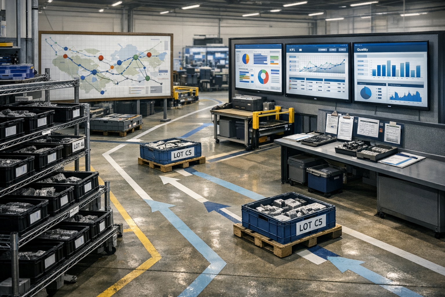
    Real-time production visibility is the ability to see current production status, performance, and issues as they happen (or with minimal delay) across lines, cells, or plants. It typically combines data from machines, operators, and business systems into a coherent operational view. The goal is not just dashboards, but faster detection of deviations, bottlenecks, and material or documentation problems. In most regulated plants, this visibility is selective and prioritized around critical products, assets, or process steps, rather than being a fully comprehensive, second-by-second digital twin.

    At a practical level, real-time often means seconds to a few minutes of latency, depending on network, system design, and validation constraints. Critical events such as equipment alarms or interlocks may be closer to true real time, while complex KPIs (OEE, yield, schedule adherence) are usually near real time or refreshed in short intervals. The value comes from timely, trustworthy information, not from zero latency. If the data is incomplete, poorly contextualized, or not validated, it will erode trust and can be worse than slower but reliable reports.

    What it includes in a typical regulated plant

    In a regulated manufacturing environment, real-time production visibility usually focuses on a few core areas. First is status visibility: which orders or lots are running on which assets, their step or operation, current state (running, changeover, down, waiting on QA, etc.), and estimated completion times. Second is performance visibility: throughput, scrap, rework, changeover progress, and basic OEE components like availability and performance, often aggregated per line or product family.

    Third is constraint and issue visibility: where queues are building, what is starved or blocked, which holds or nonconformances are impacting flow, and the current load on key shared resources (e.g., inspection, ovens, autoclaves, test stands). Fourth is compliance-critical context: links to the active work instructions, batch records, equipment status (e.g., calibration, maintenance due), and material genealogy so decisions do not detach from controlled information. The level of detail and latency varies heavily by site, dictated by system capabilities, integration coverage, and what has actually been validated for use in operations.

    How it is implemented on top of existing systems

    Real-time visibility is almost always an overlay on top of existing MES, SCADA, historians, LIMS, QMS, and ERP, not a wholesale replacement of those systems. Data is typically collected from machine controllers, sensors, shop-floor terminals, and transactional systems, then normalized and contextualized into a production model (lines, cells, routes, orders, lots, equipment). Integration often uses a mix of OPC, message buses, APIs, flat files, and manual data entry where automation is not yet feasible.

    In brownfield environments, different assets and processes have very different levels of connectivity and data quality. Newer equipment may provide structured, timestamped data, while legacy machines and manual workstations may rely on operators entering codes at terminals or scanning barcodes. Real-time visibility tools must therefore cope with partial automation, missing values, conflicting timestamps, and divergent master data. The result is a blended picture: some production areas are highly instrumented and near real time; others are updated only when an operation is completed or a batch record is signed.

    Constraints, tradeoffs, and common failure modes

    Achieving real-time production visibility in regulated environments is constrained by validation requirements, data integrity expectations, and change control. Every integration, transformation rule, and KPI definition may need documented requirements, testing, and traceability, which slows down iteration and can limit how dynamic the system can be. Plants often end up choosing between a smaller, validated scope of highly reliable data, and a broader, faster, but less trusted view. When this choice is not made explicitly, the program tends to stall or produce dashboards that no one relies on for critical decisions.

    Common failure modes include dashboards built without robust master data, causing incorrect order-to-asset mappings and misleading WIP status. Another frequent issue is mixing unvalidated real-time data with information used in regulated records, without clear separation or disclaimers, which creates compliance and audit risk. Latency is also often underestimated: queries against ERP or MES that are not designed for real-time load can degrade system performance or trigger unplanned downtime. Finally, ownership gaps—no one responsible for data definitions, quality, and lifecycle—lead to drift between what the screens show and what the systems of record state.

    Why it rarely means one unified, fully real-time replacement system

    In aerospace-grade and similarly regulated environments, attempting to achieve real-time visibility by replacing core systems (MES, ERP, QMS) with a single new platform usually fails or under-delivers. The qualification and validation burden for such a replacement is large, because these systems touch batch records, genealogy, release decisions, and configuration-controlled data. Downtime required for migration, cutover, and stabilization is often incompatible with production commitments and contractual obligations. The risk of disrupting established audit trails and traceability chains makes leadership understandably cautious.

    Furthermore, the plant-wide integration complexity—multiple vendors, custom interfaces, homegrown tools—makes full replacement a multi-year, multi-site program that often exceeds initial budget and appetite for change. Most organizations therefore adopt a coexistence model: a real-time visibility or manufacturing intelligence layer on top of validated transactional systems, with carefully governed interfaces and clear scope boundaries. This approach still requires rigorous change control and testing, but isolates risk and lets sites steadily improve visibility without jeopardizing core records of truth.

    How to scope and sustain real-time visibility realistically

    A realistic approach is to define specific, high-value use cases first (for example, shift-level OEE for bottleneck lines, or live queue status before critical inspection steps) and build visibility around those. This narrows the integration and validation scope, making it more achievable while still delivering meaningful benefit. From there, sites can expand coverage iteratively, extending to adjacent equipment, adding KPIs, and improving data quality as they go. Each expansion should be treated as a controlled change, with updated documentation, tests, and stakeholder training.

    Sustaining real-time production visibility requires clear ownership of data models, KPI definitions, and interface behavior, not just ownership of the visualization tool. It also requires operational discipline: operators need clear expectations about timely data entry where automation is not present, and engineering/IT teams need processes to handle failures gracefully when upstream systems or networks are degraded. Ultimately, real-time visibility becomes useful when leaders and supervisors trust it enough to act on it, understand its limitations by area, and know which parts of the picture are authoritative versus purely informational.

  • Ramp-up

    Ramp-up is the controlled increase of production volume, staffing, equipment use, or system activity from an initial level toward a planned operating rate. In manufacturing, it commonly refers to the period after a product launch, line start, process change, or capacity addition when output is increased while performance is monitored.

    During ramp-up, teams typically track whether materials, work instructions, labor, equipment, quality checks, and system transactions can support the higher rate. In MES, ERP, and planning contexts, ramp-up may affect routings, work orders, schedules, inventory demand, inspection load, and throughput assumptions.

    Ramp-up is not the same as startup, which usually refers to the initial act of bringing a process, line, or system into operation. It is also different from capacity, which describes the amount of output a process can support under defined conditions. Ramp-up is the transition toward that expected operating level.

  • What roles should participate in RCA for critical safety-of-flight nonconformances?

    For critical safety-of-flight nonconformances, root cause analysis should be cross-functional from the start. Quality typically facilitates, but quality alone is not enough. At minimum, you usually need the people who understand the requirement, the process that produced the condition, the evidence trail, and the authority to contain risk and approve corrective action.

    Core participants

    In most regulated aerospace and similar environments, the core RCA team should include these roles:

    In practice, this connects to data integrity, version control and audit when teams need to turn the answer into repeatable execution habits.

    • Quality engineering or quality management: owns the NCR workflow, evidence discipline, containment tracking, and linkage to CAPA or equivalent corrective action processes.
    • Responsible design or product engineering: confirms the requirement, characteristic criticality, functional impact, and whether the issue is design interpretation, tolerance stack-up, process capability, or execution failure.
    • Manufacturing or process engineering: analyzes routing, work instructions, tooling, fixtures, machine parameters, process controls, and recent changes.
    • Production supervision and the operator or inspector closest to the event: provides factual sequence-of-events detail that is often missing from formal records. Excluding frontline knowledge is a common RCA failure mode.
    • MRB authority or equivalent disposition authority: separates immediate disposition decisions from long-term corrective action and keeps the investigation grounded in product risk.
    • Program or business leadership for major events: ensures resourcing, customer communication paths, schedule impact management, and escalation discipline where the issue affects delivered or deliverable hardware.

    Roles that are often required depending on the case

    Critical safety-of-flight events usually pull in additional functions. Whether they are mandatory depends on your product, customer contract, internal procedures, and where the failure originated.

    • Supplier quality and supplier engineering if the nonconformance originated in purchased material, special processing, calibration services, or outside processing. If the supplier owns part of the cause chain, they need to participate directly, not just receive a corrective action request.
    • Special process engineering for heat treat, coating, bonding, welding, NDT, plating, composites, sterilization, or other tightly controlled processes where certification and parameter history matter.
    • Metrology, test, or labs when measurement method, fixture bias, software revision, environmental conditions, or test setup may have contributed. Many RCAs go wrong because they assume the detection method is valid without checking MSA, calibration status, or setup repeatability.
    • Configuration management or document control if there is any chance the event is tied to drawing revision mismatch, obsolete work instructions, uncontrolled local copies, or incorrect model-based definition release.
    • Maintenance, controls, or equipment engineering if machine condition, preventive maintenance gaps, alarms, overrides, sensor drift, or PLC or HMI changes may be involved.
    • PLM, MES, ERP, or QMS system owners when the event may involve bad master data, routing mismatch, serialization gaps, missing as-built records, or interface failures between systems. In brownfield plants, these are common contributors and often missed.
    • Training or competency owners when qualification, certification, or recency of training is in question.
    • Materials, planning, or receiving quality where lot mix, substitution, shelf-life, handling, storage, or traceability breaks may be causal.

    Who should lead?

    Usually, quality leads the investigation process, but the technical lead should match the dominant cause path. If the likely cause is process control, manufacturing engineering may drive the technical analysis. If the likely cause is requirement interpretation or design intent, engineering may need to lead that portion. What matters is that one role owns coordination and evidence control, while technical ownership sits with the people competent to test the actual failure theory.

    That distinction matters. A lot of weak RCAs are really documentation exercises run by whoever owns the form.

    Who should not be left out

    Three omissions are especially risky for safety-of-flight cases:

    • The person who knows the real shop-floor sequence. Formal travelers and system timestamps rarely capture workarounds, interruptions, re-clamping, tool swaps, or local decisions.
    • The requirement owner. Teams sometimes investigate process variation before confirming the requirement, characteristic classification, and functional effect.
    • The system or data owner when records conflict. If MES, ERP, PLM, QMS, calibration, and maintenance data do not agree, the RCA can be built on the wrong chronology.

    Boundaries and controls for critical cases

    For critical safety-of-flight nonconformances, the RCA team is only one part of the response. You also typically need explicit controls around containment, segregation, traceability review, shipped product impact assessment, and change control for any corrective action. If the proposed fix touches validated workflows, qualified equipment, approved process parameters, or controlled documentation, implementation will usually require formal review and may take longer than the urgency of the event would suggest.

    That is normal in regulated environments. Fast action without controlled evidence and change discipline often creates a second problem.

    Practical rule

    If a role can answer one of these questions, it probably belongs in the RCA:

    • What requirement was actually violated?
    • How could the process physically create this condition?
    • Can the detection method itself be trusted?
    • What else, by serial, lot, process window, or supplier batch, may be affected?
    • What system, document, or equipment changes happened near the event?
    • Who has authority to contain risk and approve the corrective path?

    For most critical safety-of-flight events, that means a small core team plus targeted subject-matter experts, not a giant meeting. Too few roles misses causes. Too many turns RCA into a status review.

  • What is MES and MOM?

    MES and MOM are closely related concepts, but they are not interchangeable. In most industrial and regulated environments, MES is treated as a specific system layer, while MOM refers to a broader set of operations management capabilities that may span several systems.

    What is MES?

    A Manufacturing Execution System (MES) is the layer between ERP and the shop floor that manages and records the execution of production in near real time. In practice, an MES typically covers some or all of the following functions:

    In practice, this connects to shop floor execution control when teams need to turn the answer into repeatable execution habits.

    • Order dispatching and sequencing from ERP or planning systems to specific lines, cells, or machines
    • Electronic routing and enforcement of process steps (e.g., operations, resources, tools)
    • Electronic batch records or device history records, including operator sign-offs in regulated industries
    • Data collection from machines, test equipment, and operators (parameters, measurements, events)
    • In-process quality checks, holds, and nonconformance logging
    • Material tracking, work-in-process (WIP) visibility, and basic genealogy
    • OEE and basic performance metrics based on actual production events

    MES is usually a specific, named application (or closely integrated set of applications) that must be validated, integrated with existing systems, and maintained under change control. It is commonly positioned as the “system of record” for what actually happened during production.

    What is MOM?

    Manufacturing Operations Management (MOM) is a broader management discipline and capability set. It includes MES-like execution functions but also spans planning, quality, maintenance, and performance management at the operations level.

    Depending on the vendor and plant, MOM may encompass:

    • Production operations management (execution, dispatching, WIP, genealogy)
    • Quality operations management (in-process checks, SPC, deviation/CAPA integration, release workflows)
    • Maintenance operations management (basic asset status, coordination with CMMS, downtime categorization)
    • Inventory and material operations (material movements, consumption, kitting, limited warehouse functions)
    • Performance and analytics (KPIs, OEE, losses, bottleneck analysis, shift/plant dashboards)

    Some vendors brand their entire operations suite as a MOM platform, of which MES is one module. Others use “MOM” more as an architectural or process reference model (for example, based on ISA-95), even when the actual systems are a mix of MES, LIMS, QMS, CMMS, and custom tools.

    How do MES and MOM relate in real plants?

    In brownfield, regulated environments, the relationship between MES and MOM is often shaped by existing systems and constraints rather than by clean reference models:

    • MES as a subset of MOM: Many organizations treat MES as the execution subset of a broader MOM strategy. MOM capabilities may be spread across MES, QMS, LIMS, CMMS, data historians, and reporting tools.
    • Overlapping functions: Quality and maintenance functions in MES often overlap with standalone QMS and CMMS. Which system is the “source of truth” for a given function (e.g., nonconformance, calibration) must be defined explicitly.
    • Multiple MES-like systems: Plants may run several MES-like applications (line control systems, LIMS, custom shop-floor IT) that together form the effective “MOM” landscape, even if none is labeled as such.
    • ERP vs. MOM boundaries: In some implementations, ERP holds more detailed production and inventory logic, leaving MES relatively thin. In others, MES/MOM absorb more logic to keep ERP simpler. The split is rarely identical across sites.

    Why does the distinction matter in regulated, long-lifecycle environments?

    The MES vs. MOM distinction matters less as terminology and more as a way to think about responsibility, integration, and validation:

    • Scope and expectations: Labeling a project as “MES” tends to focus scope on execution and electronic records. Labeling it as “MOM” often implies broader changes to quality workflows, maintenance coordination, and performance reporting.
    • Validation and change control: In regulated contexts, MES changes can directly affect product records, electronic signatures, and traceability. Expanding MES into a full MOM platform increases validation scope and change-control overhead.
    • System coexistence: A MOM vision usually has to coexist with existing MES, QMS, PLM, LIMS, and historians. Full replacement strategies frequently stall due to qualification burden, downtime risk, and integration debt. Incremental integration and clear system-of-record choices are usually safer.
    • Traceability and genealogy: Deciding where genealogy, batch history, and device history records are mastered (MES vs. other MOM components) impacts auditability, data integrity controls, and cross-system reconciliation efforts.

    What should a practitioner focus on when hearing “MES” vs. “MOM”?

    When these terms come up in projects or vendor discussions, it is useful to clarify:

    • Which concrete functions are in scope (e.g., EBR/DHR, routing control, in-process quality, OEE, maintenance, material management)
    • Which systems are intended as system of record for each function, given existing ERP, QMS, LIMS, CMMS, PLM, and historians
    • How validation, change control, and audit trails will be managed across these systems
    • What the migration or coexistence path looks like, recognizing that wholesale replacement of legacy MES or QMS is often infeasible in one step

    In summary, MES is typically the execution-focused system layer on the shop floor, while MOM is a broader operations management scope that may involve multiple systems. The exact boundary between them depends heavily on plant history, vendor choices, and regulatory constraints, so definitions should always be tied back to specific functions, data ownership, and system responsibilities.

  • What is the ISA-95 hierarchy of plants?

    ISA-95 does not define a hierarchy of plants as a corporate org chart. Instead, it provides two related but distinct structures:

    • a functional hierarchy of control and information levels (Levels 0 to 4), and
    • a physical & organizational breakdown of manufacturing locations and equipment (enterprise, site, area, etc.).

    1. ISA-95 functional levels (0 to 4)

    These levels describe what types of functions and systems operate where, not who reports to whom:

    In practice, this connects to a connected execution platform when teams need to turn the answer into repeatable execution habits.

    1. Level 0 – Process
      Physical production process and material transformation (machines, utilities, operators interacting with equipment).
    2. Level 1 – Basic Control
      Real-time control of equipment and processes (PLCs, DCS, motion control, basic interlocks).
    3. Level 2 – Monitoring & Supervisory Control
      Supervisory control and visualization (SCADA, HMIs, historian data collection, alarm management).
    4. Level 3 – Manufacturing Operations Management
      Execution and coordination of production at the plant / site level (MES, LIMS, WMS, detailed scheduling, batch management, electronic records).
    5. Level 4 – Business Planning & Logistics
      Enterprise-level planning and logistics (ERP, APS, supply chain planning, order management, financials).

    This stack is often drawn as a hierarchy, but it is really a functional separation of concerns and interfaces between real-time control and enterprise systems.

    2. ISA-95 physical and organizational model (plant-related hierarchy)

    Within this functional context, ISA-95 defines a physical & organizational breakdown of production. The most plant-relevant part is:

    • Enterprise: The overall company or corporation.
    • Site: A geographically distinct location (often what people informally call a “plant” or “factory”). One enterprise usually has multiple sites.
    • Area: A logical or physical subdivision within a site (e.g., machining hall, assembly area, mixing area, cleanroom block).
    • Production line / process cell: A coordinated set of equipment used to produce a specific product or product family.
      • Production line is more typical in discrete/assembly manufacturing.
      • Process cell is more typical in batch/continuous processes.
    • Unit: A major processing or production unit operation (e.g., reactor, filler, paint booth, CNC cell, test cell).
    • Equipment module: A functional grouping of equipment within a unit that executes specific operations (e.g., dosing skid, robot + vision cell, clamp and torque station).
    • Control module: The smallest control-level elements (e.g., a valve, pump, actuator, drive, sensor group) that can be commanded individually.

    This structure is used to model where manufacturing happens and how equipment is organized, not to dictate reporting lines or business ownership. A large regulated company may call each site a “plant” and group several sites under one enterprise.

    3. How this relates to “hierarchy of plants” in practice

    In many organizations, people use “plant hierarchy” loosely to mean a mix of:

    • Enterprise > Region > Site > Area > Line / Cell
    • ERP organizational structure (company code, plant, storage location)
    • CMMS asset hierarchy
    • MES equipment and location model

    ISA-95 can provide a common reference, but it does not prescribe a corporate hierarchy of plants. Instead, it provides consistent levels and object types so that ERP, MES, QMS, PLM, and automation systems can map to a shared model.

    4. Brownfield and regulated environment considerations

    In regulated, long-lifecycle environments, the ISA-95 model usually has to be layered on top of existing structures rather than imposed from scratch:

    • Legacy definitions of “plant” and “site” in ERP and regulatory filings may not match ISA-95 terms exactly. Changing them can affect validated processes, product registrations, and audit trails.
    • MES and SCADA often already have their own equipment models. Aligning them to the ISA-95 structure typically requires careful mapping, not wholesale replacement.
    • Validation and change control limit how aggressively you can restructure the hierarchy. Even a “naming alignment” may be a controlled change in GxP or aerospace environments.
    • Integration debt (custom interfaces, point-to-point data flows) may rely on existing plant codes, line IDs, and area names, which complicates cleanup or standardization.

    Because of these realities, full replacement of your existing plant and equipment hierarchies with a “pure” ISA-95 model often fails or stalls, largely due to:

    • qualification and validation burden for reconfigured MES/ERP structures,
    • downtime required to migrate and verify data and interfaces,
    • complexity of reconciling multiple legacy hierarchies across sites and vendors, and
    • traceability risks if historical records must be re-keyed or remapped.

    A more practical strategy is typically to map existing plant/site/area/line concepts to ISA-95 objects and use those mappings in integration and master data management, rather than attempting a single big-bang hierarchy replacement.

    5. Key takeaways

    • ISA-95 defines functional levels (0–4) and a physical & organizational hierarchy (enterprise, site, area, line/cell, unit, equipment module, control module).
    • It does not define a corporate reporting hierarchy or guarantee that your “plant” concept matches a single ISA-95 level.
    • In brownfield, regulated environments, treat ISA-95 as a reference model for mapping rather than a mandate to redesign your entire plant hierarchy.
  • Who should own master data for AI use cases in aerospace manufacturing?

    No single team should own it alone.

    In aerospace manufacturing, master data for AI use cases usually needs a federated ownership model: business functions own the data definitions, rules, and approval authority for their domains, while IT and data teams own the technical controls, integration patterns, access, lineage, and stewardship workflow.

    In practice, this connects to ERP, MES, and PLM integration paths when teams need to turn the answer into repeatable execution habits.

    A practical split looks like this:

    • Engineering owns engineering master data such as part definitions, configurations, approved structures, and revision intent where PLM is the source of record.
    • Operations owns routings, work centers, standard work attributes, production context, and certain execution parameters where MES or ERP governs them.
    • Quality owns defect codes, inspection characteristics, disposition-related reference data, and quality status logic where QMS or MES holds the controlled values.
    • Supply chain or materials owns supplier, material, and sourcing-related master data where ERP or supplier systems are authoritative.
    • IT and data governance own identity, integration, synchronization rules, data quality monitoring, metadata management, retention controls, and stewardship processes across systems.

    For AI, the key point is that ownership should stay closest to the process authority, not be reassigned to the data science team just because the data is being used for models. AI teams are consumers and sometimes contributors to feature engineering, labeling logic, and feedback loops, but they should not become the uncontrolled owner of regulated operational master data.

    What matters more than the org chart

    The real requirement is not a single owner title. It is explicit accountability for:

    • system of record by data domain
    • approved definitions and code sets
    • revision and change control
    • traceability from source data to AI input and output
    • stewardship for exceptions, duplicates, and conflicts
    • validation of transformations and integration logic where required by internal quality procedures

    If those controls are weak, naming one executive owner will not fix the problem. AI performance will drift, model outputs will be hard to explain, and auditability will degrade.

    Why this is harder in aerospace plants

    In brownfield aerospace environments, master data is rarely cleanly centralized. The same part, operation, or quality code may exist across PLM, ERP, MES, QMS, data historians, spreadsheets, and supplier portals with different timing, granularity, or revision behavior. That means ownership is partly organizational and partly architectural.

    Full replacement of legacy systems is often not realistic. It commonly fails because of qualification burden, validation cost, downtime risk, integration complexity, and the long lifecycle of production assets and programs. In practice, most plants need governed coexistence: clear source systems, mapped relationships, controlled replication, and documented override rules.

    That is especially important for AI use cases such as predictive quality, scheduling support, anomaly detection, and knowledge retrieval. If the underlying master data is inconsistently synchronized, the model may appear accurate in a pilot but fail when exposed to live revisions, supplier changes, or shop-floor exceptions.

    Recommended operating model

    For most aerospace manufacturers, the most durable model is:

    • Executive accountability through a cross-functional data governance council
    • Domain ownership by the business function that is accountable for process correctness
    • Technical stewardship by IT or a central data team
    • AI-specific controls for feature definitions, training data lineage, model versioning, and retraining triggers

    If you want one named owner for coordination, make it a data governance lead or chief data role with authority to enforce standards across functions. But that role should coordinate ownership, not replace the domain owners who control the actual business meaning of the data.

    Common failure modes

    • IT is named owner of all master data but cannot approve process meaning or code changes.
    • Engineering assumes PLM is authoritative for everything, even when execution and quality data are maintained elsewhere.
    • A data science team creates derived reference values that quietly become operational standards without change control.
    • Plants run local spreadsheets or tribal conventions that never reconcile back to enterprise systems.
    • AI teams train on historical data snapshots without accounting for revision history, superseded attributes, or missing genealogy.

    If those conditions exist, ownership is not actually defined, even if a governance slide says it is.

    Bottom line

    Master data for AI in aerospace manufacturing should be jointly governed, with domain ownership in the business, technical stewardship in IT, and explicit controls for traceability, change management, and source-of-record integrity. If your organization is looking for one department to own everything, the answer is usually no.

  • Where should we start with MES if our main goal is reducing aerospace scrap and rework?

    Start from the highest-cost, most diagnosable scrap and rework

    When the primary goal is reducing aerospace scrap and rework, the best starting point for MES is not the entire plant or the easiest area to digitize, but the operations where quality losses are both expensive and diagnosable. In practice, this often means complex assemblies, special processes, and test/inspection steps that gate release. Start by mapping where scrap and rework actually occur by operation, part family, and defect type, using existing QMS and ERP data even if it is incomplete. Then select 1–3 operations where defects are frequent, cost per defect is high, and the process is at least somewhat stable. This focus keeps validation and integration scope manageable while still creating measurable impact.

    A common failure mode is starting MES in a “low-risk pilot” area with little historical scrap, simply because it is simpler to automate. This may succeed technically but show negligible business impact, making it harder to justify the next phases. Another failure mode is trying to digitize an area with highly variable work content and weak process discipline, where MES primarily exposes noise rather than root causes. By anchoring on defect and rework data instead of perceived convenience, you are more likely to deploy capabilities that actually reduce nonconformance.

    In practice, this connects to shop floor execution control when teams need to turn the answer into repeatable execution habits.

    Prioritize a consistent digital traveler and enforced work instructions

    For scrap and rework reduction, the foundational MES capability is a robust digital traveler with enforced work instructions, not advanced analytics or automated scheduling. The traveler should drive the correct sequence of operations, required signoffs, and key verifications for each configuration. Start by converting paper travelers and work instructions for your chosen high-defect area into a controlled digital form with version control and clear applicability rules. Ensure the system can block progression when mandatory steps, checks, or approvals are incomplete.

    A frequent failure mode is underestimating how much effort is needed to clean up and standardize work instructions before digitization. In aerospace environments, travelers often have handwritten notes, tribal workarounds, and local variants that are not formally captured. Pushing this complexity straight into MES creates exceptions, workarounds, and audit risk. It is usually necessary to simplify and rationalize the instructions, even if this delays deployment. Without enforced, unambiguous digital instructions, MES becomes an expensive electronic file cabinet, and scrap drivers tied to missed or misinterpreted steps will persist.

    Make defect and rework data capture structured and mandatory

    MES cannot reduce scrap and rework if it only reflects pass/fail outcomes; it has to capture rich, structured defect and rework data at the point of occurrence. A practical starting scope is to standardize defect codes, locations, and suspected causes for the targeted area, and then configure MES to make those fields mandatory whenever a nonconformance or rework is recorded. This does not replace your QMS, but it can feed better, more granular data into it. Over time, this enables more effective root cause analysis across parts, shifts, operators, equipment, and suppliers.

    Typical failure modes include allowing free-text defect descriptions without structure, which prevents meaningful analysis, or making defect capture so cumbersome that operators bypass the system or log generic codes. Another pitfall is creating an overly complex defect taxonomy up front, which becomes unmanageable in a high-mix aerospace environment. A balanced approach is to start with a concise but meaningful code set that maps to your existing QMS categories, and refine it based on actual usage and problem-solving needs under change control.

    Integrate only the minimum systems needed to see and act on quality issues

    Scrap and rework reduction often tempts teams into broad integration efforts (ERP, PLM, QMS, test systems, tooling, and more). For a starting MES scope, this is rarely necessary and often harmful. Focus first on the minimal integrations required to ensure that operators have the correct configuration and that quality data can be traced: typically part and order data from ERP and, where needed, configuration and revision data from PLM. Additional integrations, such as automated test results or gauge data, can be phased in once basic workflows are stable and validated.

    Over-integration too early creates validation burden, new failure modes, and unplanned downtime when upstream systems change. In aerospace-grade environments, each integration touchpoint must be controlled, tested, and documented; rushed efforts can add more risk than benefit. A practical guideline is to ask: will this integration directly improve our ability to prevent, detect, or analyze defects in the chosen scope in the next 6–12 months? If not, defer it. Build observability around MES interfaces so you can quickly detect and triage failures that might impact quality records.

    Avoid full rip-and-replace; coexist with QMS, ERP, and legacy systems

    If your primary goal is to cut scrap and rework, a full replacement of existing MES, QMS, or shop-floor tools is almost never the right starting point in aerospace. Qualification and validation burdens, long equipment lifecycles, and multi-system traceability make large-scale cutovers slow, risky, and expensive. Instead, treat the new or expanded MES as one more controlled component in a larger quality and manufacturing stack. Use it to strengthen specific weak links—like traveler control, defect data capture, or operator guidance—while keeping validated legacy systems running.

    Full rip-and-replace efforts typically fail or stall because they require extended downtime windows that are not available, simultaneous retraining of the entire workforce, and complete re-validation of integrated processes and data flows. They also tend to underestimate integration complexity with specialized aerospace tooling and test stands that have been in service for decades. A phased coexistence approach, with clear interfaces and data ownership, allows you to realize quality improvements while maintaining compliance and production continuity.

    Define a narrow, measurable initial outcome and how you will test it

    Before starting, define a specific, narrow objective tied to scrap and rework that your initial MES scope is expected to influence, such as reducing a particular defect category by a defined percentage on a defined product family. Align this objective with how you will measure and attribute changes—using existing scrap reports, QMS data, and where needed, additional MES reports. The objective should be focused enough that you can see a signal within 6–18 months, acknowledging aerospace cycle times and qualification constraints. This framing helps prevent scope creep and ensures design decisions favor data and controls that directly support the chosen metric.

    A common failure mode is implementing MES with broad, vague goals like “improve quality” or “go paperless,” which are difficult to tie to concrete scrap and rework reductions. Another is not planning for how changes will be validated and introduced under change control, especially when process steps, instructions, or data capture requirements change. Build a simple but explicit plan for user acceptance testing, validation evidence, and rollout sequencing, including how you will handle discovered defects in the MES configurations themselves. This discipline is critical in regulated environments where process documentation and quality records are part of the product’s evidence trail.

    Connecting this to your situation: where to start in practice

    In a typical aerospace plant with a mix of legacy MES, manual travelers, and a separate QMS, a pragmatic starting point is a single product family and a limited set of operations with recurring nonconformances. Begin by stabilizing and digitizing the traveler and work instructions there, then enforce structured defect and rework capture at those same operations. Integrate only enough to ensure correct configuration control and basic traceability, and keep QMS as the system of record for formal nonconformances and corrective actions. Use the improved data to run more targeted root cause analysis and drive specific process changes, tracked under your existing change control machinery.

    As you accumulate evidence that this localized MES capability is helping reduce scrap and rework—and understand its limitations—you can expand to adjacent operations, additional product families, or richer integrations (e.g., automated test results). At each step, reassess whether the next MES feature or integration actually improves your ability to prevent or analyze defects. By treating MES expansion as a series of small, validated steps rather than a one-time digital transformation, you are more likely to achieve durable quality gains without compromising compliance or production stability.